EP1125845B1 - Widerlager zum Andrücken von Verpackungsmaterial an ein Klebstoffauftragungssystem und Klebstoffauftragungssystem - Google Patents
Widerlager zum Andrücken von Verpackungsmaterial an ein Klebstoffauftragungssystem und Klebstoffauftragungssystem Download PDFInfo
- Publication number
- EP1125845B1 EP1125845B1 EP01100561A EP01100561A EP1125845B1 EP 1125845 B1 EP1125845 B1 EP 1125845B1 EP 01100561 A EP01100561 A EP 01100561A EP 01100561 A EP01100561 A EP 01100561A EP 1125845 B1 EP1125845 B1 EP 1125845B1
- Authority
- EP
- European Patent Office
- Prior art keywords
- adhesive
- application system
- packaging material
- counter
- support
- Prior art date
- Legal status (The legal status is an assumption and is not a legal conclusion. Google has not performed a legal analysis and makes no representation as to the accuracy of the status listed.)
- Expired - Lifetime
Links
- 239000000853 adhesive Substances 0.000 title claims abstract description 34
- 230000001070 adhesive effect Effects 0.000 title claims abstract description 34
- 239000005022 packaging material Substances 0.000 title claims description 32
- 238000003825 pressing Methods 0.000 title claims description 5
- 235000019504 cigarettes Nutrition 0.000 claims abstract description 15
- 239000000463 material Substances 0.000 claims description 18
- 239000000123 paper Substances 0.000 abstract description 6
- 239000012943 hotmelt Substances 0.000 abstract 1
- 239000003292 glue Substances 0.000 description 19
- 238000004026 adhesive bonding Methods 0.000 description 10
- 238000004806 packaging method and process Methods 0.000 description 5
- 238000012423 maintenance Methods 0.000 description 3
- 239000004831 Hot glue Substances 0.000 description 2
- 238000004140 cleaning Methods 0.000 description 2
- 230000007246 mechanism Effects 0.000 description 2
- 238000012856 packing Methods 0.000 description 2
- 238000011109 contamination Methods 0.000 description 1
- 238000005520 cutting process Methods 0.000 description 1
- 238000006073 displacement reaction Methods 0.000 description 1
- 238000004519 manufacturing process Methods 0.000 description 1
- 239000000758 substrate Substances 0.000 description 1
- 238000011144 upstream manufacturing Methods 0.000 description 1
Images

Classifications
-
- B—PERFORMING OPERATIONS; TRANSPORTING
- B65—CONVEYING; PACKING; STORING; HANDLING THIN OR FILAMENTARY MATERIAL
- B65B—MACHINES, APPARATUS OR DEVICES FOR, OR METHODS OF, PACKAGING ARTICLES OR MATERIALS; UNPACKING
- B65B51/00—Devices for, or methods of, sealing or securing package folds or closures; Devices for gathering or twisting wrappers, or necks of bags
- B65B51/02—Applying adhesives or sealing liquids
- B65B51/023—Applying adhesives or sealing liquids using applicator nozzles
Definitions
- the invention relates to an abutment for pressing packaging material, especially of material webs, blanks, Folding flaps of packs or other parts of packs of cigarette packs, to an adhesive application system and an adhesive application system for applying adhesive to packaging material.
- Glue is increasingly being applied in modern packaging machines Nozzle application systems for use. Basically here distinguish between contact nozzles and contactless nozzle systems.
- a known contact nozzle system from VALCO a fixedly positioned nozzle from the folding box blank to be glued or blank of a cigarette box overflowed.
- leaf springs which are essentially in the form of sheets have the disadvantage, however, that these, although originally well positioned for maintenance or cleaning work adjusted, bent or the brackets insufficient be positioned.
- the consequences of this are soiling of glue on the nozzle, on the packaging and subsequent machines share as well a relatively poor gluing of the blanks.
- the invention is based on the object repeatable and realizable without much adjustment effort Ensure that the material to be glued is in contact with the nozzle head, with tolerance-related misalignments of the application nozzle to the material level in as many directions as possible and preferred can be compensated in all directions.
- an abutment for pressing Packaging material in particular material webs, blanks, Folding flaps of packs or other parts of packs from Cigarette packs, to an adhesive application system, wherein the abutment includes a resiliently mounted pressure element and the packaging material in a running direction between the pressure element and the adhesive application system movable is, which is further developed in that the pressure element when going through the packaging material in at least two translatory degrees of freedom is movable.
- the direction of travel of the packaging material lies in the X-axis direction and the pressure element in the Y-axis direction or opposite the Y-axis direction presses against the adhesive application system with also a Z axis that is perpendicular to that through the X and Y axes tense plane means the possibility of movement in one degree of freedom in particular a movement in one Axis direction or opposite to it.
- the movement in two Degrees of freedom means in particular a rotary movement by one of the axes, in particular a movement in one plane, the by two axes is spanned.
- a movement in two degrees of freedom means in particular the possibility of movement in two Axis directions or opposite to it or a movement in one axial direction coupled with a rotary movement around another Axis.
- Movement in three degrees of freedom means in particular a movement in any direction in three dimensions Room.
- adhesive means in particular also glue, in particular both cold glue and also hot glue.
- the abutment according to the invention Due to the abutment according to the invention, it is tilted of the adhesive application system relative to the material web level possible to compensate for this tilting and the thing to be glued Packing material flat on the nozzle head or the adhesive application system to press. This is particularly repeatable and possible without adjustment.
- tolerance-related misalignments of the adhesive application system or the corresponding application nozzle to the material level of the packaging material compensated.
- the restoring force is preferably of the resiliently mounted type Pressure element adjustable.
- the pressure element can preferably be moved in three degrees of freedom, which in particular causes misalignments due to tolerance the adhesive application system or an application nozzle to the material level can be compensated in all directions.
- three degrees of freedom means in particular that all in a Cartesian coordinate system or in three dimensions Space possible movements are possible. This is the pressure element especially movable in every conceivable way, both essentially in a linear motion and also in a rotary motion.
- At least one axis of rotation is preferably provided, can particularly easy to twist the adhesive application system be compensated. Also preferred are two or three Axes of rotation provided.
- the at least one axis of rotation is linear in one Guidance, especially across the direction of the packaging material, Height differences can also be moved be balanced. Pins are preferably used for this, which can be moved in the guide, for example in the Y-axis direction are.
- the resiliently mounted pressure element is preferably through at least one spring resettable.
- Embodiment is a particularly simple reset or Pressure force realizable, which is particularly preferably adjustable is. If preferably the pressure element at least is partially resilient, is one with few components Abutment to be manufactured can be realized.
- the pressure element preferably has a contact surface, with which the pressure element with the packaging material in Contact occurs, the contact surface at least at one abutment surface is arched, the supply of to be glued Packaging material also with certain local tolerances possible. Furthermore, in the configuration in which an essential Part of the contact surface is curved, namely in particular the part that is near and opposite the glue application system is arranged and can be brought into contact with the mobility of the Pressure element are reduced, while still the objective Object of the invention is solved and also the durability of the pressure element with their movable components increased becomes.
- the abutment area is the area in which the funded Packaging material can come into contact with the pressure element.
- the pressure element is preferably designed as a tilt.
- a flat surface in question that may and may be preferred is also arched in the bump area.
- the butt is preferably stored resiliently with an adjustable restoring force.
- the pressure element is preferably spherical in the abutment stored.
- the invention is further enhanced by an adhesive application system for applying adhesive to packaging material, in particular of material webs, blanks, folding flaps of packs or other pack parts of cigarette packs, one Abutment is provided so that the packaging material from the adhesive application system can be pressed against the abutment and wherein the packaging material in a running direction between a pressure element and the adhesive application system movable is solved, which is further developed in that the adhesive application system or part of it that is in contact with the Packaging material comes when going through the packaging material movable in at least one translational degree of freedom is.
- an adhesive application system for applying adhesive to packaging material, in particular of material webs, blanks, folding flaps of packs or other pack parts of cigarette packs, one Abutment is provided so that the packaging material from the adhesive application system can be pressed against the abutment and wherein the packaging material in a running direction between a pressure element and the adhesive application system movable is solved, which is further developed in that the adhesive application system or part of it that is in contact with the Packaging material comes when going through the
- This solution also solves the objective problem that namely a flat system of the material to be glued to the adhesive application system or at the nozzle head.
- tolerance-related misalignments of the application nozzle can occur or the adhesive application system to the material level in as many directions as possible and preferably in all directions be compensated.
- the adhesive application system or part of which movable in two or three degrees of freedom Preferably the part of the adhesive application system includes the nozzle head. If preferably the adhesive application system or part of which is stored in a resilient manner, in particular preferably with an adjustable restoring force, is a special one simple design of the adhesive application system possible.
- At least one axis of rotation is preferably provided with which Twists can be compensated particularly easily. If preferably the at least one axis of rotation linear in a guide, especially across the direction of the packaging material, is movable; can also easily make height differences be compensated for the pressure element.
- the adhesive application system or part of which resettable by at least one spring is at least partially resilient, a particularly simple design is possible.
- Preferably comprises a device for applying adhesive on packaging material, especially on parts of cigarette packs, an abovementioned abutment and / or an abovementioned one Adhesive applicator.
- a contact nozzle for example from VALCO, which has a nozzle body 11, a nozzle opening 12 and one Groove 10.
- nozzles are positioned, for example, in a fixed position and are from a folding box blank or a Blank when packing cigarettes in cigarette boxes overflowed or swept over. If, for example, blocks of cigarettes are already in the cigarette box and only the side tabs have to be glued and folded over, these are passed through appropriate nozzles, with the with side tabs to be glued Hot glue or cold glue can be glued. Appropriate gluing the nozzle has a groove 10 provided area over which the folding box blank moves becomes.
- the groove 10 in the nozzle surface or contact surface 14 is in Direction of movement of the blank opened and ends at a tear-off edge.
- glue passes over one Feed hole 13, which is shown in Fig. 2, via a nozzle opening 12 in the groove and comes with the movement of the blank transferred to this.
- the valve upstream of the supply bore ensures the supply and Switching off the glue flow and thus the positioning of the Glue trace depending on the movement of the blank.
- FIG. 2 shows the nozzle body 11 and paper 20 or thin cardboard, of which the blank consists, or the side tabs of the Blankets exist, on average. It is especially the flat one Contact between the nozzle body 11 and the paper 20 on the contact surface 14 shown.
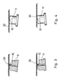
- nozzles When adjusting the nozzle, for example during maintenance or Cleaning work may result in insufficient positioning, which are shown schematically in Figs. 3 and 4.
- the nozzles are so to the blank or side tabs tilted that there is no longer a flat contact surface 14.
- the groove is from the paper or thin cardboard not closed on all sides, so that the glue also in different directions than the ones that are in the paper Connection with the contact surface in the direction of movement proper adjustment opening can escape. This leads to an unclean trace of glue and one bad Track break with the subsequent nozzle contamination and also Soiling of the subsequent parts of the apparatus with glue.
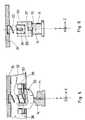
- FIG. 5 shows an embodiment of the present invention Invention in a schematic cross-sectional representation.
- the Nozzle body 10 is in contact with contact surface 14 here a pressure pad 33 shown.
- the pressure pad 33 will by a spring 32 in the direction of the nozzle body 11 or contact surface 14 pressed.
- In the Cartesian coordinates shown, namely the X, Y and Z axes press the spring 32 against the Y axis.
- a blank or the side tabs of a blank are moved between the pressure pad 33 and the nozzle body 11.
- the contact area of the pressure pad 33 is here spherical or arched. This configuration will an essentially perpendicular line contact to the direction of movement the material web generated.
- the pressure pad 33 is parallel to the paper movement attached pins in a guide or in elongated holes like this stored that both a displacement in the Y direction or opposite for this, as well as a rotation around the X axis can be compensated. In the latter case, the Pressure pad 33 about the axis of rotation 36, which is the center line of the Pins 35 corresponds to rotated.
- the abutment 30 further includes a holder 31, in which in particular the spring 32 is held is.
- a groove 37 is provided in the pressure block, to avoid contact with the glue-bearing area of the nozzle, if no blank or no side flaps of a blank passed between the nozzle and the pressure pad become.
- a flat surface may also be provided, preferably has a curved abutment surface. In this case it makes sense to design the pressure block in the manner of a tilt, at the restorative measures or means are provided that the Pressure pad 33 always presses in the direction of a starting position.
- nozzle alone or in combination with one described above Abutment designed to be movable.
Landscapes
- Engineering & Computer Science (AREA)
- Mechanical Engineering (AREA)
- Making Paper Articles (AREA)
- Wrapping Of Specific Fragile Articles (AREA)
- Coating Apparatus (AREA)
- Adhesives Or Adhesive Processes (AREA)
Description
- Fig. 1
- ein Düsenkopf schematisch von unten dargestellt,
- Fig. 2
- eine schematische Schnittdarstellung des Düsenkopfes von Fig. 1 in Seitenansicht mit einem Teil eines zu beleimenden Faltschachtelzuschnitts,
- Fig. 3
- eine der Fig. 2 entsprechende Schnittdarstellung, wobei der Düsenkopf in zwei verschiedenen Richtungen gegenüber dem Faltschachtelzuschnitt, verkippt ist,
- Fig. 4
- eine Seitenansicht der Düse, bei der zwei verschiedene Verkippungen dargestellt sind,
- Fig. 5
- eine schematische Querschnittsdarstellung einer Düse mit einem Widerlager, und
- Fig. 6
- eine schematische Schnittdarstellung der Elemente der Fig. 5 aus einer anderen Richtung.
Claims (17)
- Widerlager (30) zum Andrücken von Verpackungsmaterial (20), insbesondere von Materialbahnen, Zuschnitten, Faltlappen von Packungen oder anderen Packungsteilen von Zigarettenpackungen, an ein Klebstoffauftragungssystem (11), wobei das Widerlager (30) ein rückstellend gelagertes Andruckelement (33) umfasst und das Verpackungsmaterial (20) in einer Laufrichtung zwischen dem Andruckelement (33) und dem Klebstoffauftragungssystem (11) bewegbar ist, dadurch gekennzeichnet, dass das Andruckelement (33) beim Durchlaufen des Verpackungsmaterials (20) in wenigstens zwei translatorischen Freiheitsgraden bewegbar ist.
- Widerlager (30) nach Anspruch 1, dadurch gekennzeichnet, dass das Andruckelement (33) in drei Freiheitsgraden bewegbar ist.
- Widerlager (30) nach Anspruch 1 oder 2, dadurch gekennzeichnet, dass wenigstens eine Drehachse (36) vorgesehen ist.
- Widerlager (30) nach Anspruch 3, dadurch gekennzeichnet, dass die wenigstens eine Drehachse (36) linear in einer Führung (34), insbesondere quer zur Laufrichtung des Verpackungsmaterials, bewegbar ist.
- Widerlager (30) nach einem oder mehreren der Ansprüche 1 bis 4, dadurch gekennzeichnet, dass das rückstellend gelagerte Andruckelement (33) durch wenigstens eine Feder (32) rückstellbar ist.
- Widerlager (30) nach einem oder mehreren der Ansprüche 1 bis 4, dadurch gekennzeichnet, dass das Andruckelement (33) wenigstens teilweise federnd ausgestaltet ist.
- Widerlager (30) nach einem oder mehreren der Ansprüche 1 bis 6, dadurch gekennzeichnet, dass das Andruckelement (33) eine Kontaktfläche (14) aufweist, mit der das Andruckelement (33) mit dem Verpackungsmaterial (20) in Kontakt tritt, wobei die Kontaktfläche (14) wenigstens an einer Anstoßfläche gewölbt ausgebildet ist.
- Widerlager (30) nach einem oder mehreren der Ansprüche 1 bis 6, dadurch gekennzeichnet, dass das Andruckelement (33) als eine Kippe ausgestaltet ist.
- Widerlager (30) nach einem oder mehreren der Ansprüche 1 bis 8, dadurch gekennzeichnet, dass das Andruckelement (33) sphärisch im Widerlager (30) gelagert ist.
- Klebstoffauftragungssystem (11) zum Auftragen von Klebstoff auf Verpackungsmaterial (20), insbesondere von Materialbahnen, Zuschnitten, Faltlappen von Packungen oder anderen Packungsteilen von Zigarettenpackungen, wobei ein Widerlager (30) vorgesehen ist, so dass das Verpackungsmaterial (20) von dem Klebstoffauftragungssystem (11) an das Widerlager (30) drückbar ist und wobei das Verpackungsmaterial (20) in einer Laufrichtung zwischen einem Andruckelement (33) und dem Klebstoffauftragungssystem (11) bewegbar ist, dadurch gekennzeichnet, dass das Klebstoffauftragungssystem (11) oder ein Teil davon, das in Kontakt mit dem Verpackungsmaterial (20) kommt, beim Durchlaufen des Verpackungsmaterials (20) in wenigstens einem translatorischen Freiheitsgrad bewegbar ist.
- Klebstoffauftragungssystem (11) nach Anspruch 10, dadurch gekennzeichnet, dass das Klebstoffauftragungssystem (11) oder das Teil davon in zwei oder drei Freiheitsgraden bewegbar ist.
- Klebstoffauftragungssystem (11) nach Anspruch 10 oder 11, dadurch gekennzeichnet, dass dieses oder das Teil davon rückstellend gelagert ist.
- Klebstoffauftragungssystem (11) nach einem oder mehreren der Ansprüche 10 bis 12, dadurch gekennzeichnet, dass wenigstens eine Drehachse vorgesehen ist.
- Klebstoffauftragungssystem (11) nach Anspruch 13, dadurch gekennzeichnet, dass die wenigstens eine Drehachse linear in einer Führung, insbesondere quer zur Laufrichtung des Verpackungsmaterials (20), bewegbar ist.
- Klebstoffauftragungssystem (11) nach einem oder mehreren der Ansprüche 12 bis 14, dadurch gekennzeichnet, dass dieses oder das Teil davon durch wenigstens eine Feder rückstellbar ist.
- Klebstoffauftragungssystem (11) nach einem oder mehreren der Ansprüche 12 bis 14, dadurch gekennzeichnet, dass dieses oder das Teil davon wenigstens teilweise federnd ausgestaltet ist.
- Einrichtung zum Auftragen von Klebstoff auf Verpackungsmaterial (20), insbesondere auf Teilen von Zigarettenpackungen, mit einem Widerlager (30) nach einem oder mehreren der Ansprüche 1 bis 9 und/oder einem Klebstoffauftragungssystem (11) nach einem oder mehreren der Ansprüche 10 bis 16.
Applications Claiming Priority (2)
| Application Number | Priority Date | Filing Date | Title |
|---|---|---|---|
| DE10007220 | 2000-02-17 | ||
| DE10007220A DE10007220A1 (de) | 2000-02-17 | 2000-02-17 | Widerlager zum Andrücken von Verpackungsmaterial an ein Klebstoffauftragungssystem und Klebstoffauftragungssystem |
Publications (2)
| Publication Number | Publication Date |
|---|---|
| EP1125845A1 EP1125845A1 (de) | 2001-08-22 |
| EP1125845B1 true EP1125845B1 (de) | 2004-11-03 |
Family
ID=7631290
Family Applications (1)
| Application Number | Title | Priority Date | Filing Date |
|---|---|---|---|
| EP01100561A Expired - Lifetime EP1125845B1 (de) | 2000-02-17 | 2001-01-10 | Widerlager zum Andrücken von Verpackungsmaterial an ein Klebstoffauftragungssystem und Klebstoffauftragungssystem |
Country Status (7)
| Country | Link |
|---|---|
| US (1) | US6740161B2 (de) |
| EP (1) | EP1125845B1 (de) |
| JP (1) | JP2001277379A (de) |
| CN (1) | CN1309060A (de) |
| AT (1) | ATE281356T1 (de) |
| DE (2) | DE10007220A1 (de) |
| PL (1) | PL345877A1 (de) |
Families Citing this family (5)
| Publication number | Priority date | Publication date | Assignee | Title |
|---|---|---|---|---|
| EP1437303B2 (de) * | 2003-01-08 | 2012-12-12 | Focke & Co. (GmbH & Co. KG) | Verfahren und Vorrichtung zum Beleimen von Verpackungsmaterial |
| DE102007057820C5 (de) * | 2007-11-30 | 2020-07-16 | Windmöller & Hölscher Kg | Gegenlage Düsenbeleimung |
| US7762046B2 (en) * | 2008-04-11 | 2010-07-27 | R.J. Reynolds Tobacco Company | Method for manufacturing cigarette packages |
| DE102008029929A1 (de) * | 2008-06-26 | 2009-12-31 | Focke & Co.(Gmbh & Co. Kg) | Verfahren und Vorrichtung zum Herstellen von Packungen |
| US11541493B2 (en) * | 2019-06-19 | 2023-01-03 | Adnanotek Corp. | Multi-axis mechanism device |
Family Cites Families (8)
| Publication number | Priority date | Publication date | Assignee | Title |
|---|---|---|---|---|
| DE1001581B (de) * | 1957-01-24 | Rengsdorf Richard Winkler (Kr Neuwied) und Kurt Dunnebier, Wollendorf (Kr Neuwied) | Verfahren und Vorrichtung zum Aufbringen einer Profilgummierung aus Latex auf Flachbeuteln, Brief umschlagen od dgl | |
| US2338138A (en) * | 1943-02-12 | 1944-01-04 | Hoague Sprague Corp | Gluing mechanism for box-making machines |
| DE1001180B (de) * | 1954-05-24 | 1957-01-17 | Sig Schweiz Industrieges | Vorrichtung zum streifenfoermigen Auftragen von Warm- und Kaltlelm auf Zuschnitte aus Karton, Papier u. dgl. |
| DE1511044A1 (de) * | 1966-10-27 | 1969-08-14 | Hans Biel Fa | Vorrichtung zum Auftragen von Leimstreifen auf laufende Materialbahnen oder -zuschnitte |
| FR1573984A (de) * | 1968-03-29 | 1969-07-11 | ||
| DE19535649A1 (de) | 1995-09-26 | 1997-03-27 | Focke & Co | Verfahren und Vorrichtung zum Herstellen von Verpackungen mit einer Außenumhüllung aus Papier oder dergleichen |
| DE19639260A1 (de) * | 1996-09-25 | 1998-03-26 | Topack Verpacktech Gmbh | Vorrichtung zum Auftragen von Leim auf Hüllmaterialzuschnitte |
| DE19639259A1 (de) * | 1996-09-25 | 1998-03-26 | Topack Verpacktech Gmbh | Vorrichtung zum Auftragen von Leim auf Hüllmaterialzuschnitte |
-
2000
- 2000-02-17 DE DE10007220A patent/DE10007220A1/de not_active Withdrawn
-
2001
- 2001-01-10 DE DE50104337T patent/DE50104337D1/de not_active Expired - Fee Related
- 2001-01-10 EP EP01100561A patent/EP1125845B1/de not_active Expired - Lifetime
- 2001-01-10 AT AT01100561T patent/ATE281356T1/de not_active IP Right Cessation
- 2001-02-15 JP JP2001038656A patent/JP2001277379A/ja not_active Withdrawn
- 2001-02-15 PL PL01345877A patent/PL345877A1/xx not_active Application Discontinuation
- 2001-02-16 CN CN01104643A patent/CN1309060A/zh active Pending
- 2001-02-20 US US09/785,498 patent/US6740161B2/en not_active Expired - Fee Related
Also Published As
| Publication number | Publication date |
|---|---|
| ATE281356T1 (de) | 2004-11-15 |
| PL345877A1 (en) | 2001-08-27 |
| US20010018818A1 (en) | 2001-09-06 |
| CN1309060A (zh) | 2001-08-22 |
| US6740161B2 (en) | 2004-05-25 |
| JP2001277379A (ja) | 2001-10-09 |
| EP1125845A1 (de) | 2001-08-22 |
| DE50104337D1 (de) | 2004-12-09 |
| DE10007220A1 (de) | 2001-08-23 |
Similar Documents
| Publication | Publication Date | Title |
|---|---|---|
| EP0765811B1 (de) | Vorrichtung zum Herstellen von Verpackungen mit einer Aussennumhüllung aus Papier oder dergleichen | |
| DE69212348T2 (de) | Seitenfaltvorrichtung mit Unterdruck für Umschlagfaltapparat | |
| EP0086364B1 (de) | Vorrichtung zum Verschliessen einer Flüssigkeitspackung | |
| DE69821414T2 (de) | Schneid- und Rillmaschine mit einer Vorrichtung zum Längsschneiden | |
| DE2948773C2 (de) | Vorrichtung zum Beschneiden des Randes einer bewegten Materialbahn | |
| EP0788841A2 (de) | Klebstoffauftragsvorrichtung | |
| DE69805680T2 (de) | Schneidevorrichtung zum Schneiden der Ränder von zumindestes einer flexibeler Schicht zum abdecken von zumindestes einer Scheibe | |
| EP1125845A1 (de) | Widerlager zum Andrücken von Verpackungsmaterial an ein Klebstoffauftragungssystem und Klebstoffauftragungssystem | |
| DE3500632C2 (de) | Vorrichtung zum Durchschneiden eines oder mehrerer ganz oder teilweise übereinanderliegender Bogen | |
| DE2144133B2 (de) | Bandmesserfuehrung an bandmesserspaltmaschinen | |
| EP1086916B1 (de) | Lagereinheit für Zugwalzen von Materialbahnen | |
| DE10043991A1 (de) | Vorrichtung zum Drehen flacher Gegenstände, insbesondere von Faltschachtelzuschnitten | |
| EP0340457A2 (de) | Einrichtung zum Führen von Zargen für einen unrunden Querschnitt aufweisende Dosen | |
| EP0807513B1 (de) | Vorrichtung zum Verbinden eines Aufreissstreifens mit einer Folienbahn | |
| DE19639259A1 (de) | Vorrichtung zum Auftragen von Leim auf Hüllmaterialzuschnitte | |
| DE69409556T2 (de) | Rotierende Schneidvorrichtung | |
| EP0254034A2 (de) | Farbkasten für Offset- oder Hochdruckmaschinen mit Farbdosiereinrichtung | |
| DE3011318C2 (de) | Verfahren und Vorrichtung zum Ausrichten eines blattförmigen Datenträgers | |
| DE2828213C2 (de) | Einrichtung zum Binden von Papierblocks | |
| WO2009039673A1 (de) | Vorrichtung zur bearbeitung von flachen gegenständen, insbesondere druckerei produkten | |
| WO2015027265A1 (de) | Biegemaschine, sowie verfahren zum biegen eines blechwerkstückes | |
| DE19983258B4 (de) | Vorrichtung und Verfahren zum Kaschieren von Papier | |
| DE4120629C2 (de) | ||
| DE10122573A1 (de) | Klebestation für eine Maschine zum Herstellen von Briefhüllen, Versandbeuteln und dergleichen | |
| DE1511802C (de) | Vorrichtung zum Entfalten und Befe stigen der Faltlappen von rechteckformtgen Packungen an deren Stirnwanden |
Legal Events
| Date | Code | Title | Description |
|---|---|---|---|
| PUAI | Public reference made under article 153(3) epc to a published international application that has entered the european phase |
Free format text: ORIGINAL CODE: 0009012 |
|
| AK | Designated contracting states |
Kind code of ref document: A1 Designated state(s): AT BE CH CY DE DK ES FI FR GB GR IE IT LI LU MC NL PT SE TR |
|
| AX | Request for extension of the european patent |
Free format text: AL;LT;LV;MK;RO;SI |
|
| 17P | Request for examination filed |
Effective date: 20020109 |
|
| AKX | Designation fees paid |
Free format text: AT BE CH CY DE DK ES FI FR GB GR IE IT LI LU MC NL PT SE TR |
|
| 17Q | First examination report despatched |
Effective date: 20021115 |
|
| GRAP | Despatch of communication of intention to grant a patent |
Free format text: ORIGINAL CODE: EPIDOSNIGR1 |
|
| RIN1 | Information on inventor provided before grant (corrected) |
Inventor name: HEIDE, JIRKO |
|
| GRAS | Grant fee paid |
Free format text: ORIGINAL CODE: EPIDOSNIGR3 |
|
| GRAA | (expected) grant |
Free format text: ORIGINAL CODE: 0009210 |
|
| AK | Designated contracting states |
Kind code of ref document: B1 Designated state(s): AT BE CH CY DE DK ES FI FR GB GR IE IT LI LU MC NL PT SE TR |
|
| PG25 | Lapsed in a contracting state [announced via postgrant information from national office to epo] |
Ref country code: IT Free format text: LAPSE BECAUSE OF FAILURE TO SUBMIT A TRANSLATION OF THE DESCRIPTION OR TO PAY THE FEE WITHIN THE PRESCRIBED TIME-LIMIT;WARNING: LAPSES OF ITALIAN PATENTS WITH EFFECTIVE DATE BEFORE 2007 MAY HAVE OCCURRED AT ANY TIME BEFORE 2007. THE CORRECT EFFECTIVE DATE MAY BE DIFFERENT FROM THE ONE RECORDED. Effective date: 20041103 Ref country code: NL Free format text: LAPSE BECAUSE OF FAILURE TO SUBMIT A TRANSLATION OF THE DESCRIPTION OR TO PAY THE FEE WITHIN THE PRESCRIBED TIME-LIMIT Effective date: 20041103 Ref country code: TR Free format text: LAPSE BECAUSE OF FAILURE TO SUBMIT A TRANSLATION OF THE DESCRIPTION OR TO PAY THE FEE WITHIN THE PRESCRIBED TIME-LIMIT Effective date: 20041103 Ref country code: ES Free format text: LAPSE BECAUSE OF FAILURE TO SUBMIT A TRANSLATION OF THE DESCRIPTION OR TO PAY THE FEE WITHIN THE PRESCRIBED TIME-LIMIT Effective date: 20041103 Ref country code: GB Free format text: LAPSE BECAUSE OF FAILURE TO SUBMIT A TRANSLATION OF THE DESCRIPTION OR TO PAY THE FEE WITHIN THE PRESCRIBED TIME-LIMIT Effective date: 20041103 Ref country code: IE Free format text: LAPSE BECAUSE OF FAILURE TO SUBMIT A TRANSLATION OF THE DESCRIPTION OR TO PAY THE FEE WITHIN THE PRESCRIBED TIME-LIMIT Effective date: 20041103 Ref country code: FR Free format text: LAPSE BECAUSE OF FAILURE TO SUBMIT A TRANSLATION OF THE DESCRIPTION OR TO PAY THE FEE WITHIN THE PRESCRIBED TIME-LIMIT Effective date: 20041103 Ref country code: FI Free format text: LAPSE BECAUSE OF FAILURE TO SUBMIT A TRANSLATION OF THE DESCRIPTION OR TO PAY THE FEE WITHIN THE PRESCRIBED TIME-LIMIT Effective date: 20041103 |
|
| REG | Reference to a national code |
Ref country code: GB Ref legal event code: FG4D Free format text: NOT ENGLISH |
|
| REG | Reference to a national code |
Ref country code: CH Ref legal event code: EP |
|
| REF | Corresponds to: |
Ref document number: 50104337 Country of ref document: DE Date of ref document: 20041209 Kind code of ref document: P |
|
| REG | Reference to a national code |
Ref country code: IE Ref legal event code: FG4D Free format text: GERMAN |
|
| PG25 | Lapsed in a contracting state [announced via postgrant information from national office to epo] |
Ref country code: CY Free format text: LAPSE BECAUSE OF FAILURE TO SUBMIT A TRANSLATION OF THE DESCRIPTION OR TO PAY THE FEE WITHIN THE PRESCRIBED TIME-LIMIT Effective date: 20050110 Ref country code: LU Free format text: LAPSE BECAUSE OF NON-PAYMENT OF DUE FEES Effective date: 20050110 |
|
| PG25 | Lapsed in a contracting state [announced via postgrant information from national office to epo] |
Ref country code: MC Free format text: LAPSE BECAUSE OF NON-PAYMENT OF DUE FEES Effective date: 20050131 Ref country code: AT Free format text: LAPSE BECAUSE OF NON-PAYMENT OF DUE FEES Effective date: 20050131 Ref country code: CH Free format text: LAPSE BECAUSE OF NON-PAYMENT OF DUE FEES Effective date: 20050131 Ref country code: LI Free format text: LAPSE BECAUSE OF NON-PAYMENT OF DUE FEES Effective date: 20050131 Ref country code: BE Free format text: LAPSE BECAUSE OF NON-PAYMENT OF DUE FEES Effective date: 20050131 |
|
| PG25 | Lapsed in a contracting state [announced via postgrant information from national office to epo] |
Ref country code: GR Free format text: LAPSE BECAUSE OF FAILURE TO SUBMIT A TRANSLATION OF THE DESCRIPTION OR TO PAY THE FEE WITHIN THE PRESCRIBED TIME-LIMIT Effective date: 20050203 Ref country code: SE Free format text: LAPSE BECAUSE OF FAILURE TO SUBMIT A TRANSLATION OF THE DESCRIPTION OR TO PAY THE FEE WITHIN THE PRESCRIBED TIME-LIMIT Effective date: 20050203 Ref country code: DK Free format text: LAPSE BECAUSE OF FAILURE TO SUBMIT A TRANSLATION OF THE DESCRIPTION OR TO PAY THE FEE WITHIN THE PRESCRIBED TIME-LIMIT Effective date: 20050203 |
|
| NLV1 | Nl: lapsed or annulled due to failure to fulfill the requirements of art. 29p and 29m of the patents act | ||
| GBV | Gb: ep patent (uk) treated as always having been void in accordance with gb section 77(7)/1977 [no translation filed] |
Effective date: 20041103 |
|
| REG | Reference to a national code |
Ref country code: IE Ref legal event code: FD4D |
|
| BERE | Be: lapsed |
Owner name: TOPACK VERPACKUNGSTECHNIK G.M.B.H. Effective date: 20050131 |
|
| PG25 | Lapsed in a contracting state [announced via postgrant information from national office to epo] |
Ref country code: DE Free format text: LAPSE BECAUSE OF NON-PAYMENT OF DUE FEES Effective date: 20050802 |
|
| PLBE | No opposition filed within time limit |
Free format text: ORIGINAL CODE: 0009261 |
|
| STAA | Information on the status of an ep patent application or granted ep patent |
Free format text: STATUS: NO OPPOSITION FILED WITHIN TIME LIMIT |
|
| REG | Reference to a national code |
Ref country code: CH Ref legal event code: PL |
|
| 26N | No opposition filed |
Effective date: 20050804 |
|
| EN | Fr: translation not filed | ||
| BERE | Be: lapsed |
Owner name: *TOPACK VERPACKUNGSTECHNIK G.M.B.H. Effective date: 20050131 |
|
| PG25 | Lapsed in a contracting state [announced via postgrant information from national office to epo] |
Ref country code: PT Free format text: LAPSE BECAUSE OF NON-PAYMENT OF DUE FEES Effective date: 20050403 |