EP1125289B1 - Liquid crystal polymer disk drive suspension assembly - Google Patents
Liquid crystal polymer disk drive suspension assembly Download PDFInfo
- Publication number
- EP1125289B1 EP1125289B1 EP99953087A EP99953087A EP1125289B1 EP 1125289 B1 EP1125289 B1 EP 1125289B1 EP 99953087 A EP99953087 A EP 99953087A EP 99953087 A EP99953087 A EP 99953087A EP 1125289 B1 EP1125289 B1 EP 1125289B1
- Authority
- EP
- European Patent Office
- Prior art keywords
- liquid crystal
- crystal polymer
- suspension assembly
- disk drive
- drive suspension
- Prior art date
- Legal status (The legal status is an assumption and is not a legal conclusion. Google has not performed a legal analysis and makes no representation as to the accuracy of the status listed.)
- Expired - Lifetime
Links
- 229920000106 Liquid crystal polymer Polymers 0.000 title claims abstract description 79
- 239000004977 Liquid-crystal polymers (LCPs) Substances 0.000 title claims abstract description 78
- 239000000725 suspension Substances 0.000 title claims abstract description 49
- 239000000463 material Substances 0.000 claims description 32
- 238000000034 method Methods 0.000 claims description 30
- RYGMFSIKBFXOCR-UHFFFAOYSA-N Copper Chemical compound [Cu] RYGMFSIKBFXOCR-UHFFFAOYSA-N 0.000 claims description 15
- 229910052802 copper Inorganic materials 0.000 claims description 14
- 239000010949 copper Substances 0.000 claims description 14
- ORTQZVOHEJQUHG-UHFFFAOYSA-L copper(II) chloride Chemical compound Cl[Cu]Cl ORTQZVOHEJQUHG-UHFFFAOYSA-L 0.000 claims description 14
- 238000005530 etching Methods 0.000 claims description 10
- VEXZGXHMUGYJMC-UHFFFAOYSA-N Hydrochloric acid Chemical compound Cl VEXZGXHMUGYJMC-UHFFFAOYSA-N 0.000 claims description 8
- 229960003280 cupric chloride Drugs 0.000 claims description 7
- 229910000881 Cu alloy Inorganic materials 0.000 claims description 6
- 229910045601 alloy Inorganic materials 0.000 claims description 4
- 239000000956 alloy Substances 0.000 claims description 4
- 230000006872 improvement Effects 0.000 claims description 2
- 229910001220 stainless steel Inorganic materials 0.000 abstract description 17
- 239000010935 stainless steel Substances 0.000 abstract description 17
- 230000000712 assembly Effects 0.000 abstract description 11
- 238000000429 assembly Methods 0.000 abstract description 11
- 238000010521 absorption reaction Methods 0.000 abstract description 3
- 239000010410 layer Substances 0.000 description 26
- 229920002120 photoresistant polymer Polymers 0.000 description 10
- 229920001721 polyimide Polymers 0.000 description 9
- 230000008569 process Effects 0.000 description 9
- 239000004642 Polyimide Substances 0.000 description 8
- XLYOFNOQVPJJNP-UHFFFAOYSA-N water Substances O XLYOFNOQVPJJNP-UHFFFAOYSA-N 0.000 description 8
- 238000001125 extrusion Methods 0.000 description 7
- XEEYBQQBJWHFJM-UHFFFAOYSA-N Iron Chemical compound [Fe] XEEYBQQBJWHFJM-UHFFFAOYSA-N 0.000 description 6
- 239000011888 foil Substances 0.000 description 6
- 238000003475 lamination Methods 0.000 description 6
- HCHKCACWOHOZIP-UHFFFAOYSA-N Zinc Chemical compound [Zn] HCHKCACWOHOZIP-UHFFFAOYSA-N 0.000 description 4
- 239000007789 gas Substances 0.000 description 4
- 238000010030 laminating Methods 0.000 description 4
- 229910052751 metal Inorganic materials 0.000 description 4
- 239000002184 metal Substances 0.000 description 4
- 239000000203 mixture Substances 0.000 description 4
- 238000003860 storage Methods 0.000 description 4
- 239000000126 substance Substances 0.000 description 4
- 229910052725 zinc Inorganic materials 0.000 description 4
- 239000011701 zinc Substances 0.000 description 4
- 230000008901 benefit Effects 0.000 description 3
- 238000007654 immersion Methods 0.000 description 3
- 229910052742 iron Inorganic materials 0.000 description 3
- 238000003801 milling Methods 0.000 description 3
- PXHVJJICTQNCMI-UHFFFAOYSA-N Nickel Chemical compound [Ni] PXHVJJICTQNCMI-UHFFFAOYSA-N 0.000 description 2
- 239000004820 Pressure-sensitive adhesive Substances 0.000 description 2
- 229910000831 Steel Inorganic materials 0.000 description 2
- QVGXLLKOCUKJST-UHFFFAOYSA-N atomic oxygen Chemical compound [O] QVGXLLKOCUKJST-UHFFFAOYSA-N 0.000 description 2
- 238000005452 bending Methods 0.000 description 2
- BGTFCAQCKWKTRL-YDEUACAXSA-N chembl1095986 Chemical compound C1[C@@H](N)[C@@H](O)[C@H](C)O[C@H]1O[C@@H]([C@H]1C(N[C@H](C2=CC(O)=CC(O[C@@H]3[C@H]([C@@H](O)[C@H](O)[C@@H](CO)O3)O)=C2C=2C(O)=CC=C(C=2)[C@@H](NC(=O)[C@@H]2NC(=O)[C@@H]3C=4C=C(C(=C(O)C=4)C)OC=4C(O)=CC=C(C=4)[C@@H](N)C(=O)N[C@@H](C(=O)N3)[C@H](O)C=3C=CC(O4)=CC=3)C(=O)N1)C(O)=O)=O)C(C=C1)=CC=C1OC1=C(O[C@@H]3[C@H]([C@H](O)[C@@H](O)[C@H](CO[C@@H]5[C@H]([C@@H](O)[C@H](O)[C@@H](C)O5)O)O3)O[C@@H]3[C@H]([C@@H](O)[C@H](O)[C@@H](CO)O3)O[C@@H]3[C@H]([C@H](O)[C@@H](CO)O3)O)C4=CC2=C1 BGTFCAQCKWKTRL-YDEUACAXSA-N 0.000 description 2
- 238000000576 coating method Methods 0.000 description 2
- 238000005260 corrosion Methods 0.000 description 2
- 230000007797 corrosion Effects 0.000 description 2
- 238000013500 data storage Methods 0.000 description 2
- 239000008367 deionised water Substances 0.000 description 2
- 229910021641 deionized water Inorganic materials 0.000 description 2
- 230000000694 effects Effects 0.000 description 2
- 230000007613 environmental effect Effects 0.000 description 2
- BHEPBYXIRTUNPN-UHFFFAOYSA-N hydridophosphorus(.) (triplet) Chemical compound [PH] BHEPBYXIRTUNPN-UHFFFAOYSA-N 0.000 description 2
- 239000001301 oxygen Substances 0.000 description 2
- 229910052760 oxygen Inorganic materials 0.000 description 2
- 230000035945 sensitivity Effects 0.000 description 2
- 239000010959 steel Substances 0.000 description 2
- 229910000967 As alloy Inorganic materials 0.000 description 1
- 229910001369 Brass Inorganic materials 0.000 description 1
- VYZAMTAEIAYCRO-UHFFFAOYSA-N Chromium Chemical compound [Cr] VYZAMTAEIAYCRO-UHFFFAOYSA-N 0.000 description 1
- 229910021578 Iron(III) chloride Inorganic materials 0.000 description 1
- 239000004976 Lyotropic liquid crystal Substances 0.000 description 1
- BQCADISMDOOEFD-UHFFFAOYSA-N Silver Chemical compound [Ag] BQCADISMDOOEFD-UHFFFAOYSA-N 0.000 description 1
- 239000004974 Thermotropic liquid crystal Substances 0.000 description 1
- RTAQQCXQSZGOHL-UHFFFAOYSA-N Titanium Chemical compound [Ti] RTAQQCXQSZGOHL-UHFFFAOYSA-N 0.000 description 1
- 230000009471 action Effects 0.000 description 1
- 239000000853 adhesive Substances 0.000 description 1
- 230000001070 adhesive effect Effects 0.000 description 1
- 230000002411 adverse Effects 0.000 description 1
- 229910052782 aluminium Inorganic materials 0.000 description 1
- XAGFODPZIPBFFR-UHFFFAOYSA-N aluminium Chemical compound [Al] XAGFODPZIPBFFR-UHFFFAOYSA-N 0.000 description 1
- 238000013459 approach Methods 0.000 description 1
- DMFGNRRURHSENX-UHFFFAOYSA-N beryllium copper Chemical compound [Be].[Cu] DMFGNRRURHSENX-UHFFFAOYSA-N 0.000 description 1
- 239000010951 brass Substances 0.000 description 1
- 238000005266 casting Methods 0.000 description 1
- 230000008859 change Effects 0.000 description 1
- 238000004140 cleaning Methods 0.000 description 1
- 239000011248 coating agent Substances 0.000 description 1
- 238000007796 conventional method Methods 0.000 description 1
- 239000011889 copper foil Substances 0.000 description 1
- 239000003989 dielectric material Substances 0.000 description 1
- 239000003822 epoxy resin Substances 0.000 description 1
- 239000000835 fiber Substances 0.000 description 1
- MSNOMDLPLDYDME-UHFFFAOYSA-N gold nickel Chemical compound [Ni].[Au] MSNOMDLPLDYDME-UHFFFAOYSA-N 0.000 description 1
- 238000005098 hot rolling Methods 0.000 description 1
- RBTARNINKXHZNM-UHFFFAOYSA-K iron trichloride Chemical compound Cl[Fe](Cl)Cl RBTARNINKXHZNM-UHFFFAOYSA-K 0.000 description 1
- 238000010329 laser etching Methods 0.000 description 1
- 239000004973 liquid crystal related substance Substances 0.000 description 1
- WPBNNNQJVZRUHP-UHFFFAOYSA-L manganese(2+);methyl n-[[2-(methoxycarbonylcarbamothioylamino)phenyl]carbamothioyl]carbamate;n-[2-(sulfidocarbothioylamino)ethyl]carbamodithioate Chemical compound [Mn+2].[S-]C(=S)NCCNC([S-])=S.COC(=O)NC(=S)NC1=CC=CC=C1NC(=S)NC(=O)OC WPBNNNQJVZRUHP-UHFFFAOYSA-L 0.000 description 1
- 238000004519 manufacturing process Methods 0.000 description 1
- 239000007769 metal material Substances 0.000 description 1
- 150000002739 metals Chemical class 0.000 description 1
- 229910052759 nickel Inorganic materials 0.000 description 1
- 238000001020 plasma etching Methods 0.000 description 1
- 238000007747 plating Methods 0.000 description 1
- 229920000647 polyepoxide Polymers 0.000 description 1
- 229920000642 polymer Polymers 0.000 description 1
- 229920001296 polysiloxane Polymers 0.000 description 1
- 238000002360 preparation method Methods 0.000 description 1
- 238000012545 processing Methods 0.000 description 1
- 230000001681 protective effect Effects 0.000 description 1
- 229910052709 silver Inorganic materials 0.000 description 1
- 239000004332 silver Substances 0.000 description 1
- 239000002356 single layer Substances 0.000 description 1
- 229910001256 stainless steel alloy Inorganic materials 0.000 description 1
- 238000010998 test method Methods 0.000 description 1
- 238000012360 testing method Methods 0.000 description 1
- 238000004154 testing of material Methods 0.000 description 1
- 229920001169 thermoplastic Polymers 0.000 description 1
- 229920001187 thermosetting polymer Polymers 0.000 description 1
- 239000004416 thermosoftening plastic Substances 0.000 description 1
- 239000010936 titanium Substances 0.000 description 1
- 229910052719 titanium Inorganic materials 0.000 description 1
- 238000009736 wetting Methods 0.000 description 1
Images
Classifications
-
- G—PHYSICS
- G11—INFORMATION STORAGE
- G11B—INFORMATION STORAGE BASED ON RELATIVE MOVEMENT BETWEEN RECORD CARRIER AND TRANSDUCER
- G11B5/00—Recording by magnetisation or demagnetisation of a record carrier; Reproducing by magnetic means; Record carriers therefor
- G11B5/48—Disposition or mounting of heads or head supports relative to record carriers ; arrangements of heads, e.g. for scanning the record carrier to increase the relative speed
- G11B5/4806—Disposition or mounting of heads or head supports relative to record carriers ; arrangements of heads, e.g. for scanning the record carrier to increase the relative speed specially adapted for disk drive assemblies, e.g. assembly prior to operation, hard or flexible disk drives
- G11B5/486—Disposition or mounting of heads or head supports relative to record carriers ; arrangements of heads, e.g. for scanning the record carrier to increase the relative speed specially adapted for disk drive assemblies, e.g. assembly prior to operation, hard or flexible disk drives with provision for mounting or arranging electrical conducting means or circuits on or along the arm assembly
-
- G—PHYSICS
- G11—INFORMATION STORAGE
- G11B—INFORMATION STORAGE BASED ON RELATIVE MOVEMENT BETWEEN RECORD CARRIER AND TRANSDUCER
- G11B5/00—Recording by magnetisation or demagnetisation of a record carrier; Reproducing by magnetic means; Record carriers therefor
- G11B5/48—Disposition or mounting of heads or head supports relative to record carriers ; arrangements of heads, e.g. for scanning the record carrier to increase the relative speed
- G11B5/4806—Disposition or mounting of heads or head supports relative to record carriers ; arrangements of heads, e.g. for scanning the record carrier to increase the relative speed specially adapted for disk drive assemblies, e.g. assembly prior to operation, hard or flexible disk drives
- G11B5/4833—Structure of the arm assembly, e.g. load beams, flexures, parts of the arm adapted for controlling vertical force on the head
-
- G—PHYSICS
- G11—INFORMATION STORAGE
- G11B—INFORMATION STORAGE BASED ON RELATIVE MOVEMENT BETWEEN RECORD CARRIER AND TRANSDUCER
- G11B5/00—Recording by magnetisation or demagnetisation of a record carrier; Reproducing by magnetic means; Record carriers therefor
- G11B5/48—Disposition or mounting of heads or head supports relative to record carriers ; arrangements of heads, e.g. for scanning the record carrier to increase the relative speed
- G11B5/4806—Disposition or mounting of heads or head supports relative to record carriers ; arrangements of heads, e.g. for scanning the record carrier to increase the relative speed specially adapted for disk drive assemblies, e.g. assembly prior to operation, hard or flexible disk drives
- G11B5/484—Integrated arm assemblies, e.g. formed by material deposition or by etching from single piece of metal or by lamination of materials forming a single arm/suspension/head unit
Definitions
- the present invention relates to disk drive suspension assemblies, and especially relates to liquid crystal polymer disk drive suspension assemblies.
- Disk drive suspension assemblies provide flexible support for electronic devices in order to support an electrical connection between a magnetic head and disk drive such as those used in computer equipment.
- the suspension assembly is a very precise metal spring with connecting circuitry that holds recording heads at microscopic distances away from a disk in a rotatable storage device, i.e. a disk drive.
- the suspension is critical to the operation of the device.
- the assembly which has been increasingly important in attaining better device performance, including greater data storage capacity, faster access to data, and increasing reliability, enables the magnetic head to be located close to the device without damaging the head as a result of contact with the rotating device.
- One conventional disk drive suspension assembly includes a stainless steel foil member for providing spring action, a layer of polymeric, dielectric material (typically polyimide) thereon with the appropriate circuit pads and circuit lines located on the polymeric material.
- a stainless steel foil member for providing spring action
- a layer of polymeric, dielectric material typically polyimide
- U.S. Patent No. 5,145,553 to Albrechta et al. discloses a disk drive suspension assembly having a stainless steel base member, a dielectric layer (polyimide) on the base member and a conductive circuit (copper) on the dielectric layer.
- the copper-containing circuitry and stainless steel base member are simultaneously etched using a cupric chloride etchant solution to effectively remove desired portions of these metallic materials and produce the desired flexible circuit member.
- this disk drive suspension assembly is particularly useful in the computer industry, its sensitivity to atmospheric changes, such as temperature and relative humidity (hygrothermal conditions) reduces computer tolerances, thereby limiting its usefulness under varying conditions.
- the present invention relates to a liquid crystal polymer disk drive suspension assembly and a method for making the same.
- the assembly comprises: a support; an electrically conductive layer, and a dielectric liquid crystal polymer material disposed between, in intimate contact with, and adhered to said support and said conductive layer.
- the method for making the suspension assembly of the present invention comprises: forming a dielectric liquid crystal polymer film; disposing said liquid crystal polymer film between a support and an electrically conductive layer; and bonding said liquid crystal polymer layer to said electrically conductive layer and said support.
- the present invention relates to a rotatable storage device suspension assembly and method for making the same.
- the assembly comprises a support, an electrically conductive layer and a dielectric liquid crystal polymer layer disposed therebetween.
- the method comprises forming a liquid crystal polymer film, disposing the liquid crystal polymer film between a support and an electrically conductive layer and laminating, with heat and pressure, the liquid crystal polymer film thereto.
- the support provides sufficient stiffness and structural integrity to the assembly while also providing sufficient elasticity.
- Any conventional suspension assembly support material can be employed which is compatible with the operating environment and preferably has a modulus of elasticity exceeding about 1.5 x 10 7 mN/mm 2 (milliNewton per square millimeter), a tensile strength exceeding about 1 x 10 6 mN/mm 2 , a yield strength exceeding about 1 x 10 6 mN/mm 2 , and a percent elongation of up to about 10% with up to about 5% preferred, at the desired thickness.
- Possible supports which include, but are not limited to, beryllium-copper, titanium, copper, zinc, stainless steel, alloys thereof, and others, with stainless steel preferred. These supports may have a corrosion resistant coating.
- the support can be a commercial grade stainless steel such as A.I.S.I. (American Iron and Steel Institute) 302 grade steel, A.S.T.M. (American Society for Testing of Materials) designations A-167 and A-240 stainless steels, among others known in the art with optional corrosioin resistant coatings comprising principally of chrome, zinc, brass, or another conventional corrosion resistant materials possible.
- the support has a thickness of up to about 5.0 mils, with a thickness of less than about 1.5 mil preferred, and a thickness of less than about 1.0 mil especially preferred.
- the support can be directly coated with a liquid crystal polymer, thru a conventional process such as solution casting or melt extrusion, it is preferred to prepare a separate film of a liquid crystal polymer and then combine it with a support and conductive layer through lamination.
- Important characteristics of the desired liquid crystal polymer film include: elasticity, sufficient thickness to attain the desired impedance, sufficient thinness not to adversely effect the flexural properties of the support, uniformity of thickness, low dielectric constant (i.e. less than about 4.0), uniformity of dielectric constant, adequate adhesion to the support and the electrically conductive layer, and good hygrothermal properties (i.e. substantially constant dielectric constant, dissipation factor (loss of electrical signal sensitivity across the material), and dimensional change, regardless of temperature and humidity).
- thermotropic and lyotropic liquid crystal polymer can be used with the present invention, a balanced liquid crystal polymer is preferred due to its multidirectional control of orientation, coefficient of thermal expansion, and modulus (control of stiffness), and low cost.
- Typical liquid crystal polymer films have mechanical properties which differ in the flow direction from the direction perpendicular thereto.
- a typical extruded liquid crystal polymer formed into a film, fiber, or rod is an order of magnitude or more stronger in the flow direction than in the direction perpendicular thereto, and has a coefficient of thermal expansion which is much lower in the flow direction only.
- a balanced liquid crystal polymer is substantially more uniform in the flow direction and the direction perpendicular thereto.
- the balanced liquid crystal polymer has a tensile strength in the flow direction versus perpendicular thereto of less than 10:1, with less than about 5:1 preferred, and about 3:1 or less especially preferred; a coefficient of thermal expansion of less than about 3:1, with less than about 2:1 preferred, and about 1.5:1 or less especially preferred.
- Possible liquid crystal polymers which can be used with the present invention include, but are not limited to Vectra®, commercially available from Ticona, Xyclar®, commercially available from Amoco Polymers, and Zen.Zc®, commercially available from DuPont, among others.
- the liquid crystal polymer film can be formed in any conventional manner, such as an extrusion or other process with provisions for making a balanced film.
- blown film extrusion is employed for making a balanced film where a manner of orienting the film, such as counter-rotating extrusion dies with blown film extrusion or T-die extrusion with tentering (bi-axial stretching), is employed.
- the liquid crystal polymer film Sufficient thickness of the liquid crystal polymer film to attain the desired impedance is utilized. Typically an impedance of about 25 to about 75 ohms is employed, with an impedance of about 48 to about 53 ohms preferred. In order to attain such an impedance, and also minimize the dynamic flexural properties of the assembly, the liquid crystal polymer film, which can be a single layer or a series of sublayers, typically has an overall thickness of less than about 2.0 mils, with a thickness of less than about 1.5 mils preferred, and less than 1.0 mil especially preferred.
- the electrically conductive layer which is disposed on the side of the liquid crystal polymer film opposite the support, can be any material capable of functioning as the assembly's circuitry and preferably having a coefficient of thermal expansion similar to that of the support.
- this layer which has a sufficient thickness to not restrict current flow while being sufficiently thin to be made into fine circuitry, i.e., generally up to about 2.0 mils thick with about 0.2 to about 0.8 mils preferred, can be a metallic foil such as copper, a copper alloy, and/or other electrically conductive metals and alloys typically used in the circuit industry, including, but not limited to, alloys and mixtures of iron, nickel, silver, aluminum, phosphorous, zinc, manganese, silicone, and others.
- a copper alloy electrically conductive foil is A.S.T.M. specification number B-465 which comprises about 97.5% copper, 2.35% iron, 0.03% phosphorous, and 0.12% zinc.
- the electrically conductive layer, dielectric liquid crystal polymer film, and stainless steel layers have been stacked, these layers are preferably laminated together in a conventional manner.
- Possible laminating methods include, but are not limited to, a lamination press, autoclave, and continuous roll-to-roll lamination, among others, with the preferred method based upon the type of liquid crystal polymer employed (thermosetting or thermoplastic).
- the stack is placed in a laminating press at a low pressure. While under low pressure, the stack is heated to about 300°C. The stack is then compressed to 500 pounds per square inch (psi) for a sufficient period to flow the liquid crystal polymer, wetting the surfaces of the metal layers, and forming a substantially strong and continuous bond between the various layers.
- the laminate is prepared for circuitization using conventional processes.
- the support and electrically conductive layers can be etched using a conventional etching process such as chemical milling, among others.
- Chemical milling for example, comprises cleaning the laminate, attaching a photoresist to protect or mask metallic areas of the laminate which are not to be etched, removing the photoresist from the areas which will be etched, and etching the support, and electrically conductive layer.
- Possible etchants which can be used with the current process include hydrochloric acid, ferric chloride, cupric chloride, among others conventionally known in the art.
- the liquid crystal polymer could then have features created in it using plasma, reaction-ion, laser etching, or chemical milling.
- Features could be through holes or windows for access to the backside of one of the metal or to eliminate material so as to minimize the dielectric's impact on the support's flexural properties.
- Typical plasma etching is performed under vacuum using oxygen (O 2 ) alone or in combination with blends of other chemicals. Usually, about 3 gases or less are used in combination with the oxygen, although more gases can be employed. Examples of possible gas mixtures include 80 vol% O 2 , 15 vol% CF 4 , and 5 vol% N 2 ; and 85 vol% O 2 and 15 vol% NF 3 ; among others.
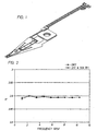
- liquid crystal polymer suspension assembly of the present invention having an overall thickness of approximately 2.1 mils (54 microns ( ⁇ )); i.e., 18 ⁇ stainless steel, 18 ⁇ liquid crystal polymer, and 18 ⁇ copper.
- thermotropic balanced liquid crystal polymer film (FA-100 from Kuraray Co., Ltd, Osaka, Japan) can be extruded by blown film extrusion.
- the liquid crystal polymer film is then disposed between a 0.7 mil (18 ⁇ ) thick sheet of A.S.T.M. 302 stainless steel and a 0.7 mil (18 ⁇ ) thick A.S.T.M. C 7025 copper alloy foil to form a stack.
- the stack can then be laminated in a press (flat bed) lamination process where the stack is placed in the press and compressed to about 100 psi. Once at 100 psi, the stack is heated to a temperature of about 295°C, and then further compressed to a pressure of about 500 psi. The laminate is held at 295 °C and 500 psi for at least 5 minutes prior to being cooled to room temperature and then removed from the press.
- the lamination process causes the liquid crystal polymer film to melt and adhere to both the stainless steel and copper alloy foil. In preparation for creating a circuit from the laminate, it is first cleaned using conventional techniques.
- the cleaned laminate is then coated on both the stainless steel and the copper alloy foil sides, with a photoresist which essentially masks these layers from etchant.
- the photoresist can be applied to the structure by hot rolling Riston 4106 dry film resist onto the structure and laminating at a temperature of 105°C and pressure of 30 psi in order to bond the photoresist to the structure.
- Areas of the photoresist are then selectively removed to expose the areas of the laminate to be etched.
- the photoresist layers are exposed to ultraviolet light at about 35 millijoules of energy in order to expose the area where the desired circuit pattern is to be located.
- the appropriate portions of the photoresist are then removed using conventional means such as an appropriate developing solution.
- the exposed photoresist laminate can then be etched using an etching solution comprised, for example, of up to about 75 weight percent (wt%) cupric chloride, up to about 5 wt% hydrochloric acid, and the balance deionized water, of about 39.0 to 44.0 wt% cupric chloride, about 3.20 to 4.00 wt% hydrochloric acid, balance deionized water; or another etching solution conventionally known in the art.
- the etching can occur at a temperature of about 50°C for a period of up to about 5 minutes, with less than 1 minute preferred.
- liquid crystal polymer dielectric must be selectively removed, another layer of Riston dry film photo resist is applied to both sides of the laminate, exposed to UV light (defining remaining liquid crystal polymer geometry), and then developed.
- This laminate could then be placed in a high vacuum plasma etcher (under appropriate temperature, pressure, and gas mix conditions) and have the liquid crystal polymer removed.
- protective plating such as nickel-gold, or tri-lead
- the following example can be used to form a liquid crystal polymer based suspension.
- An alternate suspension assembly could be made utilizing a liquid crystal polymer flex circuit material.
- a thin ( ⁇ 4 mils) unreinforced film based material that by nature is flexible.
- This assembly would consist of a liquid crystal polymer laminate with copper on one side having the circuit traces fabricated using traditional flex circuit processes, then having the entire circuit bonded to a stainless steel support.
- the magneto-resistive (MR) head would then be attached to the copper circuit in a secondary operation via traditional means.
- the stainless steel could be one of a number of grades (such as A.S.T.M. 302) and of the appropriate thickness (about 0.5 to about 2.0 mils) and width for the given geometries and loads.
- the main function of the stainless steel material is to support the mass of the flex material and magneto-resistive head at the appropriate distance from the rotating storage disk.
- the liquid crystal polymer laminate could consist of a liquid crystal polymer film material (such as FA-100 from Kuraray) being laminated to rolled copper (such as alloy 110 from Olin).
- the liquid crystal polymer thickness could range from about 0.4 to about 2.0 mils and the copper could range in thickness from about 0.1 to about 2.0 mils.
- the preferred thickness is about 0.7 to about 1.0 mils for the liquid crystal polymer, i.e.
- the liquid crystal polymer flex circuit could then be attached to the stainless steel with an adhesive such as epoxy resin or a single pressure sensitive adhesive (PSA).
- an adhesive such as epoxy resin or a single pressure sensitive adhesive (PSA).
- the advantage of this approach is that the trace circuitry (those conductive elements etched in the copper foil on the liquid crystal polymer) are created using industry standard flex circuit making techniques. This can be a low cost, high volume process.
- the advantage of a liquid crystal polymer flex material is that it will provide improved dimensional and electrical performance over a wide range of environmental conditions, thereby improving the device's reliability.
- the following table compares a liquid crystal film assembly versus a conventional polyimide film.
- the liquid crystal polymer material showed substantially improved hygrothermal properties (water absorption of only 0.04 versus 2.90 for the polyimide and coefficient of water absorbing expansion of 4 versus 12 to 22 for the polyimide), improved dielectric properties when exposed to humidity (volume and surface resistivity), and a seventy percent improvement in bending performance.
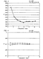
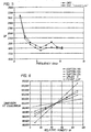
- Figures 2-5 which set forth the liquid crystal polymer assembly dielectric constant versus frequency under dry conditions and under 50% relative humidity at 23°C ( Figures 2 and 3), and dielectric constant versus frequency under dry conditions and after immersion in water at 50°C for 9 days ( Figures 4 and 5).
- the dielectric constant essentially did not vary at 50% relative humidity and only varied slightly after immersion in water for 9 days.
- Figure 6 shows the dimension at equilibrium versus relative humidity for a polyimide assembly. As is evident from this Figure, the dimension at equilibrium varied significantly with relative humidity.
- the rotatable storage device suspension assembly of the present invention possesses a significantly improved resistance to hygrothermal fluctuation compared to conventional polyimide based suspension assemblies, improved dimensional stability due to tailorable coefficient of thermal expansion and low modulus which allows the stainless steel to dominate the laminate modulus, and excellent environmental resistance. Furthermore, when the balanced liquid crystal polymer is employed, the assembly has more uniform properties (compared to unbalanced liquid crystal polymer laminates) improving the ease of manufacture of the circuits themselves.
- the assembly of the present invention has a low coefficient of hygrothermal expansion (CHE) typically less than about 10 parts per million per percent relative humidity (ppm/%RH), with less than about 5 ppm/%RH preferred, while conventional assemblies have a CHE exceeding about 20 ppm/%RH.
- CHE hygrothermal expansion
- the assembly of the present invention has a low coefficient of thermal expansion, i.e., about 1.5/1 or less (the flow direction versus the direction perpendicular thereto); and a dielectric constant which is substantially constant with changes in humidity.
- the unique suspension assembly of the present invention is hygrothermally stable, possesses a substantially constant coefficient of thermal expansion in both the flow direction and the direction perpendicular thereto, and has a dielectric constant (DK) which is substantially unaffected by changes in humidity.
Landscapes
- Supporting Of Heads In Record-Carrier Devices (AREA)
- Liquid Crystal Substances (AREA)
- Laminated Bodies (AREA)
- Adjustment Of The Magnetic Head Position Track Following On Tapes (AREA)
Applications Claiming Priority (3)
| Application Number | Priority Date | Filing Date | Title |
|---|---|---|---|
| US10521298P | 1998-10-22 | 1998-10-22 | |
| US105212P | 1998-10-22 | ||
| PCT/US1999/023374 WO2000023987A1 (en) | 1998-10-22 | 1999-10-07 | Liquid crystal polymer disk drive suspension assembly |
Publications (2)
| Publication Number | Publication Date |
|---|---|
| EP1125289A1 EP1125289A1 (en) | 2001-08-22 |
| EP1125289B1 true EP1125289B1 (en) | 2003-03-05 |
Family
ID=22304638
Family Applications (1)
| Application Number | Title | Priority Date | Filing Date |
|---|---|---|---|
| EP99953087A Expired - Lifetime EP1125289B1 (en) | 1998-10-22 | 1999-10-07 | Liquid crystal polymer disk drive suspension assembly |
Country Status (8)
| Country | Link |
|---|---|
| US (1) | US6356414B1 (enExample) |
| EP (1) | EP1125289B1 (enExample) |
| JP (1) | JP2002528833A (enExample) |
| CN (1) | CN1324562C (enExample) |
| AT (1) | ATE233936T1 (enExample) |
| AU (1) | AU6510599A (enExample) |
| DE (1) | DE69905743T2 (enExample) |
| WO (1) | WO2000023987A1 (enExample) |
Families Citing this family (7)
| Publication number | Priority date | Publication date | Assignee | Title |
|---|---|---|---|---|
| US6867948B1 (en) * | 1999-01-22 | 2005-03-15 | Seagate Technology Llc | Disc drives having flexible circuits with liquid crystal polymer dielectric |
| US6480359B1 (en) | 2000-05-09 | 2002-11-12 | 3M Innovative Properties Company | Hard disk drive suspension with integral flexible circuit |
| JP4156203B2 (ja) * | 2000-05-22 | 2008-09-24 | 株式会社日立グローバルストレージテクノロジーズ | ディスク装置用サスペンション |
| US6696163B2 (en) | 2000-07-18 | 2004-02-24 | 3M Innovative Properties Company | Liquid crystal polymers for flexible circuits |
| JP3915735B2 (ja) * | 2003-05-15 | 2007-05-16 | Tdk株式会社 | サスペンション、該サスペンションを備えたヘッドジンバルアセンブリ及び該ヘッドジンバルアセンブリを備えたディスクドライブ装置 |
| US8395865B2 (en) * | 2006-01-10 | 2013-03-12 | Seagate Technology Llc | Thermally insulated suspension load beam |
| US8213120B2 (en) * | 2007-09-10 | 2012-07-03 | International Business Machines Corporation | Flexible cable comprising liquid crystal polymer |
Family Cites Families (36)
| Publication number | Priority date | Publication date | Assignee | Title |
|---|---|---|---|---|
| US4543295A (en) | 1980-09-22 | 1985-09-24 | The United States Of America As Represented By The Director Of The National Aeronautics And Space Administration | High temperature polyimide film laminates and process for preparation thereof |
| US4624872A (en) | 1984-08-13 | 1986-11-25 | Celanese Corporation | Liquid crystalline polymer substrates with orthogonal molecular orientation |
| JPS6190343A (ja) | 1984-10-09 | 1986-05-08 | Polyplastics Co | 光ディスク |
| JPS61285249A (ja) | 1985-06-12 | 1986-12-16 | Polyplastics Co | 歯車用樹脂組成物 |
| JPH0623349B2 (ja) | 1986-01-30 | 1994-03-30 | 富士高分子工業株式会社 | 異方導電性接着剤 |
| US5833877A (en) | 1987-07-27 | 1998-11-10 | Elliott; Stanley B. | Reaction products of lyotropic liquid crystal salt complexes |
| US5443753A (en) | 1987-07-27 | 1995-08-22 | Elliott; Stanley B. | Reaction products of lyotropic liquid crystal salt complexes |
| JPS6431835A (en) | 1987-07-28 | 1989-02-02 | Kuraray Co | Fiber-reinforced polymer molded article |
| JPH01193388A (ja) | 1987-10-09 | 1989-08-03 | Agency Of Ind Science & Technol | リオトロピック液晶セル |
| US4991045A (en) * | 1987-12-21 | 1991-02-05 | Hutchinson Technology, Inc. | Suspension assembly |
| JPH0759635B2 (ja) | 1988-04-12 | 1995-06-28 | 日本石油株式会社 | サーモトロピック・コレステリック液晶性ポリペプチド |
| JP2621921B2 (ja) | 1988-05-10 | 1997-06-18 | 旭化成工業株式会社 | フイルムの製造方法 |
| JPH0663448B2 (ja) | 1988-07-15 | 1994-08-22 | 日本石油化学株式会社 | 消音器 |
| JPH02136292A (ja) | 1988-11-16 | 1990-05-24 | Ricoh Co Ltd | 感熱転写記録媒体 |
| GB8902581D0 (en) | 1989-02-06 | 1989-03-22 | Telephone Cables Ltd | Optical fibre cable core |
| US5142390A (en) | 1989-02-23 | 1992-08-25 | Ricoh Company, Ltd. | MIM element with a doped hard carbon film |
| DE69033139T2 (de) | 1990-09-28 | 1999-10-28 | Daicel Chemical Industries, Ltd. | Verbund-metallplatte |
| JPH04293787A (ja) | 1991-03-20 | 1992-10-19 | Toray Ind Inc | 表面金属化液晶ポリマ樹脂成形品の製造方法 |
| JP3024235B2 (ja) | 1991-03-20 | 2000-03-21 | 東レ株式会社 | 表面金属化液晶性ポリマ樹脂成形品の製造方法 |
| US5145553A (en) | 1991-05-06 | 1992-09-08 | International Business Machines Corporation | Method of making a flexible circuit member |
| US5427848A (en) | 1991-05-06 | 1995-06-27 | International Business Machines Corporation | Stress balanced composite laminate material |
| JP3108793B2 (ja) | 1991-11-08 | 2000-11-13 | 日本石油化学株式会社 | サーモトロピック液晶ポリマー粒子混合物およびそれを用いる成形方法 |
| JP2501289B2 (ja) | 1993-07-16 | 1996-05-29 | インターナショナル・ビジネス・マシーンズ・コーポレイション | ヘッド・サスペンション・アセンブリおよびその製造方法 |
| JPH08180353A (ja) | 1994-05-25 | 1996-07-12 | Hutchinson Technol Inc | ディスク駆動サスペンションアセンブリのための積層構造体の製造方法及びその積層構造体、並びにサスペンションアセンブリ |
| US5771135A (en) | 1994-06-13 | 1998-06-23 | International Business Machines Corporation | Vibration damping system for head suspension assemblies |
| JP3375217B2 (ja) | 1994-10-14 | 2003-02-10 | 新日本石油化学株式会社 | 電気電子部品用封止材 |
| US5771568A (en) | 1995-03-02 | 1998-06-30 | Hutchinson Technology Incorporated | Method for manufacturing a head suspension having electrical trace interconnects with reduced capacitance |
| JPH08315532A (ja) | 1995-03-08 | 1996-11-29 | Hutchinson Technol Inc | 溶接応力の分離構造体を備えるヘッドサスペンションアセンブリ |
| US5666241A (en) | 1995-07-10 | 1997-09-09 | Magnecomp Corp. | Double dimple disk drive suspension |
| JP2986084B2 (ja) | 1995-10-12 | 1999-12-06 | インターナショナル・ビジネス・マシーンズ・コーポレイション | デイスク装置におけるサスペンション・アセンブリ構成及びその組立て方法 |
| JP3620751B2 (ja) | 1995-10-30 | 2005-02-16 | 住友ベークライト株式会社 | 異方導電フィルム |
| US5627704A (en) | 1996-02-12 | 1997-05-06 | Read-Rite Corporation | Thin film giant magnetoresistive CPP transducer with flux guide yoke structure |
| US5668684A (en) | 1996-08-06 | 1997-09-16 | International Business Machines Corporation | Electrical interconnect for a head/arm assembly of computer disk drives |
| GB9617885D0 (en) | 1996-08-28 | 1996-10-09 | Philips Electronics Nv | Electronic device manufacture |
| US5731401A (en) | 1996-09-30 | 1998-03-24 | Hoechst Celanese Corp. | Process for the preparation of thermotropic aromatic polyesters directly from dialkyl aromatic esters |
| US6046886A (en) | 1997-10-09 | 2000-04-04 | Seagate Technology, Inc. | Flex circuit head interconnect with insulating spacer |
-
1999
- 1999-10-05 US US09/413,221 patent/US6356414B1/en not_active Expired - Lifetime
- 1999-10-07 DE DE69905743T patent/DE69905743T2/de not_active Expired - Fee Related
- 1999-10-07 WO PCT/US1999/023374 patent/WO2000023987A1/en not_active Ceased
- 1999-10-07 JP JP2000577654A patent/JP2002528833A/ja active Pending
- 1999-10-07 CN CNB998123315A patent/CN1324562C/zh not_active Expired - Fee Related
- 1999-10-07 AU AU65105/99A patent/AU6510599A/en not_active Abandoned
- 1999-10-07 AT AT99953087T patent/ATE233936T1/de not_active IP Right Cessation
- 1999-10-07 EP EP99953087A patent/EP1125289B1/en not_active Expired - Lifetime
Also Published As
| Publication number | Publication date |
|---|---|
| ATE233936T1 (de) | 2003-03-15 |
| WO2000023987A1 (en) | 2000-04-27 |
| CN1324562C (zh) | 2007-07-04 |
| WO2000023987A9 (en) | 2002-08-22 |
| EP1125289A1 (en) | 2001-08-22 |
| JP2002528833A (ja) | 2002-09-03 |
| DE69905743D1 (de) | 2003-04-10 |
| CN1324479A (zh) | 2001-11-28 |
| AU6510599A (en) | 2000-05-08 |
| DE69905743T2 (de) | 2003-12-24 |
| US6356414B1 (en) | 2002-03-12 |
Similar Documents
| Publication | Publication Date | Title |
|---|---|---|
| US20040247921A1 (en) | Etched dielectric film in hard disk drives | |
| US6735052B2 (en) | Hard disk drive suspension with integral flexible circuit | |
| US5427848A (en) | Stress balanced composite laminate material | |
| JP4312817B2 (ja) | Hddサスペンション用積層体及びその製造方法 | |
| EP0786928B1 (en) | Novel flexible copper-coated laminate and flexible printed circuit board | |
| US6296949B1 (en) | Copper coated polyimide with metallic protective layer | |
| US6574075B2 (en) | Liquid crystal polymer disk drive suspension assembly and method of manufacture thereof | |
| KR20010105375A (ko) | 다중-층 인쇄 회로를 위한 적층 | |
| EP1125289B1 (en) | Liquid crystal polymer disk drive suspension assembly | |
| JP2711005B2 (ja) | 動的屈曲領域を有する多層回路の製造方法及び該方法により製造されたフレキシブル回路 | |
| JP4086768B2 (ja) | フレキシブル回路用基板の製造方法 | |
| US4945029A (en) | Process for the manufacture of multi-layer circuits with dynamic flexing regions and the flexible circuits made therefrom | |
| EP0675673A2 (en) | Reinforcement for flexible printed circuit board and reinforced flexible circuit board | |
| JP4004139B2 (ja) | 多層積層板とその製造方法および多層実装回路基板 | |
| US6001489A (en) | Flexible printed circuit and process for producing the same | |
| JP3502502B2 (ja) | 回路形成用基板および回路基板 | |
| JP3418709B2 (ja) | プリント回路基板の構成部品 | |
| WO2005096299A1 (ja) | Hddサスペンション用積層体およびその製造方法 | |
| US7361979B2 (en) | Multi-sheet conductive substrates for microelectronic devices and methods for forming such substrates | |
| Pawlowski | Polyimide Considerations in Thin-Film Electronic Packaging | |
| JP2002252450A (ja) | カバーレイフィルム | |
| JPH10242605A (ja) | フレキシブル配線板 | |
| JPS61132339A (ja) | 金属プリント基板 | |
| KR20070021159A (ko) | 하드 디스크 드라이브 내의 에칭된 유전 필름 | |
| MXPA06009604A (es) | Pelicula dielectrica grabada en unidades de disco duro |
Legal Events
| Date | Code | Title | Description |
|---|---|---|---|
| PUAI | Public reference made under article 153(3) epc to a published international application that has entered the european phase |
Free format text: ORIGINAL CODE: 0009012 |
|
| 17P | Request for examination filed |
Effective date: 20010419 |
|
| AK | Designated contracting states |
Kind code of ref document: A1 Designated state(s): AT BE CH CY DE DK ES FI FR GB GR IE IT LI LU MC NL PT SE |
|
| GRAG | Despatch of communication of intention to grant |
Free format text: ORIGINAL CODE: EPIDOS AGRA |
|
| 17Q | First examination report despatched |
Effective date: 20011213 |
|
| GRAG | Despatch of communication of intention to grant |
Free format text: ORIGINAL CODE: EPIDOS AGRA |
|
| GRAH | Despatch of communication of intention to grant a patent |
Free format text: ORIGINAL CODE: EPIDOS IGRA |
|
| GRAH | Despatch of communication of intention to grant a patent |
Free format text: ORIGINAL CODE: EPIDOS IGRA |
|
| GRAA | (expected) grant |
Free format text: ORIGINAL CODE: 0009210 |
|
| AK | Designated contracting states |
Designated state(s): AT BE CH CY DE DK ES FI FR GB GR IE IT LI LU MC NL PT SE |
|
| PG25 | Lapsed in a contracting state [announced via postgrant information from national office to epo] |
Ref country code: NL Free format text: LAPSE BECAUSE OF FAILURE TO SUBMIT A TRANSLATION OF THE DESCRIPTION OR TO PAY THE FEE WITHIN THE PRESCRIBED TIME-LIMIT Effective date: 20030305 Ref country code: LI Free format text: LAPSE BECAUSE OF FAILURE TO SUBMIT A TRANSLATION OF THE DESCRIPTION OR TO PAY THE FEE WITHIN THE PRESCRIBED TIME-LIMIT Effective date: 20030305 Ref country code: IT Free format text: LAPSE BECAUSE OF FAILURE TO SUBMIT A TRANSLATION OF THE DESCRIPTION OR TO PAY THE FEE WITHIN THE PRESCRIBED TIME-LIMIT;WARNING: LAPSES OF ITALIAN PATENTS WITH EFFECTIVE DATE BEFORE 2007 MAY HAVE OCCURRED AT ANY TIME BEFORE 2007. THE CORRECT EFFECTIVE DATE MAY BE DIFFERENT FROM THE ONE RECORDED. Effective date: 20030305 Ref country code: GR Free format text: LAPSE BECAUSE OF FAILURE TO SUBMIT A TRANSLATION OF THE DESCRIPTION OR TO PAY THE FEE WITHIN THE PRESCRIBED TIME-LIMIT Effective date: 20030305 Ref country code: FI Free format text: LAPSE BECAUSE OF FAILURE TO SUBMIT A TRANSLATION OF THE DESCRIPTION OR TO PAY THE FEE WITHIN THE PRESCRIBED TIME-LIMIT Effective date: 20030305 Ref country code: CH Free format text: LAPSE BECAUSE OF FAILURE TO SUBMIT A TRANSLATION OF THE DESCRIPTION OR TO PAY THE FEE WITHIN THE PRESCRIBED TIME-LIMIT Effective date: 20030305 Ref country code: BE Free format text: LAPSE BECAUSE OF FAILURE TO SUBMIT A TRANSLATION OF THE DESCRIPTION OR TO PAY THE FEE WITHIN THE PRESCRIBED TIME-LIMIT Effective date: 20030305 Ref country code: AT Free format text: LAPSE BECAUSE OF FAILURE TO SUBMIT A TRANSLATION OF THE DESCRIPTION OR TO PAY THE FEE WITHIN THE PRESCRIBED TIME-LIMIT Effective date: 20030305 |
|
| REG | Reference to a national code |
Ref country code: GB Ref legal event code: FG4D |
|
| REG | Reference to a national code |
Ref country code: CH Ref legal event code: EP |
|
| REG | Reference to a national code |
Ref country code: IE Ref legal event code: FG4D |
|
| REF | Corresponds to: |
Ref document number: 69905743 Country of ref document: DE Date of ref document: 20030410 Kind code of ref document: P |
|
| PG25 | Lapsed in a contracting state [announced via postgrant information from national office to epo] |
Ref country code: SE Free format text: LAPSE BECAUSE OF FAILURE TO SUBMIT A TRANSLATION OF THE DESCRIPTION OR TO PAY THE FEE WITHIN THE PRESCRIBED TIME-LIMIT Effective date: 20030605 Ref country code: PT Free format text: LAPSE BECAUSE OF FAILURE TO SUBMIT A TRANSLATION OF THE DESCRIPTION OR TO PAY THE FEE WITHIN THE PRESCRIBED TIME-LIMIT Effective date: 20030605 Ref country code: DK Free format text: LAPSE BECAUSE OF FAILURE TO SUBMIT A TRANSLATION OF THE DESCRIPTION OR TO PAY THE FEE WITHIN THE PRESCRIBED TIME-LIMIT Effective date: 20030605 |
|
| NLV1 | Nl: lapsed or annulled due to failure to fulfill the requirements of art. 29p and 29m of the patents act | ||
| REG | Reference to a national code |
Ref country code: CH Ref legal event code: PL |
|
| PG25 | Lapsed in a contracting state [announced via postgrant information from national office to epo] |
Ref country code: ES Free format text: LAPSE BECAUSE OF FAILURE TO SUBMIT A TRANSLATION OF THE DESCRIPTION OR TO PAY THE FEE WITHIN THE PRESCRIBED TIME-LIMIT Effective date: 20030930 |
|
| PG25 | Lapsed in a contracting state [announced via postgrant information from national office to epo] |
Ref country code: LU Free format text: LAPSE BECAUSE OF NON-PAYMENT OF DUE FEES Effective date: 20031007 Ref country code: IE Free format text: LAPSE BECAUSE OF NON-PAYMENT OF DUE FEES Effective date: 20031007 Ref country code: CY Free format text: LAPSE BECAUSE OF FAILURE TO SUBMIT A TRANSLATION OF THE DESCRIPTION OR TO PAY THE FEE WITHIN THE PRESCRIBED TIME-LIMIT Effective date: 20031007 |
|
| ET | Fr: translation filed | ||
| PG25 | Lapsed in a contracting state [announced via postgrant information from national office to epo] |
Ref country code: MC Free format text: LAPSE BECAUSE OF NON-PAYMENT OF DUE FEES Effective date: 20031031 |
|
| PLBE | No opposition filed within time limit |
Free format text: ORIGINAL CODE: 0009261 |
|
| STAA | Information on the status of an ep patent application or granted ep patent |
Free format text: STATUS: NO OPPOSITION FILED WITHIN TIME LIMIT |
|
| 26N | No opposition filed |
Effective date: 20031208 |
|
| REG | Reference to a national code |
Ref country code: IE Ref legal event code: MM4A |
|
| PGFP | Annual fee paid to national office [announced via postgrant information from national office to epo] |
Ref country code: DE Payment date: 20061130 Year of fee payment: 8 |
|
| PG25 | Lapsed in a contracting state [announced via postgrant information from national office to epo] |
Ref country code: DE Free format text: LAPSE BECAUSE OF NON-PAYMENT OF DUE FEES Effective date: 20080501 |
|
| REG | Reference to a national code |
Ref country code: FR Ref legal event code: ST Effective date: 20080630 |
|
| PGFP | Annual fee paid to national office [announced via postgrant information from national office to epo] |
Ref country code: FR Payment date: 20061017 Year of fee payment: 8 |
|
| PG25 | Lapsed in a contracting state [announced via postgrant information from national office to epo] |
Ref country code: FR Free format text: LAPSE BECAUSE OF NON-PAYMENT OF DUE FEES Effective date: 20071031 |
|
| PGFP | Annual fee paid to national office [announced via postgrant information from national office to epo] |
Ref country code: GB Payment date: 20141027 Year of fee payment: 16 |
|
| GBPC | Gb: european patent ceased through non-payment of renewal fee |
Effective date: 20151007 |
|
| PG25 | Lapsed in a contracting state [announced via postgrant information from national office to epo] |
Ref country code: GB Free format text: LAPSE BECAUSE OF NON-PAYMENT OF DUE FEES Effective date: 20151007 |