EP1124309B1 - Positionsdetektor von magnetischen Polen - Google Patents
Positionsdetektor von magnetischen Polen Download PDFInfo
- Publication number
- EP1124309B1 EP1124309B1 EP01103015A EP01103015A EP1124309B1 EP 1124309 B1 EP1124309 B1 EP 1124309B1 EP 01103015 A EP01103015 A EP 01103015A EP 01103015 A EP01103015 A EP 01103015A EP 1124309 B1 EP1124309 B1 EP 1124309B1
- Authority
- EP
- European Patent Office
- Prior art keywords
- rotor
- plates
- magnetic
- pole position
- detecting device
- Prior art date
- Legal status (The legal status is an assumption and is not a legal conclusion. Google has not performed a legal analysis and makes no representation as to the accuracy of the status listed.)
- Expired - Lifetime
Links
- 230000004907 flux Effects 0.000 claims description 25
- 239000000696 magnetic material Substances 0.000 claims description 16
- 230000004044 response Effects 0.000 claims description 3
- 238000010586 diagram Methods 0.000 description 5
- 229910000576 Laminated steel Inorganic materials 0.000 description 4
- 230000000694 effects Effects 0.000 description 4
- 238000010276 construction Methods 0.000 description 2
- 238000001514 detection method Methods 0.000 description 2
- 230000002093 peripheral effect Effects 0.000 description 2
- 230000001360 synchronised effect Effects 0.000 description 2
- 230000008859 change Effects 0.000 description 1
- 239000012141 concentrate Substances 0.000 description 1
- 230000003993 interaction Effects 0.000 description 1
- 230000004048 modification Effects 0.000 description 1
- 238000012986 modification Methods 0.000 description 1
- 230000010363 phase shift Effects 0.000 description 1
Images






Classifications
-
- H—ELECTRICITY
- H02—GENERATION; CONVERSION OR DISTRIBUTION OF ELECTRIC POWER
- H02K—DYNAMO-ELECTRIC MACHINES
- H02K29/00—Motors or generators having non-mechanical commutating devices, e.g. discharge tubes or semiconductor devices
- H02K29/06—Motors or generators having non-mechanical commutating devices, e.g. discharge tubes or semiconductor devices with position sensing devices
- H02K29/08—Motors or generators having non-mechanical commutating devices, e.g. discharge tubes or semiconductor devices with position sensing devices using magnetic effect devices, e.g. Hall-plates, magneto-resistors
-
- H—ELECTRICITY
- H02—GENERATION; CONVERSION OR DISTRIBUTION OF ELECTRIC POWER
- H02K—DYNAMO-ELECTRIC MACHINES
- H02K1/00—Details of the magnetic circuit
- H02K1/06—Details of the magnetic circuit characterised by the shape, form or construction
- H02K1/22—Rotating parts of the magnetic circuit
- H02K1/27—Rotor cores with permanent magnets
- H02K1/2706—Inner rotors
- H02K1/272—Inner rotors the magnetisation axis of the magnets being perpendicular to the rotor axis
- H02K1/274—Inner rotors the magnetisation axis of the magnets being perpendicular to the rotor axis the rotor consisting of two or more circumferentially positioned magnets
- H02K1/2753—Inner rotors the magnetisation axis of the magnets being perpendicular to the rotor axis the rotor consisting of two or more circumferentially positioned magnets the rotor consisting of magnets or groups of magnets arranged with alternating polarity
- H02K1/276—Magnets embedded in the magnetic core, e.g. interior permanent magnets [IPM]
- H02K1/2766—Magnets embedded in the magnetic core, e.g. interior permanent magnets [IPM] having a flux concentration effect
Definitions
- This invention relates to detecting the position of a magnetic pole of a motor by use of a magnetic sensor.
- Tokkai Hei 11-215881 published by the Japanese Patent Office in 1999 discloses a magnetic pole position detector of a brushless DC motor.
- the detector is provided with a disk which rotates together with a rotor of the motor.
- the rotor is provided with four magnets so as to form four magnetic poles.
- the outer periphery of the disk is also magnetized to have four magnetic poles.
- Three Hall integrated circuits facing the outer periphery of the disk detect variations in a magnetic flux resulting from the rotation of the disk and output a signal indicating the rotation position of magnetic poles.
- US-A-5 864 192 discloses a brushless motor that includes a stator and a rotor rotably supported inside the stator according to the pre-characterized part of independent claim 1.
- a device which detects the magnetic flux of a magnet of the rotor directly using a Hall integrated circuit.
- the Hall integrated circuit is disposed adjacent to the rotor in an axial direction and outputs positive or negative signals in response to the leakage flux of the magnetic poles.
- Leakage flux is magnetic flux which is not directed towards the coils of the stator, that is to say, magnetic flux not applied to the rotation of the rotor.
- the object is achieved by a magnet pole position detecting device according to claim 1.
- a magnet pole position detector for such a rotor that has a plurality of magnets disposed on a circular periphery, and rotates with a rotation shaft.
- the detector comprises plates of the same number as the magnets and a magnetic sensor.
- the plates are made of a magnetic material.
- Each of the plates is disposed on the rotor at a position along a circular path nearby a corresponding magnet and magnetized by leakage flux of the corresponding magnet.
- the magnetic sensor outputs a signal in response to a variation of a magnetic flux density on the circular path.
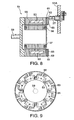
- FIG. 1 is a schematic diagram of a magnetic pole position detector of a rotor according to this invention.
- FIG. 2A and FIG. 2B are a cross-sectional view of the rotor and a linearized cross-sectional view of plates made of magnetic materials according to this invention.
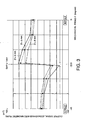
- FIG. 3 is a diagram of an output signal of a magnetic sensor with respect to a distance from an end face of the rotor to the magnetic sensor, according to this invention.
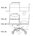
- FIGs. 4A - 4D are diagrams showing a rectangular wave signal with respect to positions of the plates, positions of the magnets, and an output signal of the magnetic sensor, according to this invention.
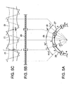
- FIGs. 5A - 5C are diagrams showing output signals of three magnetic sensors that are disposed to face the end face of the rotor, according to this invention.
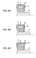
- FIGs. 6A - 6C are longitudinal cross-sectional views of the main components of the rotor showing variations in the disposition of the plates, according to this invention.
- FIG. 7 is a cross-sectional view of the rotor according to a second embodiment of this invention.
- FIG. 8 is a schematic diagram of the magnetic pole position detector according to a third embodiment of this invention.
- FIG. 9 is a cross-sectional view of an outer rotor according to the third embodiment of this invention.
- FIGs. 10A and 10B are enlarged longitudinal-sectional views of the main components of the rotor showing alternative constructions of the end face of the rotor, according to this invention.
- FIGs. 11A - 11D are enlarged longitudinal-sectional views of the main components of the rotor showing alternative constructions of the rotor, according to this invention.
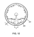
- FIG. 12 is a cross-sectional view of the rotor according to a fourth embodiment of this invention.
- FIG. 13 is a front view of a disk according to a fifth embodiment of this invention.
- FIG. 14 is a longitudinal-sectional view of the rotor and a stator according to a sixth embodiment of this invention.
- FIG. 15 is a cross-sectional view of the rotor taken along the line XV - XV in FIG. 14 .
- a synchronous motor 13 is provided with a rotor 17, a rotation shaft 21 of the rotor 17 and a stator 19 which has a plurality of coils 26 facing an outer periphery of the rotor 17.
- the rotor 17 is provided with magnets 15 which have four pairs of magnetic poles disposed alternatively at equal angular intervals.
- the magnets 15 are invoked to follow the rotating magnetic fields and, as a result, the rotor 17 rotates in synchronism with the rotating magnetic fields.
- the N poles and S poles of the magnets 15 shown in FIG. 2A express the polarity of the magnets 15 on the outer periphery of the rotor 17 facing the stator 19.
- an end plate 23 of a non-magnetic body is fixed to an axial end of the rotor 17.
- Plates 25 made of magnetic materials are recessed on the end plate 23 as shown in FIG. 2A at positions corresponding to the respective magnets 15.
- a predetermined space is provided between adjacent plates 25.
- the central axis of these spaces coincides with a straight line connecting the center of the rotor 17 and the middle point of two magnets 15.
- a non-magnetic body may be sandwiched between the plates 25 instead of the space.
- the plates 25 displace on a circular path on an axial end face of the rotor 17 together with the rotation of the rotor 17 as shown in FIG. 2A .
- Magnetic sensors 27 are fixed at three positions on a case 13A of the motor 13 facing the circular path. Hall integrated circuits, MR circuit elements or GMR circuit elements may be used for example as the magnetic sensors 27.
- the output signal of the magnetic sensors 27 is output to a drive device (not shown) of the motor.
- the drive device detects a magnetic pole position on the basis of this signal and generates a polyphase alternating current corresponding to a torque applied to each magnet 15. This alternating current is supplied to the coils 26 of the stator 19.
- FIG. 2B shows the plates 25 that are linearized for the explanatory reason.
- Leakage flux of the magnet 15 magnetizes the plate 25 when close to the magnet 15. Since adjacent magnets 15 have different polarity, the interaction of adjacent plates 25 results in a magnetic flux being concentrated on the end of the plate 25.
- FIG. 3 shows the relationship between the distance D from the axial end face of the rotor 17 to the magnetic sensor 27 and a signal output by the magnetic sensor 27 as measured in a synchronous motor comprising four pairs of magnetic poles as described above.
- the voltage signal output by the magnetic sensor 27 is converted to a flux density and expressed in units of milletesla (mT).
- the figure shows variation in the output signal when the distance D from the axial end face of the rotor 17 to the magnetic sensor 27 is taken to be 3 mm, 5 mm and 8 mm respectively.
- the voltage signal output by the magnetic sensor 27 has a value of 0 mT in the figure at the point P where the mechanical angle ⁇ between the S pole and the N pole equals 22.5 degrees.
- the voltage signal displays sharp variation on either side of the point P.
- the output signal of the magnetic sensor 27 has a maximum positive value when facing the end of the plate 25 which corresponds to the N pole of the magnet 15. Conversely the output signal of the magnetic sensor 27 has a maximum negative value when facing the end of the plate 25 which corresponds to the S pole of the magnet 15.
- the output signal of the magnetic sensor 27 undergoes sharp variation on the border with the point P.
- the output wave of a prior art magnetic sensor was sinusoidal.
- the output of the magnetic sensor of the magnetic pole position detector according to this invention undergoes sharp variation when it passes the space between the plates 25. In other words, the output takes a maximum value near the border of the plates 25. The accuracy of detecting a pole position is therefore ensured even if there are fluctuations in the performance of the magnetic sensor 27 or deviations in the output voltage signal thereof.
- the output signal of the magnetic sensor 27 undergoes sharp variation at intervals of an electrical angle of 180 degrees as shown in FIG. 4C when passing the space between the plates 25.
- a rectangular wave signal is obtained as shown in FIG. 4D by comparing this signal in a comparator with a predetermined value.
- An electrical angle is an angle obtained when one variation cycle of the output signal of the magnetic sensor 27 is taken to have a value of 360 degrees. Since the rotor 17 has four pairs of magnetic poles, a single rotation of the rotor 17 corresponds to four cycles of the output signal of the magnetic sensor 27. Thus an electrical angle of 360 degrees corresponds to a mechanical angle of 90 degrees.
- FIGs. 5A - 5C it is possible to discriminate magnetic pole positions at intervals of an electrical angle of 60 degrees from the output signal of the three magnetic sensors 27 due to the disposition of magnetic sensors 27 at 30-degree intervals at the three positions (1), (2), (3) facing the circular path of the plates 25.
- the output signal of the magnetic sensor 27 is affected by the exciting current supplied to the coils 26 of the stator 19.
- the characteristic feature of the output signal of the magnetic sensor 27, i.e., a sharp variation about the border of the adjacent plates 25, does not change under the effect of the exciting current of the coils 26.
- the length of the plate 25 in the peripheral direction of the rotor 17 is set to be longer than that of the magnet 15. This setting plays an important role to produce a sharp variation of the output signal of the magnetic sensor 27 about the border of the adjacent plates 25. The accuracy of detecting magnetic pole positions is thus ensured under the effect of the exciting current of the coils 26.
- each of the plates 25 is recessed on the end plate 23.
- the plate 25 may be disposed in various ways in this invention.
- the plate 25 may be fixed on the end plate 23.
- half of the plate 25 may be recessed in the end plate 23.
- the plate 25C may be fixed to an outer edge of the end plate 23. If the plate 25C is lengthened in the direction of the rotation shaft 21 as shown in the figure, it is possible to dispose the magnetic sensor 27 on an outer side of the rotor 17.
- the magnetic pole position detector of this invention As described above, according to the magnetic pole position detector of this invention, a magnetic loop is concentrated on both ends of the plate 25, the phase shift of the output signal of the magnetic sensor 27 is not likely to occur, so the detection of the position of the magnetic poles of the rotor 17 is always performed with accuracy.
- FIG. 7 A second embodiment of this invention will be described referring to FIG. 7 .
- This embodiment differs from the first embodiment only with respect to the structure of the rotor.
- the rotor 31 in this embodiment is provided with plates 33 made of magnetic materials on an inner periphery of the axial end face.
- the plate 33 is formed in the shape of a letter "T".
- the vertical section of the letter "T” reaches an outer periphery of the rotor in a radial direction.
- This part functions as a magnetic passage 35 transmitting the magnetic flux of the magnet 15 to the plate 33.
- the horizontal section of the letter "T" is slightly arc-shaped. The distance between the horizontal section and the rotation shaft 21 is set shorter than the distance between the corresponding magnet 15 and the rotation shaft 21.
- the magnetic sensor is disposed to face a circular path on which the horizontal sections of the plates 33 travel.
- this embodiment disposes the plates 33 at a position away from the stator, it is possible to reduce the effect of the exciting current in the stator coils on the output current of the magnetic sensor.
- FIGs. 8 and 9 a magnetic pole position detector of the motor 51 according to a third embodiment of this invention will be described referring to FIGs. 8 and 9 .
- the motor 51 is provided with an outer rotor 55 having magnets 53 and a rotation shaft 59, and a stator 57 provided with coils 56 and disposed on an inner side of the outer rotor 55.
- An end plate 61 of a non-magnetic body is fixed to an axial end of the outer rotor 55.
- a plate 63 in the shape of a letter "T" is fixed to the end plate 61.
- the horizontal section of the plate 63 is disposed along the outer periphery of the outer rotor 55 as shown in FIG. 9 .
- the vertical section of the plate 63 reaches an inner periphery of the outer rotor 55 along the end plate 61.
- the vertical section functions as a circuit 65 transmitting the magnetic flux of the magnet 53 to the horizontal section of the plate 63.
- the magnetic sensor 27 is disposed to face an axial end face of the outer rotor 55 at a position proximate to the outer periphery of the outer rotor 55.
- a magnetic sensor 27 is fixed to the case 51A of the motor 51 facing the circular path of the horizontal part of the plates 63 as the outer rotor 55 rotates.
- the horizontal part of the plates 63 in this embodiment is disposed along an outer periphery of the outer rotor 55 further from the stator 57 than the magnet 53, it is possible to dispose the magnetic sensor 27 at a position distant from the coils 56 of the stator 57, so the effect of the current flowing through the coils 64 on the magnetic sensor 27 is kept small.
- FIGs. 10A and 10B variations in the disposition of the plates with respect to the magnets will be described. These variations can be applied to any of the first to the third embodiments.
- a rotor 71 is provided with a laminated steel plates functioning as a rotor core 73. Magnets 75 are recessed in the core 73. Plates 77 made of magnetic materials are fixed to an axial end of the core 73. The plate 77 has a contacting part 79 that is fixed to the core 73 and functions as a magnetic passage that transmits the magnetic flux of the magnet 75 to the plate 77. Apart from the contacting part 79, a space 81 is formed between the plate 77 and the core 73. Another space 83 is formed between two adjacent plates 77.
- a rotor is provided with a non-magnetic body 93 recessed in the core 73 between the contacting part 79 and the magnet 75.
- An end plate 95 made of non-magnetic materials is provided between the core 73 and the plate 77.
- FIGs. 11A - 11D Further variations in the disposition of the plates will be described referring to FIGs. 11A - 11D .
- a rotor 101 is provided with a core 103 comprising laminated steel plates and with magnets 105 recessed in the core 103. Plates 107 made of magnetic materials are fixed to an axial end of the rotor 101 and respectively make contact with a corresponding magnet 105. Two adjacent plates 107 are separated by a space 109. A recess 111 is formed in the core 103 under the space 109. The recess 111 may be filled with a non-magnetic material. The width of the recess 111 is set to be wider than that of the space 109 while narrower than the distance between adjacent magnets 105.
- a rotor 121 is provided with a core 123 comprising laminated steed plates and with the magnets 105 recessed in the core 123.
- the magnets 105 are covered by the core 123.
- Plates 107 made of magnetic materials are fixed to the core 123 on an axial end of the rotor 121.
- Two adjacent plates 107 are separated by the space 109 and the recess 111 is formed in the core 103 under the space 109 in the same way as in the rotor 101 of FIG. 11A .
- a rotor 131 is provided with a core 133 comprising a laminated steel plates and with the magnets 105 recessed in the core 133.
- One axial end of the rotor 131 is covered by a non-magnetic plate 135.
- the plates 107 are disposed on one side of the non-magnetic plate 135 opposite to the magnets 105 so that the non-magnetic plate 135 is gripped between the plates 107 and the magnets 105. Two adjacent plates 107 are separated by the space 109.
- a rotor 141 is provided with a core 143 comprising laminated steel plates and with magnets 105 recessed in the core 143.
- the magnets 105 are covered by the core. 143.
- One axial end of the rotor 141 is covered by the non-magnetic plate 135 in the same way as the structure of FIG. 11C .
- the plates 107 are disposed on one side of the non-magnetic plate 135 opposite to the magnets 105. Two adjacent plates 107 are separated by the space 109.
- the magnetic flux loop is concentrated on both ends of the plate 107 by forming the space 109 between adjacent plates 107 or by disposing a non-magnetic body therebetween.
- a fourth embodiment of this invention will be described with reference to FIG. 12 .
- This embodiment differs from the other embodiments with respect to the disposition of the magnets on the rotor.
- pairs of two magnet components 210A, 210B of equal polarity are disposed on a rotor 201.
- Each pair of the magnet components 210A, 210B function as one magnet and the pairs of the magnet components 210A, 210B are disposed at fixed intervals.
- Plates 220 made of magnetic materials are disposed at positions corresponding to the respective pairs of the magnet components 210A, 210B on an axial end face of the rotor 201.
- the output signal of the magnetic sensor sharply varies when it passes a space between the plates 220 by setting the width X of the space between the plates 220 to be smaller than the width Y of the space between the pairs of magnet components 210A, 210B having different polarity.
- a fifth embodiment of this invention will be described with reference to FIG. 13 .
- This embodiment relates to the shape of the plates made of magnetic materials.
- the plates 25, 33, 63, 77, 107 and 220 used in the first to fourth embodiments are independent and are not in contact with each other.
- a disk 300 made of magnetic materials is divided into plate members 300A - 300H by forming radial grooves on the disk 300.
- the plate members 300A - 300H correspond to the single plates 25, 33, 63, 77, 107 and 220 in the first to fourth embodiments.
- the plate members 300A - 300H are in electrical contact with each other at a central section of the disk 300.
- the plate members 300A - 300H still concentrate the magnetic flux on both sides of the grooves 301. This is achieved by disposing the magnets of the rotor such that each of the grooves corresponds to the central point of the space between two adjacent magnets.
- the single disk 300 may replace the plates 25, 33, 63, 77, 107 and 220 of the first - fourth embodiments.
- FIG. 14 and FIG. 15 A sixth embodiment of this invention will be described with reference to FIG. 14 and FIG. 15 .
- a motor according to this embodiment is provided with a cylindrical rotor 401 and a stator 402 facing the rotor 401 from an axial direction.
- the stator 402 is fixed to the case 400A of the motor.
- the rotor 401 is provided with a cylindrical core 412, magnets 411 recessed at equal angular intervals in the core 412 as shown in FIG. 15 and a rotation shaft 410 extending in an opposite direction to the stator 402.
- the stator 402 is provided with coils 415 of the equal number to that of the magnets 411.
- the polarity of the magnets 411 facing the stator 402 alternates one by one in the peripheral direction of the rotor 401.
- a collar 420 made of non-magnetic materials is fitted on an outer periphery of the rotor 401.
- Plates 430 made of magnetic materials are fixed at equal angular intervals to the outer periphery of the end plate 420.
- the width of the space between adjacent plates 430 is set to be smaller than that of the space between adjacent magnets 411.
- a magnetic sensor (not shown) is provided on a position facing the outer periphery of the rotor 401. In this manner, this invention may be applied to a motor which aligns a rotor and a stator in an axial direction.
Landscapes
- Engineering & Computer Science (AREA)
- Power Engineering (AREA)
- Brushless Motors (AREA)
- Measurement Of Length, Angles, Or The Like Using Electric Or Magnetic Means (AREA)
- Transmission And Conversion Of Sensor Element Output (AREA)
- Permanent Magnet Type Synchronous Machine (AREA)
Claims (11)
- Magnetpolposition-Erfassungsvorrichtung, die einen Rotor (17, 31, 55, 71, 91, 101, 121, 131, 141, 201, 401), der eine Mehrzahl von Magneten (15, 53, 75, 105) umfasst, die auf einem kreisförmigen Umfang angeordnet sind, und mit einer Rotationswelle (21, 59) rotiert, und einen Magnetsensor umfasst, der als Antwort auf eine Änderung der magnetischen Flussdichte auf einer kreisförmigen Bahn ein Signal ausgibt:
gekennzeichnet durch
Platten (25, 25A, 25B, 25C, 33, 63, 77, 107, 220, 300A-300H, 430) in gleicher Anzahl wie die Magnete (15, 53, 75, 105), wobei die Platten (25, 25A, 25B, 25C, 33, 63, 77, 107, 220, 300A-300H, 430) aus einem magnetischen Material hergestellt sind, wobei jede der Platten (25, 25A, 25B, 25C, 33, 63, 77, 107, 220, 300A-300H, 430) auf dem Rotor (17, 31, 55, 71, 91, 101, 121, 131, 141, 201, 401) an einer Position entlang der kreisförmigen Bahn in der Nähe eines korrespondierenden Magneten (15, 53, 75, 105) angeordnet ist und durch den Streufluss des korrespondierenden Magneten (15, 53, 75, 105, 210A, 210B, 401) magnetisiert wird. - Magnetpolposition-Erfassungsvorrichtung gemäß Anspruch 1, wobei die Platten (25, 25A, 25B, 25C, 33, 63, 77, 107, 220, 300, 430) an beiden Enden der Platten (25, 25A, 25B, 25C, 33, 63, 77, 107, 220, 300A-300H, 430) auf der kreisförmigen Bahn eine maximale Flussdichte ausbilden.
- Magnetpolposition-Erfassungsvorrichtung gemäß Anspruch 1, wobei die Platten (25, 25A, 25B, 25C, 33, 63, 77, 107, 220, 300A-300H, 430) an einer Endfläche des Rotors (17, 31, 55, 71, 91, 101, 121, 131, 141, 201, 401) befestigt sind, wobei die Endfläche in eine Richtung entlang der Rotationswelle (21, 59) weist.
- Magnetpolposition-Erfassungsvorrichtung gemäß Anspruch 1, wobei ein Abstand zwischen benachbarten Platten (25, 25A, 25B, 25C, 33, 63, 77, 107, 220, 300A-300H, 430) so eingestellt ist, dass er enger ist als ein Abstand zwischen benachbarten Magneten (15, 53, 75, 105, 210A, 210B, 411).
- Elektromotor (13, 51), der einen Stator (19), der mit einer Mehrzahl von Spulen (26) ausgestattet ist, und eine Magnetpolposition-Erfassungsvorrichtung gemäß Anspruch 1 umfasst, wobei der Rotor (17, 31, 71, 91, 101, 121, 131, 141) einen Teil des Elektromotors (13, 51) bildet, und wobei der Rotor (17, 31, 71, 91, 101, 121, 131, 141) an einer Innenseite des Stators (19) angeordnet ist.
- Magnetpolposition-Erfassungsvorrichtung gemäß Anspruch 1, wobei der Rotor (55, 71, 91, 101, 121, 131, 141, 201) einen Teil eines Elektromotors (13, 51) bildet, der einen Stator (57) aufweist, der mit einer Mehrzahl von Spulen (26) ausgestattet ist, und wobei der Rotor (55, 71, 91, 101, 121, 131, 141, 201) an einer Außenseite des Stators (57) angeordnet ist.
- Magnetpolposition-Erfassungsvorrichtung gemäß Anspruch 1, wobei jede der Platten (25, 25A, 25B, 25C, 33, 63, 77, 107) einen magnetischen Übergangsbereich (35, 65, 79) umfasst, der magnetischen Fluss des korrespondierenden Magneten (15, 53, 75, 105) zu den Platten (25, 25A, 25B, 25C, 33, 63, 77, 107) weiterleitet.
- Magnetpolposition-Erfassungsvorrichtung gemäß Anspruch 1, wobei der Rotor (17, 31, 55, 71, 91, 101, 121, 131, 141, 401) ferner einen Rotorkern (73, 103, 123, 133, 143, 412) umfasst, der die Magnete (15, 53, 75, 105, 411) aufnimmt, und wobei die Platten (25, 25A, 25B, 25C, 33, 63, 77, 107, 220, 430) an dem Rotorkern (73, 103, 123, 133, 143, 412) befestigt sind.
- Magnetpolposition-Erfassungsvorrichtung gemäß Anspruch 8, wobei die Platten (25, 25A, 25B, 25C, 33, 63, 77, 107, 220, 430) über eine aus einem nichtmagnetischen Material hergestellte Endplatte (23, 61, 93, 95, 135, 420) an dem Rotorkern (73, 103, 123, 133, 143, 412) befestigt sind.
- Magnetpolposition-Erfassungsvorrichtung gemäß Anspruch 1, wobei jeder der Magnete (210A, 210B) ein Paar von Magnetbauteilen (210A, 210B) umfasst, die gleiche Polarität aufweisen.
- Magnetpolposition-Erfassungsvorrichtung gemäß Anspruch 1, wobei die Platten (300A - 300H) in Form einer Scheibe (300) vorgesehen sind, in der benachbarte Platten (300A - 300H) durch eine radiale Nut (301) getrennt sind, die auf der Scheibe (300) ausgebildet ist.
Applications Claiming Priority (4)
| Application Number | Priority Date | Filing Date | Title |
|---|---|---|---|
| JP2000033500 | 2000-02-10 | ||
| JP2000033500 | 2000-02-10 | ||
| JP2001011876A JP3740984B2 (ja) | 2000-02-10 | 2001-01-19 | 電動機の磁極位置検出装置 |
| JP2001011876 | 2001-01-19 |
Publications (3)
| Publication Number | Publication Date |
|---|---|
| EP1124309A2 EP1124309A2 (de) | 2001-08-16 |
| EP1124309A3 EP1124309A3 (de) | 2003-12-03 |
| EP1124309B1 true EP1124309B1 (de) | 2009-04-15 |
Family
ID=26585199
Family Applications (1)
| Application Number | Title | Priority Date | Filing Date |
|---|---|---|---|
| EP01103015A Expired - Lifetime EP1124309B1 (de) | 2000-02-10 | 2001-02-08 | Positionsdetektor von magnetischen Polen |
Country Status (4)
| Country | Link |
|---|---|
| US (1) | US6858956B2 (de) |
| EP (1) | EP1124309B1 (de) |
| JP (1) | JP3740984B2 (de) |
| DE (1) | DE60138325D1 (de) |
Cited By (1)
| Publication number | Priority date | Publication date | Assignee | Title |
|---|---|---|---|---|
| CN102853758A (zh) * | 2011-03-09 | 2013-01-02 | 株式会社捷太格特 | 旋转角检测装置及转矩检测装置 |
Families Citing this family (29)
| Publication number | Priority date | Publication date | Assignee | Title |
|---|---|---|---|---|
| JP3740984B2 (ja) * | 2000-02-10 | 2006-02-01 | 日産自動車株式会社 | 電動機の磁極位置検出装置 |
| JP4092470B2 (ja) * | 2002-10-07 | 2008-05-28 | 日産自動車株式会社 | 回転電機のロータ磁極位置検出装置 |
| JP3854244B2 (ja) * | 2003-05-16 | 2006-12-06 | 株式会社東芝 | 永久磁石形モータ及びx線コンピュータ断層撮影装置 |
| JP4003754B2 (ja) * | 2004-03-26 | 2007-11-07 | 株式会社デンソー | リラクタンス電動機のロータ角検出装置 |
| JP4550496B2 (ja) * | 2004-06-28 | 2010-09-22 | 株式会社東芝 | 電動機の回転子 |
| JP2006292534A (ja) * | 2005-04-11 | 2006-10-26 | Daido Steel Co Ltd | ブラシレスモータのロータ位置検出センサ |
| KR100788287B1 (ko) * | 2006-04-25 | 2007-12-27 | 엘지전자 주식회사 | 회전자와 이를 포함하는 전동기 |
| US7385328B2 (en) * | 2006-05-23 | 2008-06-10 | Reliance Electric Technologies, Llc | Cogging reduction in permanent magnet machines |
| DE102008002180B4 (de) | 2008-06-03 | 2018-07-19 | Robert Bosch Gmbh | Rotor und Vorrichtung zur Rotorlageerkennung mit einem Rotor |
| JP2010070014A (ja) * | 2008-09-17 | 2010-04-02 | Toyota Motor Corp | 車両制御装置 |
| US20100072864A1 (en) * | 2008-09-22 | 2010-03-25 | Gm Global Technology Operations, Inc. | Motor Assembly with Sensor Target on Motor Rotor and Method of Forming Same |
| JP5079846B2 (ja) * | 2010-06-03 | 2012-11-21 | 東京コスモス電機株式会社 | 位置検出装置 |
| SE535717C2 (sv) * | 2011-05-22 | 2012-11-20 | Johan Linder | Motorenhet innefattande en borstlös DC-motor med styrelektronik |
| US20140124231A1 (en) | 2012-11-06 | 2014-05-08 | Milwaukee Electric Tool Corporation | Electric motor for a power tool |
| US10432045B2 (en) * | 2012-11-06 | 2019-10-01 | Milwaukee Electric Tool Corporation | Electric motor for a power tool |
| FR2998734B1 (fr) * | 2012-11-28 | 2016-02-05 | Faurecia Bloc Avant | Moteur electrique comprenant au moins un capteur de flux magnetique |
| CN103090777B (zh) * | 2013-01-31 | 2016-09-28 | 深圳市测力佳控制技术有限公司 | 一种旋转位置测量器及测量方法 |
| JP6184251B2 (ja) * | 2013-08-28 | 2017-08-23 | 三菱電機株式会社 | Dcブラシレスモータおよびdcブラシレスモータの製造方法 |
| US9819233B2 (en) * | 2014-02-07 | 2017-11-14 | Nidec Motor Corporation | Internal rotor sensor having adjustable sensor carrier |
| CN103901483B (zh) * | 2014-04-18 | 2016-08-31 | 南车株洲电力机车研究所有限公司 | 一种直线电机牵引系统无感应板检测方法 |
| EP3073622B1 (de) | 2015-03-25 | 2017-05-03 | Lakeview Innovation Ltd. | Elektronisch kommutierter elektromotor mit direktabtastung des rotormagnetfelds |
| JP6540328B2 (ja) * | 2015-07-27 | 2019-07-10 | 株式会社デンソー | 回転電機 |
| KR102542138B1 (ko) * | 2016-01-07 | 2023-06-12 | 엘지이노텍 주식회사 | 로터 위치 감지장치 및 이를 포함하는 모터 |
| CN108496300B (zh) | 2016-02-22 | 2022-05-27 | 深圳市大疆灵眸科技有限公司 | 电机位置感测 |
| JP2019174316A (ja) * | 2018-03-29 | 2019-10-10 | 株式会社デンソー | 回転角度検出装置 |
| US12136855B2 (en) * | 2018-10-26 | 2024-11-05 | Borgwarner Inc. | Rotating machine including an impeller wheel, and at least one target element and at least one sensor to determine angular position of the impeller wheel |
| FR3104852B1 (fr) * | 2019-12-16 | 2022-07-01 | Valeo Equip Electr Moteur | Machine électrique tournante |
| CA3132668C (en) | 2020-04-25 | 2022-05-24 | 121352 Canada Inc. | Electric motors and methods of controlling thereof |
| KR102399710B1 (ko) * | 2020-04-28 | 2022-05-19 | 엘지전자 주식회사 | Ipm 모터 |
Family Cites Families (37)
| Publication number | Priority date | Publication date | Assignee | Title |
|---|---|---|---|---|
| JPS5617887U (de) * | 1979-07-19 | 1981-02-17 | ||
| US4959577A (en) * | 1989-10-23 | 1990-09-25 | General Motors Corporation | Alternating current generator |
| WO1992001326A1 (fr) * | 1990-07-12 | 1992-01-23 | Seiko Epson Corporation | Rotor pour moteur sans balais et procede de fabrication associe |
| US5408153A (en) * | 1991-07-05 | 1995-04-18 | Canon Denshi Kabushiki Kaisha | Index position detecting apparatus for an electromagnetic rotary machine |
| US5440185A (en) * | 1991-10-28 | 1995-08-08 | Allwine, Jr.; Elmer C. | Composite magnet brushless DC motor |
| FR2685569A1 (fr) | 1991-12-20 | 1993-06-25 | Valeo Systemes Dessuyage | Rotor a aimants permanents et machines magneto-dynamique, comme un moteur sans collecteur, equipee d'un tel rotor. |
| TW263629B (de) * | 1992-05-27 | 1995-11-21 | Nihon Densan Kk | |
| CA2139584A1 (en) * | 1992-07-09 | 1994-01-20 | Takashi Nagate | Brushless motor |
| US5864191A (en) * | 1992-08-12 | 1999-01-26 | Seiko Epson Corporation | Efficient permanent magnet rotor for brushless motor |
| US5679995A (en) * | 1992-08-12 | 1997-10-21 | Seiko Epson Corporation | Permanent magnet rotor of brushless motor |
| JPH0686503A (ja) * | 1992-09-03 | 1994-03-25 | Hitachi Ltd | モータ、ポリゴンミラーモータ、ディスク駆動モータ |
| US5773908A (en) * | 1993-02-22 | 1998-06-30 | General Electric Company | Single phase motor with positive torque parking positions |
| JPH06249312A (ja) * | 1993-02-24 | 1994-09-06 | Teijin Seiki Co Ltd | 直線運動機構 |
| JPH06351206A (ja) * | 1993-04-14 | 1994-12-22 | Meidensha Corp | ハイブリッド励磁形永久磁石同期回転機 |
| US5452663A (en) * | 1993-04-14 | 1995-09-26 | Berdut; Elberto | Levitation and propulsion system using permanent magnets and interleaved iron or steel |
| US5475277A (en) * | 1993-07-21 | 1995-12-12 | Fluidmaster, Inc. | Differential torque motor |
| ATE172160T1 (de) * | 1994-01-11 | 1998-10-15 | Edwin Schwaller | Fahrradbeleuchtungssystem und generator |
| US5689147A (en) * | 1994-02-07 | 1997-11-18 | Nidec Corporation | Brushless motor |
| US5808392A (en) * | 1994-04-28 | 1998-09-15 | Kabushiki Kaisha Toshiba | Permanent magnet type rotating machine |
| US5874796A (en) * | 1995-02-10 | 1999-02-23 | Petersen; Christian C. | Permanent magnet D.C. motor having a radially-disposed working flux gap |
| DE19527981A1 (de) | 1995-07-31 | 1997-02-06 | Aeg Kleinmotoren Gmbh | Elektronisch kommutierter Elektromotor, insbesondere ein geschalteter Reluktanzmotor |
| JPH0993996A (ja) * | 1995-09-28 | 1997-04-04 | Yoshiaki Takahashi | 発電電動機 |
| KR100196429B1 (ko) | 1995-10-26 | 1999-06-15 | 엄기화 | 무정류자모터의 회전자계자 자석 |
| JPH09285088A (ja) * | 1996-04-12 | 1997-10-31 | Hitachi Ltd | 永久磁石回転電機及びそれを用いた電動車両 |
| JPH1032967A (ja) * | 1996-07-15 | 1998-02-03 | Tsujikawa Keiko | トルク発生装置 |
| US5821710A (en) * | 1996-09-30 | 1998-10-13 | Hitachi Metals, Ltd. | Brushless motor having permanent magnets |
| JP3317479B2 (ja) * | 1996-11-13 | 2002-08-26 | ミネベア株式会社 | ステッピングモータ |
| US5982074A (en) * | 1996-12-11 | 1999-11-09 | Advanced Technologies Int., Ltd. | Axial field motor/generator |
| JP3415406B2 (ja) * | 1997-09-05 | 2003-06-09 | トヨタ自動車株式会社 | 磁石内包型交流電動機およびその設計方法 |
| JP3906882B2 (ja) * | 1997-10-24 | 2007-04-18 | 株式会社富士通ゼネラル | 永久磁石電動機 |
| JPH11215881A (ja) | 1997-10-27 | 1999-08-06 | Matsushita Electric Ind Co Ltd | モータ制御装置 |
| EP0945967B1 (de) * | 1998-03-21 | 2006-10-11 | ebm-papst St. Georgen GmbH & Co. KG | Elektronisch kommutierter Motor |
| US6194800B1 (en) * | 1998-04-28 | 2001-02-27 | Matsushita Electric Industrial Co., Ltd. | Magnetic bearing |
| JP2000023423A (ja) * | 1998-06-30 | 2000-01-21 | Ykk Corp | ブラシレスモータ用回転角検出器及びそれを用いたブラシレスモータ |
| JP2001204146A (ja) * | 1999-11-08 | 2001-07-27 | Isuzu Motors Ltd | 回転機のロータ及びその製作方法 |
| JP4427866B2 (ja) * | 1999-12-17 | 2010-03-10 | アイシン・エィ・ダブリュ株式会社 | モータ |
| JP3740984B2 (ja) * | 2000-02-10 | 2006-02-01 | 日産自動車株式会社 | 電動機の磁極位置検出装置 |
-
2001
- 2001-01-19 JP JP2001011876A patent/JP3740984B2/ja not_active Expired - Fee Related
- 2001-02-08 DE DE60138325T patent/DE60138325D1/de not_active Expired - Lifetime
- 2001-02-08 US US09/778,759 patent/US6858956B2/en not_active Expired - Fee Related
- 2001-02-08 EP EP01103015A patent/EP1124309B1/de not_active Expired - Lifetime
Cited By (1)
| Publication number | Priority date | Publication date | Assignee | Title |
|---|---|---|---|---|
| CN102853758A (zh) * | 2011-03-09 | 2013-01-02 | 株式会社捷太格特 | 旋转角检测装置及转矩检测装置 |
Also Published As
| Publication number | Publication date |
|---|---|
| JP2001298932A (ja) | 2001-10-26 |
| EP1124309A3 (de) | 2003-12-03 |
| DE60138325D1 (de) | 2009-05-28 |
| US6858956B2 (en) | 2005-02-22 |
| JP3740984B2 (ja) | 2006-02-01 |
| US20010015582A1 (en) | 2001-08-23 |
| EP1124309A2 (de) | 2001-08-16 |
Similar Documents
| Publication | Publication Date | Title |
|---|---|---|
| US6858956B2 (en) | Magnetic pole position detector for rotor | |
| JP4113339B2 (ja) | 3相環状コイル式永久磁石型回転電機 | |
| KR100229963B1 (ko) | 하이브리드 단상가변성 리럭턴스모터 | |
| CN101416029B (zh) | 用于电机的传感装置 | |
| JP4169536B2 (ja) | アクチュエータ | |
| JP2003042709A (ja) | 角度センサ | |
| JP2021025851A (ja) | 回転センサ | |
| EP2587223A2 (de) | Magnetischer Codierer mit verbesserter Auflösung | |
| US20200336046A1 (en) | Sensor magnet, motor, and air conditioner | |
| JP2004125401A (ja) | 回転角検出装置 | |
| JP6376987B2 (ja) | 回転電機 | |
| JP3041675B2 (ja) | 揺動モータ | |
| US20240369379A1 (en) | Motion Detector | |
| CN115987030A (zh) | 无刷电机和无刷电机转子位置检测方法 | |
| CN102342004B (zh) | 电机 | |
| JP4523147B2 (ja) | 回転角検出器 | |
| JP4150133B2 (ja) | 多極回転電機とそのセンシング方法 | |
| JP2003262537A (ja) | 回転角センサ | |
| JP3814041B2 (ja) | ロータ位置検出機構付きステッピングモータ | |
| JP2002191156A (ja) | 電動機の磁極位置検出装置 | |
| EP4664077A1 (de) | Stromerzeugungsvorrichtung, drehwinkeldetektor und verfahren zur herstellung der stromerzeugungsvorrichtung | |
| KR100445661B1 (ko) | 단상 스위치드 릴럭턴스 모터 | |
| JPH04212016A (ja) | 回転数検出器 | |
| JPH04197071A (ja) | 無刷子直流電動機 | |
| JPH076709U (ja) | 可変リラクタンス型レゾルバ |
Legal Events
| Date | Code | Title | Description |
|---|---|---|---|
| PUAI | Public reference made under article 153(3) epc to a published international application that has entered the european phase |
Free format text: ORIGINAL CODE: 0009012 |
|
| 17P | Request for examination filed |
Effective date: 20010208 |
|
| AK | Designated contracting states |
Kind code of ref document: A2 Designated state(s): AT BE CH CY DE DK ES FI FR GB GR IE IT LI LU MC NL PT SE TR |
|
| AX | Request for extension of the european patent |
Free format text: AL;LT;LV;MK;RO;SI |
|
| PUAL | Search report despatched |
Free format text: ORIGINAL CODE: 0009013 |
|
| AK | Designated contracting states |
Kind code of ref document: A3 Designated state(s): AT BE CH CY DE DK ES FI FR GB GR IE IT LI LU MC NL PT SE TR |
|
| AX | Request for extension of the european patent |
Extension state: AL LT LV MK RO SI |
|
| AKX | Designation fees paid |
Designated state(s): DE FR GB |
|
| 17Q | First examination report despatched |
Effective date: 20070322 |
|
| GRAP | Despatch of communication of intention to grant a patent |
Free format text: ORIGINAL CODE: EPIDOSNIGR1 |
|
| RTI1 | Title (correction) |
Free format text: MAGNETIC POLE POSITION DETECTING DEVICE |
|
| GRAS | Grant fee paid |
Free format text: ORIGINAL CODE: EPIDOSNIGR3 |
|
| GRAA | (expected) grant |
Free format text: ORIGINAL CODE: 0009210 |
|
| AK | Designated contracting states |
Kind code of ref document: B1 Designated state(s): DE FR GB |
|
| REG | Reference to a national code |
Ref country code: GB Ref legal event code: FG4D |
|
| REF | Corresponds to: |
Ref document number: 60138325 Country of ref document: DE Date of ref document: 20090528 Kind code of ref document: P |
|
| PLBE | No opposition filed within time limit |
Free format text: ORIGINAL CODE: 0009261 |
|
| STAA | Information on the status of an ep patent application or granted ep patent |
Free format text: STATUS: NO OPPOSITION FILED WITHIN TIME LIMIT |
|
| 26N | No opposition filed |
Effective date: 20100118 |
|
| PGFP | Annual fee paid to national office [announced via postgrant information from national office to epo] |
Ref country code: FR Payment date: 20100223 Year of fee payment: 10 |
|
| PGFP | Annual fee paid to national office [announced via postgrant information from national office to epo] |
Ref country code: GB Payment date: 20100202 Year of fee payment: 10 Ref country code: DE Payment date: 20100219 Year of fee payment: 10 |
|
| GBPC | Gb: european patent ceased through non-payment of renewal fee |
Effective date: 20110208 |
|
| REG | Reference to a national code |
Ref country code: FR Ref legal event code: ST Effective date: 20111102 |
|
| REG | Reference to a national code |
Ref country code: DE Ref legal event code: R119 Ref document number: 60138325 Country of ref document: DE Effective date: 20110901 |
|
| PG25 | Lapsed in a contracting state [announced via postgrant information from national office to epo] |
Ref country code: FR Free format text: LAPSE BECAUSE OF NON-PAYMENT OF DUE FEES Effective date: 20110228 |
|
| PG25 | Lapsed in a contracting state [announced via postgrant information from national office to epo] |
Ref country code: GB Free format text: LAPSE BECAUSE OF NON-PAYMENT OF DUE FEES Effective date: 20110208 |
|
| PG25 | Lapsed in a contracting state [announced via postgrant information from national office to epo] |
Ref country code: DE Free format text: LAPSE BECAUSE OF NON-PAYMENT OF DUE FEES Effective date: 20110901 |