EP1123818A2 - Verbundseil und Reifen mit demselben - Google Patents
Verbundseil und Reifen mit demselben Download PDFInfo
- Publication number
- EP1123818A2 EP1123818A2 EP01300831A EP01300831A EP1123818A2 EP 1123818 A2 EP1123818 A2 EP 1123818A2 EP 01300831 A EP01300831 A EP 01300831A EP 01300831 A EP01300831 A EP 01300831A EP 1123818 A2 EP1123818 A2 EP 1123818A2
- Authority
- EP
- European Patent Office
- Prior art keywords
- cord
- composite
- tyre
- composite cord
- cords
- Prior art date
- Legal status (The legal status is an assumption and is not a legal conclusion. Google has not performed a legal analysis and makes no representation as to the accuracy of the status listed.)
- Granted
Links
Images


Classifications
-
- D—TEXTILES; PAPER
- D02—YARNS; MECHANICAL FINISHING OF YARNS OR ROPES; WARPING OR BEAMING
- D02G—CRIMPING OR CURLING FIBRES, FILAMENTS, THREADS, OR YARNS; YARNS OR THREADS
- D02G3/00—Yarns or threads, e.g. fancy yarns; Processes or apparatus for the production thereof, not otherwise provided for
- D02G3/44—Yarns or threads characterised by the purpose for which they are designed
- D02G3/48—Tyre cords
-
- B—PERFORMING OPERATIONS; TRANSPORTING
- B60—VEHICLES IN GENERAL
- B60C—VEHICLE TYRES; TYRE INFLATION; TYRE CHANGING; CONNECTING VALVES TO INFLATABLE ELASTIC BODIES IN GENERAL; DEVICES OR ARRANGEMENTS RELATED TO TYRES
- B60C9/00—Reinforcements or ply arrangement of pneumatic tyres
- B60C9/0007—Reinforcements made of metallic elements, e.g. cords, yarns, filaments or fibres made from metal
-
- B—PERFORMING OPERATIONS; TRANSPORTING
- B60—VEHICLES IN GENERAL
- B60C—VEHICLE TYRES; TYRE INFLATION; TYRE CHANGING; CONNECTING VALVES TO INFLATABLE ELASTIC BODIES IN GENERAL; DEVICES OR ARRANGEMENTS RELATED TO TYRES
- B60C9/00—Reinforcements or ply arrangement of pneumatic tyres
- B60C9/0028—Reinforcements comprising mineral fibres, e.g. glass or carbon fibres
-
- B—PERFORMING OPERATIONS; TRANSPORTING
- B60—VEHICLES IN GENERAL
- B60C—VEHICLE TYRES; TYRE INFLATION; TYRE CHANGING; CONNECTING VALVES TO INFLATABLE ELASTIC BODIES IN GENERAL; DEVICES OR ARRANGEMENTS RELATED TO TYRES
- B60C9/00—Reinforcements or ply arrangement of pneumatic tyres
- B60C9/005—Reinforcements made of different materials, e.g. hybrid or composite cords
-
- D—TEXTILES; PAPER
- D07—ROPES; CABLES OTHER THAN ELECTRIC
- D07B—ROPES OR CABLES IN GENERAL
- D07B1/00—Constructional features of ropes or cables
- D07B1/06—Ropes or cables built-up from metal wires, e.g. of section wires around a hemp core
- D07B1/0606—Reinforcing cords for rubber or plastic articles
- D07B1/062—Reinforcing cords for rubber or plastic articles the reinforcing cords being characterised by the strand configuration
-
- D—TEXTILES; PAPER
- D07—ROPES; CABLES OTHER THAN ELECTRIC
- D07B—ROPES OR CABLES IN GENERAL
- D07B1/00—Constructional features of ropes or cables
- D07B1/16—Ropes or cables with an enveloping sheathing or inlays of rubber or plastics
- D07B1/165—Ropes or cables with an enveloping sheathing or inlays of rubber or plastics characterised by a plastic or rubber inlay
- D07B1/167—Ropes or cables with an enveloping sheathing or inlays of rubber or plastics characterised by a plastic or rubber inlay having a predetermined shape
-
- D—TEXTILES; PAPER
- D07—ROPES; CABLES OTHER THAN ELECTRIC
- D07B—ROPES OR CABLES IN GENERAL
- D07B2201/00—Ropes or cables
- D07B2201/20—Rope or cable components
- D07B2201/2001—Wires or filaments
- D07B2201/2002—Wires or filaments characterised by their cross-sectional shape
- D07B2201/2005—Wires or filaments characterised by their cross-sectional shape oval
-
- D—TEXTILES; PAPER
- D07—ROPES; CABLES OTHER THAN ELECTRIC
- D07B—ROPES OR CABLES IN GENERAL
- D07B2201/00—Ropes or cables
- D07B2201/20—Rope or cable components
- D07B2201/2001—Wires or filaments
- D07B2201/2009—Wires or filaments characterised by the materials used
-
- D—TEXTILES; PAPER
- D07—ROPES; CABLES OTHER THAN ELECTRIC
- D07B—ROPES OR CABLES IN GENERAL
- D07B2201/00—Ropes or cables
- D07B2201/20—Rope or cable components
- D07B2201/2015—Strands
- D07B2201/2022—Strands coreless
-
- D—TEXTILES; PAPER
- D07—ROPES; CABLES OTHER THAN ELECTRIC
- D07B—ROPES OR CABLES IN GENERAL
- D07B2201/00—Ropes or cables
- D07B2201/20—Rope or cable components
- D07B2201/2015—Strands
- D07B2201/2023—Strands with core
-
- D—TEXTILES; PAPER
- D07—ROPES; CABLES OTHER THAN ELECTRIC
- D07B—ROPES OR CABLES IN GENERAL
- D07B2201/00—Ropes or cables
- D07B2201/20—Rope or cable components
- D07B2201/2015—Strands
- D07B2201/2024—Strands twisted
- D07B2201/2025—Strands twisted characterised by a value or range of the pitch parameter given
-
- D—TEXTILES; PAPER
- D07—ROPES; CABLES OTHER THAN ELECTRIC
- D07B—ROPES OR CABLES IN GENERAL
- D07B2201/00—Ropes or cables
- D07B2201/20—Rope or cable components
- D07B2201/2015—Strands
- D07B2201/2036—Strands characterised by the use of different wires or filaments
-
- D—TEXTILES; PAPER
- D07—ROPES; CABLES OTHER THAN ELECTRIC
- D07B—ROPES OR CABLES IN GENERAL
- D07B2201/00—Ropes or cables
- D07B2201/20—Rope or cable components
- D07B2201/2015—Strands
- D07B2201/2046—Strands comprising fillers
-
- D—TEXTILES; PAPER
- D07—ROPES; CABLES OTHER THAN ELECTRIC
- D07B—ROPES OR CABLES IN GENERAL
- D07B2201/00—Ropes or cables
- D07B2201/20—Rope or cable components
- D07B2201/2047—Cores
- D07B2201/2052—Cores characterised by their structure
- D07B2201/2055—Cores characterised by their structure comprising filaments or fibers
- D07B2201/2057—Cores characterised by their structure comprising filaments or fibers resulting in a twisted structure
-
- D—TEXTILES; PAPER
- D07—ROPES; CABLES OTHER THAN ELECTRIC
- D07B—ROPES OR CABLES IN GENERAL
- D07B2205/00—Rope or cable materials
- D07B2205/20—Organic high polymers
- D07B2205/201—Polyolefins
-
- D—TEXTILES; PAPER
- D07—ROPES; CABLES OTHER THAN ELECTRIC
- D07B—ROPES OR CABLES IN GENERAL
- D07B2207/00—Rope or cable making machines
- D07B2207/40—Machine components
- D07B2207/404—Heat treating devices; Corresponding methods
- D07B2207/4059—Heat treating devices; Corresponding methods to soften the filler material
-
- D—TEXTILES; PAPER
- D07—ROPES; CABLES OTHER THAN ELECTRIC
- D07B—ROPES OR CABLES IN GENERAL
- D07B2501/00—Application field
- D07B2501/20—Application field related to ropes or cables
- D07B2501/2046—Tire cords
-
- Y—GENERAL TAGGING OF NEW TECHNOLOGICAL DEVELOPMENTS; GENERAL TAGGING OF CROSS-SECTIONAL TECHNOLOGIES SPANNING OVER SEVERAL SECTIONS OF THE IPC; TECHNICAL SUBJECTS COVERED BY FORMER USPC CROSS-REFERENCE ART COLLECTIONS [XRACs] AND DIGESTS
- Y10—TECHNICAL SUBJECTS COVERED BY FORMER USPC
- Y10S—TECHNICAL SUBJECTS COVERED BY FORMER USPC CROSS-REFERENCE ART COLLECTIONS [XRACs] AND DIGESTS
- Y10S57/00—Textiles: spinning, twisting, and twining
- Y10S57/902—Reinforcing or tire cords
-
- Y—GENERAL TAGGING OF NEW TECHNOLOGICAL DEVELOPMENTS; GENERAL TAGGING OF CROSS-SECTIONAL TECHNOLOGIES SPANNING OVER SEVERAL SECTIONS OF THE IPC; TECHNICAL SUBJECTS COVERED BY FORMER USPC CROSS-REFERENCE ART COLLECTIONS [XRACs] AND DIGESTS
- Y10—TECHNICAL SUBJECTS COVERED BY FORMER USPC
- Y10T—TECHNICAL SUBJECTS COVERED BY FORMER US CLASSIFICATION
- Y10T152/00—Resilient tires and wheels
- Y10T152/10—Tires, resilient
- Y10T152/10495—Pneumatic tire or inner tube
- Y10T152/10819—Characterized by the structure of the bead portion of the tire
Definitions
- the present invention relates to a composite cord formed of metallic filaments and polymer fibre twisted together, and a pneumatic tyre using the composite cord for its reinforcing element.
- a metal cord formed by twisting metallic filaments together is often employed.
- a metal cord a compact cord is used which is made of metallic filaments "f" that are arranged tightly together to allow no gaps between neighbouring filaments a cross section of such a cord is shown in Fig. 5.
- this compact cord is embedded in rubber to manufacture a reinforcing ply, however, the rubber cannot penetrate into voids created among the filaments.
- FIG. 7 Another metal cord has also been proposed, the cross section of which is shown in Fig. 7, which is formed by twisting metallic filaments "f1" preformed into a three-dimensional spiral shape and non-preformed metallic filaments "f2" together to form gaps therebetween. Such gaps around the filaments improve rubber penetration into the interior of the cord.
- the composite cord has a 1 ⁇ n construction (n is an integer from 3 to 12) made of from 2 to 11 metallic filaments and from 1 to 5 polymer fibres having a melting point of from 50°C to 200°C twisted together.
- the metallic filament has a diameter of from 0.15 mm to 0.45 mm.
- the polymer fibre is selected from polyethylene fibre and polypropylene fibre.
- a pneumatic tyre employs, for its reinforcing element, a composite cord having a 1 ⁇ n construction (n is an integer from 3 to 12) made of from 2 to 11 metallic filaments and from 1 to 5 polymer fibres having a melting point of from 50°C to 200°C twisted together.
- Figs. 1A, 1B and 1C respectively show cross sectional views of composite cords of the present invention.
- Fig. 1A shows a composite cord of 1 ⁇ 4 construction, which is formed of three metallic filaments M and one polymer fibre P.
- Fig. 1B shows a composite cord of 1 ⁇ 7 construction, which is made of five metallic filaments M and two polymer fibres P.
- Fig. 1C shows a composite cord of 1 ⁇ 9 construction, which is formed of six metallic filaments M and three polymer fibres P.
- the composite cord of the present invention in general is a twisted wire generally represented as a 1 ⁇ n construction (n is an integer between 3 and 12), in which from one to five out of the "n" filaments are replaced with polymer fibre.
- the composite cord includes at least two metallic filaments.
- the polymer fibre and metallic filaments are twisted together at approximately constant pitches, while being displaced from one another in a longitudinal direction to prevent any specific fibre or metallic filament from forming a core of the composite cord. If a specific metallic filament constitutes the core of the cord, for example, the metallic filaments may form a sheath about the core material, thereby creating undesirable gaps between the metallic filaments.
- the twist pitch of the composite cord is preferably from 10 mm to 30 mm. If it is less than 10 mm, initial elongation of the cord tends to increase. In such a case, it becomes difficult to use the cord, e.g., for a carcass layer that serves to stabilise the shape of a pneumatic tyre. The cost of the twisting process may also increase. On the other hand, if the pitch exceeds 30 mm, the cord will be easily unwound when cut, which degrades the processibility.
- the metallic filament for use in the composite cord may have a round cross section, i.e., a cross section which fits substantially into a circle, or an elliptical or oval cross section.
- a filament diameter between 0.15 and 0.45 mm is preferable.
- the average of the major axis and the minor axis thereof is preferably within that range.
- the polymer fibre constituting part of the composite cord may be multiple filaments twisted together (multifilament) or one filament (monofilament).
- the diameter thereof is preferably 0.15 to 0.60 mm.
- the fibre having the diameter within this range exhibits a good effect to rubber penetration. Using one to five such polymer fibres, creates appropriate gaps in the cord, thereby ensuring desirable rubber penetration.
- thermoplastic resin having a melting point of 50 to 200°C may be used.
- thermoplastic resin include: low-density polyethylene (melting point: 102-112°C), medium-density polyethylene (melting point: 110-120°C), polypropylene (melting point: about 165°C), polymethylpentene (melting point: about 180°C), ternary polyamide copolymer (hexaethylene adipic amide-caprolactam-lauryllactam copolymer, having a melting point determined according to the weight ratio of the three components), and ethylene-vinyl acetate copolymer.
- the composite cord as described above is embedded in rubber and employed as the reinforcing element of a tyre.
- the reinforcing element is placed within a mould and undergoes a temperature condition of 150 to 200°C during vulcanisation.
- the composite cord maintains its original shape during the moulding process, the polymer fibre in the cord is caused to soften or melt under the condition of vulcanisation.
- the melted material of the polymer fibre and the rubber thus coat the metallic filaments, thereby preventing formation of voids among the metallic filaments.
- Figs. 2A, 2B and 2C show cross sections of the composite cords 1 in Figs.
- the composite cord of the present invention may be embedded in the belt structure of a pneumatic tyre.
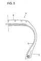
- Fig. 3 shows in cross section a right half of a passenger car tyre according to the present invention.
- the passenger car tyre 4 includes a carcass 6 as its framework, which extends between a pair of bead portions 5 in a toroidal shape.
- the crown portion of the carcass is reinforced by a belt structure 7 consisting of at least two plies, and further, a tread 8 is provided radially outwardly of the belt structure 7.
- At least one ply of belt structure 7 is formed of the composite cord described above.
- the composite cord of the present invention preferably includes 2 to 11 metallic filaments, one including 2 to 8 metallic filaments is normally suitable for use in the belt ply of a passenger car tyre.
- the end count of the composite cords i.e., the cord embedded count per unit width
- the end count of the composite cords should be increased. This leads to narrower spacing between the neighbouring composite cords, and rubber separation is likely to occur at the respective edges of the belt ply, from the ends of the cords. Such rubber separation would propagate through neighbouring composite cords, thereby causing ply separation at both edges of the belt structure.
- the rigidity of the belt structure becomes too high, which degrades riding comfort when used for a passenger car tyre.
- the end count of the composite cords within a belt ply is 10 to 50, preferably 20 to 40, per 50-mm width.
- a topping process is performed.
- the composite cord is covered with rubber at a temperature of 50°C to 120°C.
- the polymer fibre within the cord may melt, so that the rubber easily penetrates into the voids among the metallic filaments constituting the composite cord.
- At least one ply is formed of the composite cords of the present invention described above.
- the cords are disposed at an angle of 10 to 30 degrees with respect to the circumferential direction of the tyre, with the cords in one ply arranged at an opposed direction to those in the adjacent ply.
- the cord angle is set in a range between 5° and 70°.
- the composite cord of the present invention is also applicable to the carcass of a truck or bus tyre.
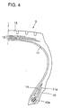
- Fig. 4 shows in cross section a right half of a pneumatic radial tyre for use on a truck or bus according to the present invention.
- the pneumatic radial tyre 9 includes a carcass 11 as its framework, which extends between a pair of bead portions 10 in a toroidal shape.
- the crown portion of the carcass is reinforced with a belt structure 12 consisting of four plies, and a tread 13 is provided radially outwardly of belt structure 12.
- a bead apex 14 is further provided between carcass 11 and its turn-up portion lla.
- a ply constituting the carcass 11 is formed of the composite cords described above.
- the composite cord of the present invention includes 2 to 11 metallic filaments
- the one including 3 to 10 metallic filaments is normally suitable for the carcass ply of a pneumatic radial tyre for use in a truck or bus.
- the end count of the composite cords in the ply needs to be adjusted. If the number of metallic filaments included in the composite cord is small, the spacing between the composite cords narrows. This may cause abrasion of the cords due to friction therebetween, or rubber separation from the turn-up portion lla of carcass 11. The rubber separation tends to propagate through neighbouring cords, thereby inducing ply separation at the end of the carcass turn-up portion.
- the end count of the composite cords per 50-mm width of the carcass ply is 10 to 55, preferably 20 to 45.
- the topping process is conducted, as in the application to the belt ply.
- the cord is covered with rubber at a temperature between 50°C and 120°C, and the polymer fibre within the cord melts, as described above. This facilitates rubber penetration into the voids among the metallic filaments constituting the composite cord.
- the carcass ply thus obtained is advantageous in that curling thereof during the subsequent process steps as well as unbinding of the metallic filaments therein is prevented.
- the carcass is formed of at least one ply, and at least one carcass ply is formed of the composite cords described above.
- the cords are disposed at an angle of 70 to 90 degrees with respect to the circumferential direction of the tyre.
- another reinforcing layer may be provided for reinforcement of the bead portion, a sidewall portion or the like.
- This reinforcing layer may also be formed of the composite cord of the present invention, or it may be formed of a steel cord, aramid fibre cord, polyester fibre cord or nylon fibre cord.
- a bead apex 14 provided between carcass 11 and its turn-up portion 11a may be formed of conventionally employed hard rubber, soft rubber or combination thereof.
- a filler may also be provided in the vicinity of an upper end of the turn-up portion of the carcass so as to restrict separation between the rubber and the metal cords embedded in the carcass ply.
- the belt structure 12 of the pneumatic radial tyre for a truck or bus of the present invention is normally formed of four plies.
- cords are disposed at an angle of 5 to 30 degrees with respect to the circumferential direction of the tyre.
- the belt ply adjoining the carcass ply has the cord angle of 40 to 70 degrees while the other three plies have the cord angle in the normal range between 5° and 30°.
- Cords that can be utilised for the belt plies include, besides the composite cord of the present invention, conventional inorganic fibre cords, such as a steel cord and a glass fibre cord, and any combination of the inorganic fibre cord with an aramid, nylon or polyester fibre cord.
- a so-called band layer may also be provided radially outwardly of the belt structure, in which the cord angle is not greater than 5° with respect to the circumferential direction of the tyre.
- the steel cord was taken out with the topped rubber attached thereto.
- the rubber was removed as much as possible from the surface of the cord. Moving a knife from the cut surface of the cord along its longitudinal direction, two neighbouring filaments out of the five or six filaments included therein were separated from the remaining portion. It was then examined whether the void that had been created between the removed filaments and the remaining portion was fully filled with rubber. For a segment of the cord of about 10 cm long, the length of the portion fully filled with rubber was measured.
- the rubber penetration is defined as a ratio of the length of the portion filled with rubber with respect to the full length of the segment (10 cm). The measurement was conducted for 10 segments for each cord, and the mean value thereof was employed as a measurement value of the cord.
- the rolling resistance was measured according to SAE J 1269.
- the measurements were represented as indices with the rolling resistance value of a conventional case being set to 100.
- the smaller index indicates the smaller rolling resistance.
- a cord employing preformed metallic filaments or a cord requiring complex twisting as in an open structure was determined as poor (x) in economical efficiency. Other cords were determined good (O) in economical efficiency.
- Comparative example 4 Example 4 Steel filament Number of steel filaments 9 9 Steel filament diameter (mm) 0.20 0.20 Cross section of steel filament Round round Polymer fibre Material - low-density PE Number of fibre - 4 Fibre structure - monofilament Composite cord Cord construction 1x9 1x9 Number of steel filaments + fibre 9 9+4 Twist pitch (mm) 20 20 Carcass Number of plies 1 1 End count per 5 cm 30 30 Belt structure Number of plies 4 4 End count per 5 cm 24 24 Steel cord construction 2+7 2+7 Steel filament diameter (mm) 0.22 0.22 Performance Rubber penetration (%) 43 95 Rust formation index in cord 100 21 Cord strength retention in Tyre after running (index) 100 100 Economical efficiency ⁇ ⁇
- Examples 1-4 of the present invention allow substantially perfect rubber penetration, and are also excellent in rust formation index, cord strength retention, rolling resistance, and economical efficiency in the manufacture of tyre.
- a composite cord is made with metallic filaments and polymer fibre twisted together.
- the polymer fibre softens or melts at the temperature condition of vulcanisation.
- the melted material of the polymer fibre as well as the rubber completely coats the metallic filaments, thereby preventing formation of voids as found in the conventional compact metal cord. Accordingly, rust formation in the composite cord is restricted, and the cord strength is retained. Economical efficiency in the tyre manufacturing process is also improved.
Landscapes
- Engineering & Computer Science (AREA)
- Mechanical Engineering (AREA)
- Textile Engineering (AREA)
- Ropes Or Cables (AREA)
- Tires In General (AREA)
- Yarns And Mechanical Finishing Of Yarns Or Ropes (AREA)
Applications Claiming Priority (2)
| Application Number | Priority Date | Filing Date | Title |
|---|---|---|---|
| JP2000023887A JP4315561B2 (ja) | 2000-02-01 | 2000-02-01 | 複合コードを用いた空気入りタイヤ |
| JP2000023887 | 2000-02-01 |
Publications (3)
| Publication Number | Publication Date |
|---|---|
| EP1123818A2 true EP1123818A2 (de) | 2001-08-16 |
| EP1123818A3 EP1123818A3 (de) | 2002-08-28 |
| EP1123818B1 EP1123818B1 (de) | 2007-01-03 |
Family
ID=18549972
Family Applications (1)
| Application Number | Title | Priority Date | Filing Date |
|---|---|---|---|
| EP01300831A Expired - Lifetime EP1123818B1 (de) | 2000-02-01 | 2001-01-31 | Verbundseil und Reifen mit demselben |
Country Status (4)
| Country | Link |
|---|---|
| US (1) | US6755226B2 (de) |
| EP (1) | EP1123818B1 (de) |
| JP (1) | JP4315561B2 (de) |
| DE (1) | DE60125609T2 (de) |
Cited By (1)
| Publication number | Priority date | Publication date | Assignee | Title |
|---|---|---|---|---|
| WO2009080077A1 (en) * | 2007-12-21 | 2009-07-02 | Pirelli Tyre S.P.A. | Tire having a reinforced bead structure |
Families Citing this family (15)
| Publication number | Priority date | Publication date | Assignee | Title |
|---|---|---|---|---|
| US6703126B1 (en) * | 1999-10-25 | 2004-03-09 | Sumitomo Rubber Industries, Ltd. | Metallic cord and pneumatic tire employing the metallic cord |
| JP2010510124A (ja) * | 2006-11-22 | 2010-04-02 | ピレリ・タイヤ・ソチエタ・ペル・アツィオーニ | 軽量ビードコアを有するタイヤ |
| US20090107609A1 (en) * | 2007-10-31 | 2009-04-30 | Walter Kevin Westgate | High Extensible Cut-Resistant Barrier |
| FR2938959B1 (fr) * | 2008-11-25 | 2010-12-24 | Airbus France | Procede de localisation d'un profile longiligne insere entre des preformes de renforts fibreux assemblees pour former une piece en materiau composite |
| US8375692B2 (en) * | 2010-07-16 | 2013-02-19 | E I Du Pont De Nemours And Company | Composite cord having a metal core and method of making |
| KR101446894B1 (ko) * | 2011-12-14 | 2014-10-07 | 한국타이어 주식회사 | 중하중용 타이어의 제조방법 |
| CN104936794B (zh) * | 2012-10-18 | 2018-01-02 | 科德沙环球纱线工业和贸易股份公司 | 用于子午线车辆轮胎的加强带束层包 |
| WO2017106495A1 (en) | 2015-12-17 | 2017-06-22 | Bridgestone Americas Tire Operations, Llc | Tire ply steel fabric having specified weft cords, rubber covered tire ply thereof, and related processes |
| DE102016207561A1 (de) * | 2016-05-03 | 2017-11-09 | Continental Reifen Deutschland Gmbh | Nutzfahrzeugreifen |
| FR3059597A1 (fr) * | 2016-12-05 | 2018-06-08 | Compagnie Generale Des Etablissements Michelin | Pneumatique comportant une armature de sommet allegee |
| JP6785152B2 (ja) * | 2016-12-27 | 2020-11-18 | 株式会社ブリヂストン | スチールコードの製造方法 |
| WO2018199122A1 (ja) | 2017-04-27 | 2018-11-01 | 株式会社ブリヂストン | エラストマー補強用コード |
| EP3702175A4 (de) | 2017-10-25 | 2021-07-14 | Bridgestone Corporation | Reifen |
| EP3730692A4 (de) * | 2017-12-22 | 2022-01-19 | Bridgestone Corporation | Elastomerverstärkungscord |
| EP3875678A4 (de) * | 2018-10-30 | 2022-08-31 | Bridgestone Corporation | Elastomerverstärkungscord |
Citations (4)
| Publication number | Priority date | Publication date | Assignee | Title |
|---|---|---|---|---|
| BE900175A (fr) * | 1984-04-28 | 1984-11-16 | Kokoku Steel Wire | Corde d'acier. |
| DE4125887A1 (de) * | 1991-08-05 | 1993-02-11 | Uniroyal Englebert Gmbh | Metallcord |
| US5279695A (en) * | 1991-09-05 | 1994-01-18 | The Goodyear Tire & Rubber Company | Process for manufacturing a cable for reinforcing rubber articles |
| EP1033435A1 (de) * | 1999-03-04 | 2000-09-06 | N.V. Bekaert S.A. | Stahlseil mit einem polymeren Kern |
Family Cites Families (5)
| Publication number | Priority date | Publication date | Assignee | Title |
|---|---|---|---|---|
| NL6919060A (de) * | 1966-02-24 | 1970-07-02 | ||
| WO1985002210A1 (en) * | 1983-11-14 | 1985-05-23 | Sumitomo Rubber Industries, Ltd. | Steel cord |
| JPS6226101A (ja) * | 1985-07-26 | 1987-02-04 | Yokohama Rubber Co Ltd:The | 高速走行用空気入りタイヤ |
| JPH0649784A (ja) * | 1992-07-24 | 1994-02-22 | Bridgestone Corp | エラストマー製品補強用複合コードおよび空気入りラジアルタイヤ |
| JP3294378B2 (ja) * | 1993-04-21 | 2002-06-24 | 住友ゴム工業株式会社 | 空気入りタイヤ |
-
2000
- 2000-02-01 JP JP2000023887A patent/JP4315561B2/ja not_active Expired - Fee Related
-
2001
- 2001-01-31 EP EP01300831A patent/EP1123818B1/de not_active Expired - Lifetime
- 2001-01-31 DE DE60125609T patent/DE60125609T2/de not_active Expired - Lifetime
- 2001-02-01 US US09/773,356 patent/US6755226B2/en not_active Expired - Fee Related
Patent Citations (4)
| Publication number | Priority date | Publication date | Assignee | Title |
|---|---|---|---|---|
| BE900175A (fr) * | 1984-04-28 | 1984-11-16 | Kokoku Steel Wire | Corde d'acier. |
| DE4125887A1 (de) * | 1991-08-05 | 1993-02-11 | Uniroyal Englebert Gmbh | Metallcord |
| US5279695A (en) * | 1991-09-05 | 1994-01-18 | The Goodyear Tire & Rubber Company | Process for manufacturing a cable for reinforcing rubber articles |
| EP1033435A1 (de) * | 1999-03-04 | 2000-09-06 | N.V. Bekaert S.A. | Stahlseil mit einem polymeren Kern |
Cited By (1)
| Publication number | Priority date | Publication date | Assignee | Title |
|---|---|---|---|---|
| WO2009080077A1 (en) * | 2007-12-21 | 2009-07-02 | Pirelli Tyre S.P.A. | Tire having a reinforced bead structure |
Also Published As
| Publication number | Publication date |
|---|---|
| EP1123818B1 (de) | 2007-01-03 |
| JP2001214387A (ja) | 2001-08-07 |
| US6755226B2 (en) | 2004-06-29 |
| JP4315561B2 (ja) | 2009-08-19 |
| US20010011569A1 (en) | 2001-08-09 |
| DE60125609T2 (de) | 2007-10-11 |
| DE60125609D1 (de) | 2007-02-15 |
| EP1123818A3 (de) | 2002-08-28 |
Similar Documents
| Publication | Publication Date | Title |
|---|---|---|
| EP1123818B1 (de) | Verbundseil und Reifen mit demselben | |
| US7316254B2 (en) | Pneumatic tire | |
| EP2219884B1 (de) | Hybridseile zur reifenverstärkung | |
| JP2001234444A (ja) | 複合コードおよびそれを用いた空気入りタイヤ | |
| US5935354A (en) | Tire having reinforcement ply with discontinuous substantially circumferential metal wires or cables | |
| US7165586B2 (en) | Pneumatic tire with blended composite fiber cords | |
| JP4205196B2 (ja) | 空気入りラジアルタイヤ | |
| JP3179915B2 (ja) | 空気入りタイヤ | |
| JP2001301430A (ja) | ビードコア及びそれを用いた空気入りタイヤ | |
| JP3759292B2 (ja) | ゴム物品補強用スチールコード及び空気入りタイヤ | |
| JP2764878B2 (ja) | 自動二輪車用ラジアルタイヤ | |
| JP2001130214A (ja) | 空気入りラジアルタイヤ | |
| US7104039B2 (en) | Metallic cord and pneumatic tire employing the metallic cord | |
| JP3509372B2 (ja) | 空気入りラジアルタイヤ | |
| JPS6127519B1 (de) | ||
| JP2000177311A (ja) | 空気入りラジアルタイヤ | |
| JP3213698B2 (ja) | スチールコード及びスチールラジアルタイヤ | |
| JP2010126074A (ja) | 乗用車用空気入りラジアルタイヤ及びその製造方法 | |
| JPH05246206A (ja) | 空気入りタイヤ | |
| JP3987207B2 (ja) | 空気入りタイヤ | |
| JPH06346386A (ja) | ゴム物品補強用金属コード | |
| EP1095793B1 (de) | Metallkord und Luftreifen mit demselben | |
| JP4443731B2 (ja) | 金属素線およびそれを用いた空気入りタイヤ | |
| JP4138296B2 (ja) | 空気入りタイヤ | |
| JPH05124403A (ja) | 空気入りラジアルタイヤ |
Legal Events
| Date | Code | Title | Description |
|---|---|---|---|
| PUAI | Public reference made under article 153(3) epc to a published international application that has entered the european phase |
Free format text: ORIGINAL CODE: 0009012 |
|
| AK | Designated contracting states |
Kind code of ref document: A2 Designated state(s): AT BE CH CY DE DK ES FI FR GB GR IE IT LI LU MC NL PT SE TR |
|
| AX | Request for extension of the european patent |
Free format text: AL;LT;LV;MK;RO;SI |
|
| PUAL | Search report despatched |
Free format text: ORIGINAL CODE: 0009013 |
|
| AK | Designated contracting states |
Kind code of ref document: A3 Designated state(s): AT BE CH CY DE DK ES FI FR GB GR IE IT LI LU MC NL PT SE TR |
|
| AX | Request for extension of the european patent |
Free format text: AL;LT;LV;MK;RO;SI |
|
| RIC1 | Information provided on ipc code assigned before grant |
Free format text: 7B 60C 9/00 A, 7D 07B 1/06 B, 7D 07B 1/16 B |
|
| 17P | Request for examination filed |
Effective date: 20021015 |
|
| AKX | Designation fees paid |
Designated state(s): DE FR GB |
|
| 17Q | First examination report despatched |
Effective date: 20050629 |
|
| GRAP | Despatch of communication of intention to grant a patent |
Free format text: ORIGINAL CODE: EPIDOSNIGR1 |
|
| GRAS | Grant fee paid |
Free format text: ORIGINAL CODE: EPIDOSNIGR3 |
|
| RIN1 | Information on inventor provided before grant (corrected) |
Inventor name: TODA, OSAMU,C/O SUMITOMO RUBBER IND., LTD. Inventor name: MIYAZAKI, SHINICHI,C/O SUMITOMO RUBBER IND., LTD. |
|
| GRAA | (expected) grant |
Free format text: ORIGINAL CODE: 0009210 |
|
| AK | Designated contracting states |
Kind code of ref document: B1 Designated state(s): DE FR GB |
|
| REG | Reference to a national code |
Ref country code: GB Ref legal event code: FG4D |
|
| REF | Corresponds to: |
Ref document number: 60125609 Country of ref document: DE Date of ref document: 20070215 Kind code of ref document: P |
|
| ET | Fr: translation filed | ||
| PLBE | No opposition filed within time limit |
Free format text: ORIGINAL CODE: 0009261 |
|
| STAA | Information on the status of an ep patent application or granted ep patent |
Free format text: STATUS: NO OPPOSITION FILED WITHIN TIME LIMIT |
|
| 26N | No opposition filed |
Effective date: 20071005 |
|
| PGFP | Annual fee paid to national office [announced via postgrant information from national office to epo] |
Ref country code: DE Payment date: 20110126 Year of fee payment: 11 |
|
| PGFP | Annual fee paid to national office [announced via postgrant information from national office to epo] |
Ref country code: GB Payment date: 20110126 Year of fee payment: 11 |
|
| PGFP | Annual fee paid to national office [announced via postgrant information from national office to epo] |
Ref country code: FR Payment date: 20120202 Year of fee payment: 12 |
|
| GBPC | Gb: european patent ceased through non-payment of renewal fee |
Effective date: 20120131 |
|
| PG25 | Lapsed in a contracting state [announced via postgrant information from national office to epo] |
Ref country code: GB Free format text: LAPSE BECAUSE OF NON-PAYMENT OF DUE FEES Effective date: 20120131 Ref country code: DE Free format text: LAPSE BECAUSE OF NON-PAYMENT OF DUE FEES Effective date: 20120801 |
|
| REG | Reference to a national code |
Ref country code: DE Ref legal event code: R119 Ref document number: 60125609 Country of ref document: DE Effective date: 20120801 |
|
| REG | Reference to a national code |
Ref country code: FR Ref legal event code: ST Effective date: 20130930 |
|
| PG25 | Lapsed in a contracting state [announced via postgrant information from national office to epo] |
Ref country code: FR Free format text: LAPSE BECAUSE OF NON-PAYMENT OF DUE FEES Effective date: 20130131 |