EP1122731B1 - Einrichtung für Plattenkassette - Google Patents
Einrichtung für Plattenkassette Download PDFInfo
- Publication number
- EP1122731B1 EP1122731B1 EP01300854A EP01300854A EP1122731B1 EP 1122731 B1 EP1122731 B1 EP 1122731B1 EP 01300854 A EP01300854 A EP 01300854A EP 01300854 A EP01300854 A EP 01300854A EP 1122731 B1 EP1122731 B1 EP 1122731B1
- Authority
- EP
- European Patent Office
- Prior art keywords
- disk
- disk cartridge
- detection
- cartridge
- positioning
- Prior art date
- Legal status (The legal status is an assumption and is not a legal conclusion. Google has not performed a legal analysis and makes no representation as to the accuracy of the status listed.)
- Expired - Lifetime
Links
- 238000001514 detection method Methods 0.000 claims abstract description 88
- 230000003287 optical effect Effects 0.000 claims description 12
- 230000002265 prevention Effects 0.000 abstract description 5
- 238000003780 insertion Methods 0.000 description 12
- 230000037431 insertion Effects 0.000 description 12
- 239000003550 marker Substances 0.000 description 2
- 238000003466 welding Methods 0.000 description 2
- 230000000881 depressing effect Effects 0.000 description 1
- 230000000994 depressogenic effect Effects 0.000 description 1
- 230000000694 effects Effects 0.000 description 1
- 230000010365 information processing Effects 0.000 description 1
- 230000001678 irradiating effect Effects 0.000 description 1
Images


Classifications
-
- G—PHYSICS
- G11—INFORMATION STORAGE
- G11B—INFORMATION STORAGE BASED ON RELATIVE MOVEMENT BETWEEN RECORD CARRIER AND TRANSDUCER
- G11B25/00—Apparatus characterised by the shape of record carrier employed but not specific to the method of recording or reproducing, e.g. dictating apparatus; Combinations of such apparatus
- G11B25/04—Apparatus characterised by the shape of record carrier employed but not specific to the method of recording or reproducing, e.g. dictating apparatus; Combinations of such apparatus using flat record carriers, e.g. disc, card
-
- G—PHYSICS
- G11—INFORMATION STORAGE
- G11B—INFORMATION STORAGE BASED ON RELATIVE MOVEMENT BETWEEN RECORD CARRIER AND TRANSDUCER
- G11B17/00—Guiding record carriers not specifically of filamentary or web form, or of supports therefor
- G11B17/02—Details
- G11B17/04—Feeding or guiding single record carrier to or from transducer unit
- G11B17/041—Feeding or guiding single record carrier to or from transducer unit specially adapted for discs contained within cartridges
- G11B17/044—Indirect insertion, i.e. with external loading means
- G11B17/046—Indirect insertion, i.e. with external loading means with pivoting loading means
-
- G—PHYSICS
- G11—INFORMATION STORAGE
- G11B—INFORMATION STORAGE BASED ON RELATIVE MOVEMENT BETWEEN RECORD CARRIER AND TRANSDUCER
- G11B19/00—Driving, starting, stopping record carriers not specifically of filamentary or web form, or of supports therefor; Control thereof; Control of operating function ; Driving both disc and head
- G11B19/20—Driving; Starting; Stopping; Control thereof
- G11B19/2009—Turntables, hubs and motors for disk drives; Mounting of motors in the drive
-
- G—PHYSICS
- G11—INFORMATION STORAGE
- G11B—INFORMATION STORAGE BASED ON RELATIVE MOVEMENT BETWEEN RECORD CARRIER AND TRANSDUCER
- G11B23/00—Record carriers not specific to the method of recording or reproducing; Accessories, e.g. containers, specially adapted for co-operation with the recording or reproducing apparatus ; Intermediate mediums; Apparatus or processes specially adapted for their manufacture
- G11B23/02—Containers; Storing means both adapted to cooperate with the recording or reproducing means
- G11B23/03—Containers for flat record carriers
- G11B23/0301—Details
- G11B23/0302—Auxiliary features
-
- G—PHYSICS
- G11—INFORMATION STORAGE
- G11B—INFORMATION STORAGE BASED ON RELATIVE MOVEMENT BETWEEN RECORD CARRIER AND TRANSDUCER
- G11B23/00—Record carriers not specific to the method of recording or reproducing; Accessories, e.g. containers, specially adapted for co-operation with the recording or reproducing apparatus ; Intermediate mediums; Apparatus or processes specially adapted for their manufacture
- G11B23/02—Containers; Storing means both adapted to cooperate with the recording or reproducing means
- G11B23/03—Containers for flat record carriers
- G11B23/0301—Details
- G11B23/0311—Wrong insertion preventing means
-
- G—PHYSICS
- G11—INFORMATION STORAGE
- G11B—INFORMATION STORAGE BASED ON RELATIVE MOVEMENT BETWEEN RECORD CARRIER AND TRANSDUCER
- G11B23/00—Record carriers not specific to the method of recording or reproducing; Accessories, e.g. containers, specially adapted for co-operation with the recording or reproducing apparatus ; Intermediate mediums; Apparatus or processes specially adapted for their manufacture
- G11B23/02—Containers; Storing means both adapted to cooperate with the recording or reproducing means
- G11B23/03—Containers for flat record carriers
- G11B23/0301—Details
- G11B23/0313—Container cases
- G11B23/0316—Constructional details, e.g. shape
Definitions
- the present invention relates to a disk cartridge apparatus capable of recording an information signal on a signal recording layer or reproducing an information signal from the signal recording layer by irradiating laser beams on the signal recording layer of an optical disk, for example. More specifically, the present invention relates to a disk cartridge apparatus of a so-called compatible type in which a plurality of disk cartridges having cartridge housings different in size and thickness for storing therein disks having different diameters are selectively loaded on a recording and reproducing apparatus and in which while the disk cartridges different in size and thickness are being loaded on the recording and reproducing apparatus, heights of respective switch detection surfaces of disk cartridges different in size are aligned with a detection switch of the recording and reproducing apparatus.
- Optical disks capable of reproducing information from a recording medium or recording information on the recording medium by optical beams have heretofore been proposed as recording mediums for a variety of information such as audio information or video information.
- This kind of optical disk can be formed of a single flat plate-like disk and hence it is easy to handle.
- it because it has a large recording capacity as compared with other recording medium such as a magnetic tape, it is widely applied as a recording medium for audio information, video information and data processed by a computer.
- a demand for more miniaturizing a recording and/or reproducing apparatus using an optical recording medium such as an optical disk is increasing because a space in which the recording and/or reproducing apparatus is assembled into an information processing apparatus such as a computer should be reduced more.
- the recording medium In order to miniaturize the recording and/or reproducing apparatus, the recording medium also should be miniaturized and a demand for a high storage capacity recording medium also is increasing.
- a plurality of kinds of disk cartridges having cartridge housings of different size and different thickness to store therein disks having different diameters as recording mediums.
- the assignee of the present application has previously proposed these disk cartridges as Japanese Patent Application No. 11-176029.
- a disk cartridge has mis-erase protection detection hole and a disk discrimination detection hole.
- These detection holes are generally discriminated by depressing a detection pin of a mode detection switch on a drive apparatus side.
- a tolerance of a height of the detection pin of the mode detection switch falls within approximately ( 0.1 mm and an accuracy of the detection pin is low as compared with surrounding parts. There is then a large possibility that these detection holes will be discriminated erroneously.
- JP-A-8-167,215 discloses a disk recording/reproducing apparatus in accordance with the pre-characterising part of claim 1. It allows the loading of more than one type of cartridge (of different sizes) and provides positioning pins for the smaller cartridges which have a top which retracts into a hollow base to avoid fouling a larger type of cartridge.
- EP-A-1017056 discloses a disk recording/reproducing apparatus which can receive disks of different capacities but having a common size and shape of cartridge housing. Constant height supports are provided on the apparatus chassis onto which the housing is pressed to assure a consistent position.
- JP-A-2000-036,147 discloses apparatus for receiving different types of cassette which has a post for height positioning of the cassette.
- the cassettes of different types have a surface for contacting the post, the surface being recessed as necessary to assure correct positioning.
- the present invention is made in order to solve the above problems and is intended to provide a disk cartridge apparatus in which respective switch detection planes of disk cartridges can be made flush with a mode detection switch of a drive apparatus when a plurality of disk cartridges which are different in size and thickness are loaded onto the drive apparatus.
- a disk recording/ reproducing apparatus for selectively receiving a first disk cartridge having at least a first detection hole and a second disk cartridge smaller than said first disk cartridge and having at least a second detection hole
- the apparatus comprising: a turn table; an optical pickup; a first positioning pin having a first height-positioning base to be engaged with a positioning aperture provided on said first cartridge for positioning it relative to the apparatus; and a second positioning pin having a second height-positioning base to be engaged with a positioning aperture provided on said second cartridge for positioning it relative to the apparatus; characterised in that the heights of the first and second height-positioning bases are different such that a height of said first detection hole when said first disk cartridge is installed and a height of said second detection hole when said second disk cartridge is installed become the same relative to the apparatus; and in that a common detection switch for detecting said first detection hole and said second detection hole is provided.
- the disk cartridges are loaded by on the recording and reproducing apparatus and have positions thereof decided on by the respective height positioning base so that the respective switch detection surfaces of the disk cartridges can be aligned with the detection switch.
- the detection holes of the disk cartridges different in size and thickness from being discriminated erroneously without changing the heights of the detection switches.
- a disk cartridge apparatus according to an embodiment of the present invention will be described with reference to the drawings, in which case the present invention is applied to two disk cartridges having large and small diameters.
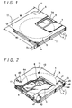
- FIG. 1 is a top perspective view illustrating a disk cartridge storing therein a disk having a large diameter ( hereinafter referred to as a "first disk cartridge”) with its shutter plate being opened.
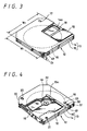
- FIG. 2 is a bottom perspective view illustrating the same disk cartridge with its shutter plate being opened.
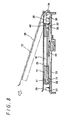
- FIG. 3 is a top perspective view illustrating a disk cartridge storing therein a disk having a small diameter (hereinafter referred to as a "second disk cartridge”) with its shutter plate being opened.
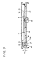
- FIG. 4 is a bottom perspective view illustrating the same disk cartridge with its shutter plate being opened.
- a first disk cartridge is generally depicted by reference numeral 1, and a cartridge housing 2 is comprised of an upper half 3 and a lower half 4 which are joined at their joint surfaces by ultrasonic welding.
- a disk 5 stored within the first disk cartridge 1 is an optical disk, for example, and an outside diameter of a disk is (64.8 mm, by way of example.
- the disk housing 2 is standardized in size such that a length W1 of one length perpendicular to the disk cartridge 1 insertion direction (shown by an arrow-like marker 6) is 72 mm, a length W2 of the other side perpendicular to the above side is 68 mm and a thickness D1 is 5 mm.
- the above first disk cartridge 1 includes a slide shutter plate 7 that can be slid to open and close both surfaces of the cartridge housing 2.
- this shutter plate 7 is opened on the upper surface side of the disk cartridge 1, the disk 5 is partly exposed at its upper surface along the diameter from an opening window 3a defined on the upper half 3.
- the shutter plate is opened on the lower surface side of the disk cartridge 1, the disk 5 is partly exposed at its lower surface (read/write surface) along the diameter from an opening window 4a of the lower half 4.
- a chucking plate 8 of the disk 5 is exposed.
- the lower half 4 of the first disk cartridge 1 has an oblong location hole 9 defined the top of the insertion side and a circular location hole 10 defined at the rear of the insertion side in the opposite direction of the location hole 9.
- the two corners of the top of the insertions side of the first disk cartridge 1 are diagonally cut so as to shape relatively large recessed surfaces 11,11.
- the second disk cartridge is generally depicted by reference numeral 12.
- a cassette housing 12 is comprised of an upper half 14 and a lower half 15 which are joined at their joint surfaces by ultrasonic welding.
- a disk 16 stored within the second disk cartridge 12 is an optical disk, for example, and its disk outside diameter is (50 mm, by way of example.
- the disk housing 13 is standardized such that a length W3 of one side perpendicular to the disk cartridge 1 insertion direction (shown by an arrow-like marker 17) is 58 mm, a length W4 of the other side perpendicular to this side is 53 mm and a thickness D2 is 4 mm.
- the above second disk cartridge 12 includes a shutter plate 18 that can be slid to open and close both surfaces of the cartridge housing 13.
- this shutter plate 18 is opened on the upper surface side of the disk cartridge 12, the disk 16 is partly exposed at its upper surface along the diametrical direction from an opening window 14a defined on the upper half 14.
- the disk 16 is partly exposed at its lower surface (recording layer) along the diametrical direction from an opening window 15a defined on the lower half 15.
- a chucking plate 19 of the disk 16 is exposed.
- the lower half 15 of the second disk cartridge 12 has an oblong location hole 20 defined at the top of the insertion side and a circular location hole 21 defined at the rear of the insertion side in the opposite direction of the location hole 20.
- the two corners of the top of the insertions side of the first disk cartridge 12 are diagonally cut so as to shape relatively large recessed surfaces 22, 22.
- FIG. 5 is a plan view of a chassis 23 of a cassette compartment (hereinafter referred to as a "cassette compartment") of a recording and reproducing apparatus onto which are loaded the above disk cartridges.
- a phantom line shows the state in which the first disk cartridge 1 is loaded onto the chassis 23.
- FIG. 6 is a cross-sectional view illustrating the state in which the first disk cartridge 1 has properly been positioned on the chassis 23.
- the first disk cartridge 1 is inserted into a holder 25 which can swing about a hinge portion 24 in an pop-up fashion (pop-up fashion) from the direction shown by an arrow. Then, when the holder 25 is swung in the chassis 23 side, the first disk cartridge is brought to the loading position.
- the chassis 23 has at its one side (right-hand side) opposite to the hinge portion 24 side formed a pair of protrusions which are used to determine the height of the first disk cartridge 1.
- the chassis 23 has a pair of protrusions 30, 31 formed adjacent to the insides of these positioning pins 28, 29 to determine the height of the second disk cartridge 12.
- On the two protrusions 30, 31 are prjectingly formed positioning pins 32, 33 with which the location holes 20, 21 of the second disk cartridge 12 are engaged.
- the chassis 23 has a pair of protrusions 34, 35 of the same height as that of the protrusions 26, 27 for determining the height of the first disk cartridge 1 at positions symmetrical to those of the pair of protrusions 26, 27 of the first disk cartridge 1.
- the chassis 23 has protrusions 36, 37 of the same height as that of the protrusions 30, 31 for determining the height of the second disk cartridge 12 at positions adjacent to the insides of the two protrusions 34, 35.
- The-protrusions 30, 31 and 36, 37 which are used to determine the height of the second disk cartridge 12 are slightly higher than the protrusions 26, 27 and 34, 35 which are used to determine the height of the first disk cartridge 1.
- the first disk cartridge 1 loaded on the above chassis 23 can be positioned properly. Simultaneously, the height of the lower surface of the first disk cartridge 1 is properly determined by the respective protrusions 26, 27, 34, 35, whereby the first disk cartridge 1 can be held in a horizontal state.
- the first disk cartridge 1 has stepped relief holes 40, 41 so that the first disk cartridge may not interfere with the pair of positioning pins 32, 33 and the protrusions 30, 31 of the second disk cartridge 12.
- the first disk cartridge has relief holes 42, 43 (see FIG. 2) so that the first disk cartridge may escape from the protrusions 36, 37 of the second disk cartridge 12.
- FIG. 7 A phantom line in FIG. 7 illustrates the state in which the second disk cartridge 12 is loaded onto the chassis 23.
- FIG. 8 is a cross-sectional view showing the state in which the second disk cartridge 12 is properly positioned on the chassis 23.
- the second disk cartridge 12 loaded on the chassis 23 can be positioned properly. Simultaneously, the height of the lower surface of the second disk cartridge 12 is properly determined by the respective protrusions 30, 31, 36, 37, whereby the second disk cartridge 12 can be held in a horizontal state.
- the second disk cartridge 12 In the state in which the second disk cartridge 12 is loaded onto the chassis 23, since the positioning pins 28, 29 and the protrusions 34, 35 for the first disk cartridge 1 are located at the positions at which they may not interfere with the second disk cartridge 12, the second disk cartridge does not need any special relief holes. If the positioning pins 32, 33 of the second disk cartridge 12 are located outside the outside diameter of the disk 5 so as not to interfere with the disk 5 when the first disk cartridge 1 is loaded on the chassis 23, then the second disk cartridge can be loaded on the chassis without bothering the first disk cartridge 1.
- the reason why the protrusion for determining the height of the second disk cartridge 12 are higher than the protrusions for determining the height of the first disk cartridge 1 is that a difference between the thickness (5 mm) of the housing 2 of the first disk cartridge 1 and the thickness (4 mm) of the housing 13 of the second disk cartridge 12 is adjusted by the heights of the protrusions such that the recording layers of the disks 5 and 16 can be accurately irradiated with spots of laser beams from the optical pickup device 39.
- the first disk cartridge 1 has on one side of its back provided a mis-erase protection plug 44 for protecting recorded information from being erased from the disk 5 by mistake.
- the mis-erase protection plug 44 can be slid from the outside of the cartridge housing 2.
- a mis-erase protection detection hole 45 defined on the lower half 4 can be closed or opened by a switch detection surface 46 which forms a part of the plug 44.
- the position of the mis-erase protection plug 44 can be discriminated by detecting whether or not a detection pin 47a of a detection switch 47 disposed on the chassis 23 is depressed by this switch detection surface 46 as shown in FIG. 9.
- a discrimination hole 48 for discriminating the specifications of the first disk cartridge 1 is provided adjacent to the above mis-erase protection detection hole 45.
- the second disk cartridge 12 has at its position near one side of the back provided a mis-erase protection plug 49 for protecting recorded information from being erased from the disk 16 by mistake.
- the mis-erase protection plug 49 can be slid from the outside of the cartridge housing 13.
- a mis-erase protection detection hole 50 defined on the lower half 15 can be closed or opened by a switch detection surface 51 which forms a part of the plug 49.
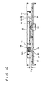
- the position of the mis-erase protection plug 49 can be discriminated by detecting whether or not a detection pin 52a of a detection switch 52 disposed on the chassis 23 is pressed by this switch detection surface 51 as shown in FIG. 10.
- a media sensor hole 53 for sensing a media type of the second disk cartridge 12 is provided adjacent to the above mis-erase protection detection hole 50.
- the height levels of the respective switch detection surfaces 46, 51 are different depending on the thickness of the disk cartridge and the thickness of the cartridge shell.
- a height H1 from the chassis 23 to the switch detection surface 46 of the first disk cartridge 1 and a height H2 from the chassis 23 to the switch detection surface 51 of the second disk cartridge 12 are set to be identical to each other.
- Diameters of and distances between the mis-erase preventing detection holes 45, 50, of the mis-erase preventing plugs 44, 49 of the first and second disk cartridges 1, 12 and the discrimination holes 48, 53 are made identical to each other.
- the disk cartridge apparatus has a merit that two kinds of disk cartridges different in size and thickness can selectively loaded thereon and recorded or reproduced.
- the heights from the chassis 23 of disk cartridges 1, 12 are set, respectively, the height H1 from the chassis 23 of the switch detection surface 46 and the height H2 from the chassis 23 of the switch detection surface 51 can be made identical to each other.
- the diameters of and the distances between the mis-erase preventing detection holes 45, 50 of the mis-erase preventing plugs 44, 49 and the discrimination holes 48, 53 can be made identical to each other.
- the same detection switch 47, 53 for the mis-erase preventing plugs 44, 49 of the first and second disk cartridges 1, 12 can be used.
- the disk cartridge apparatus can include a highly-reliable mis-erase preventing mechanism.
- One detection switche is used to provide the function of detection switches 47, 52 in common by sliding it relative to the respective switch detection holes 45, 50 of the disk cartridges 1, 12.
- the present invention is not limited thereto and there is obtained the disk cartridge apparatus in which detection switches for detecting the discrimination holes 48, 53 also can be prevented from being discriminated erroneously.
- the first disk cartridge 1 Since the first disk cartridge 1 has the relief hole so as to interfere with the positioning pins 32, 33 of the second disk cartridge 12 when the first disk cartridge 1 is loaded and the positioning pins 32, 33 of the second disk cartridge 12 are located outside the outer diameter of the disk 3 so as not to interfere with the disk 5 when the first disk cartridge 1 is loaded on the chassis 23, there can be obtained a highly-reliable disk cartridge apparatus on which two kinds of disk cartridges different in size can be loaded.
- the two disk cartridges 1, 12 have the recessed surfaces 11, 22 formed at the two corner portions in the insertion side, a user can easily recognize the insertion direction of the disk cartridge and hence the disk cartridge can be prevented from being inserted in the wrong direction. Even when a user inserts the disk cartridge into the holder 25 in the slanting direction, the recessed surfaces 11, 22 can function as guide surfaces to correct the insertion direction of the disk cartridge so that the disk cartridge can be inserted into the holder 25.
- the large first disk cartridge 1 When the large first disk cartridge 1 is inserted into the disk cartridge holder 25, since the left and right side walls of the cartridge are guided by the holder 25, the large first disk cartridge can be inserted into an accurate position without providing a special guide mechanism.
- the holder 25 should be provided with a guide mechanism.
- the guide mechanism can easily be realized by a mechanism which allows the second disk cartridge to be evacuated from the large first disk cartridge when the large first disk cartridge 1 is inserted into the holder 25.
- the present invention is not limited thereto and the pair of the positioning pins can be located at the left and right of the rear end of the disk cartridge with similar action and effects being achieved.
- the pair of the positioning pins may be circular in shape.
- the present invention is applied to the two kinds of disk cartridges different in size as described above, the present invention is not limited thereto and can be applied to more than two kinds of disk cartridges different in size by forming relief holes of positioning pins at the positions at which cartridges interfere with the positioning pins or by locating positioning pins at the positions at which the positioning pins can be evacuated from the disk.
- the disk cartridge apparatus of the present invention when a plurality of disk cartridges different in size and thickness are loaded on the recording and reproducing apparatus, since the height of the switch detection surface of the disk cartridge having the large diameter and the height of the switch detection surface of the disk cartridge having the small diameter are made identical to each other relative to the detection switch, the detection holes of the disk cartridges different in size and thickness can be prevented from being discriminated erroneously, and the degree of freedom required when the mechanism is designed can be increased. Hence, the disk cartridge apparatus can be made highly-reliable.
- the disk cartridges different in size and thickness can be recorded and reproduced without moving the recording and reproducing section relative to the disk cartridges from a mechanical standpoint.
- the detection switch Since the diameters and the intervals of a plurality of detection holes of the disk cartridge different in size and thickness are made identical to each other, it becomes possible to use the same detection switch. In addition, since the detection switch is equipped with a movement mechanism, one detection switch can be made common to a plurality of disk cartridges.
- mis-erase protection detection hole whose switch detection surface can be slid to open and close and the disk discrimination detection hole are provided, there can be obtained highly-reliable disk cartridge mis-erase protection detection function and discrimination detection function.
Landscapes
- Feeding And Guiding Record Carriers (AREA)
- Packaging For Recording Disks (AREA)
- Automatic Tape Cassette Changers (AREA)
Claims (6)
- Platten-Aufzeichnungs/Wiedergabe-Gerät zum Wahlweisen Aufnehmen einer ersten Plattenkassette (1) mit wenigstens einem ersten Detektionsloch (45) und einer zweiten Plattenkassette (1) kleiner als die erste Plattenkassette (1) und mit wenigstens einem zweiten Detektionsloch (50), wobei das Gerät aufweist:dadurch gekennzeichnet, dass die Höhen der ersten und zweiten Höhenpositionierungsbasis derart unterschiedlich sind, dass beim Installieren der ersten Plattenkassette (1) eine Höhe des ersten Detektionslochs (45) und beim Installieren der zweiten Plattenkassette (1) eine Höhe des zweiten Detektionslochs (50) relativ zum Gerät gleich werden, und dass ein gemeinsamer Detektionsschalter (47) zum Detektieren des ersten Detektionslochs (45) und des zweiten Detektionslochs (50) vorgesehen ist.einen Drehteller (38),einen optischen Aufnehmer (39),einen ersten Positionierungsstift (28, 29) mit einer ersten Höhenpositionierungsbasis (26, 27), die mit einer auf der ersten Plattenkassette (1) vorgesehenen Positionierungsöffnung (9, 10) in Eingriff zu bringen ist, um sie relativ zum Gerät zu positionieren, und einen zweiten Positionierungsstift (32, 33) mit einer zweiten Höhenpositionierungsbasis (30, 31), die mit einer auf der zweiten Kassette (1) vorgesehenen Positionierungsöffnung (40, 41) in Eingriff zu bringen ist, um sie relativ zum Gerät zu positionieren,
- Platten-Aufzeichnungs/Wiedergabe-Gerät nach Anspruch 1, wobei der zweite Positionierungsstift (32, 33) vorgesehen ist, um radial außerhalb der Peripherie einer in der ersten Plattenkassette (1) enthaltenen Platte (5) positioniert zu werden.
- Platten-Aufzeichnungs/Wiedergabe-Gerät nach Anspruch 2, wobei der zweite Positionierungsstift (32, 33) vorgesehen ist, um einwärts des ersten Positionierungsstifts (28, 29) positioniert zu werden.
- Platten-Aufzeichnungs/Wiedergabe-System, mit:einem Platten-Aufzeichnungs/Wiedergabe-Gerät nach Anspruch 1, 2 oder 3 und einer Anzahl Plattenkassetten (1) mit in Größe und Dicke unterschiedlichen Kassettengehäusen (2), um darin Platten (5, 16) mit unterschiedlichen Durchmessern zu speichern.
- Platten-Aufzeichnungs/Wiedergabe-System nach Anspruch 4, wobei die Detektionslöcher (45, 50) auf den Plattenkassetten (1) identischen Durchmesser und identische Position aufweisen.
- Platten-Aufzeichnungs/Wiedergabe-System nach Anspruch 4 oder 5, wobei die Detektionslöcher (45, 50) Falschlösch-Schutzdetektionslöcher sind, bei denen eine Schaltdetektionsfläche (46, 51) zum Öffnen und Schließen der Löcher (45, 50) verschoben werden kann.
Applications Claiming Priority (2)
| Application Number | Priority Date | Filing Date | Title |
|---|---|---|---|
| JP2000028073 | 2000-02-04 | ||
| JP2000028073A JP2001222851A (ja) | 2000-02-04 | 2000-02-04 | ディスクカートリッジ装置 |
Publications (3)
| Publication Number | Publication Date |
|---|---|
| EP1122731A2 EP1122731A2 (de) | 2001-08-08 |
| EP1122731A3 EP1122731A3 (de) | 2002-07-24 |
| EP1122731B1 true EP1122731B1 (de) | 2004-01-07 |
Family
ID=18553542
Family Applications (1)
| Application Number | Title | Priority Date | Filing Date |
|---|---|---|---|
| EP01300854A Expired - Lifetime EP1122731B1 (de) | 2000-02-04 | 2001-01-31 | Einrichtung für Plattenkassette |
Country Status (14)
| Country | Link |
|---|---|
| US (1) | US6603725B2 (de) |
| EP (1) | EP1122731B1 (de) |
| JP (1) | JP2001222851A (de) |
| KR (1) | KR100675352B1 (de) |
| CN (1) | CN1198286C (de) |
| AT (1) | ATE257619T1 (de) |
| AU (1) | AU777264B2 (de) |
| CA (1) | CA2333849A1 (de) |
| DE (1) | DE60101692T2 (de) |
| ES (1) | ES2210094T3 (de) |
| HK (1) | HK1043238B (de) |
| MY (1) | MY127164A (de) |
| SG (1) | SG101956A1 (de) |
| TW (1) | TW563095B (de) |
Families Citing this family (12)
| Publication number | Priority date | Publication date | Assignee | Title |
|---|---|---|---|---|
| JP2001143356A (ja) * | 1999-11-12 | 2001-05-25 | Sony Corp | ディスクカートリッジ装置 |
| JP2001143427A (ja) * | 1999-11-12 | 2001-05-25 | Sony Corp | ディスクカートリッジ装置 |
| US6526018B1 (en) * | 1999-12-08 | 2003-02-25 | Matsushita Electric Industrial Co., Ltd. | Disk cartridge |
| US20030048732A1 (en) * | 2001-09-13 | 2003-03-13 | Matsushita Electric Industrial Co., Ltd. | Disk drive |
| JP2003091917A (ja) * | 2001-09-18 | 2003-03-28 | Sony Corp | ディスクドライブ装置 |
| US20030193884A1 (en) * | 2002-04-16 | 2003-10-16 | Louie James K. | Optical disk storage media identification |
| US7340749B2 (en) * | 2002-12-03 | 2008-03-04 | Hewlett-Packard Development Company, L.P. | Method and apparatus to detect presence of or a size of a data cartridge |
| JP4320597B2 (ja) * | 2003-01-31 | 2009-08-26 | ソニー株式会社 | 記録媒体、記録再生装置、記録再生方法 |
| US7006319B2 (en) * | 2003-03-27 | 2006-02-28 | Hewlett-Packard Development Company, L.P. | Media-detection system and method for identifying types of data cartridges |
| US7088539B2 (en) * | 2003-11-18 | 2006-08-08 | Hewlett-Packard Development Company, L.P. | Apparatus for detecting media |
| KR100616091B1 (ko) * | 2004-10-30 | 2006-08-28 | 주식회사 케이엠씨 | 광디스크 플레이어 |
| CN1877726B (zh) * | 2005-06-10 | 2010-05-05 | 鸿富锦精密工业(深圳)有限公司 | 信息记录/再现装置 |
Family Cites Families (9)
| Publication number | Priority date | Publication date | Assignee | Title |
|---|---|---|---|---|
| JP2974868B2 (ja) * | 1993-03-19 | 1999-11-10 | シャープ株式会社 | ディスク駆動装置およびディスク装置 |
| EP1146518B1 (de) * | 1993-03-23 | 2002-12-11 | Matsushita Electric Industrial Co., Ltd. | Kombination eines Kassettenadapters und einer darin unterzubringenden Kassette |
| US5548571A (en) * | 1994-10-03 | 1996-08-20 | Eastman Kodak Company | Method and apparatus for identifying data storage disks |
| JP3440596B2 (ja) * | 1994-12-12 | 2003-08-25 | ソニー株式会社 | ディスク再生装置 |
| JP3696675B2 (ja) * | 1995-12-15 | 2005-09-21 | 富士通株式会社 | 光ディスク装置 |
| KR100452081B1 (ko) * | 1996-06-05 | 2004-11-16 | 소니 가부시끼 가이샤 | 디스크 카트리지의 로딩 장치 |
| ID23810A (id) * | 1997-04-04 | 2000-05-11 | Sony Corp | Selongsong piringan |
| US6301215B1 (en) * | 1998-07-03 | 2001-10-09 | Alpine Electronics, Inc. | Recording medium driving apparatus |
| JP3205317B2 (ja) * | 1999-07-19 | 2001-09-04 | 株式会社日立製作所 | 記録再生装置 |
-
2000
- 2000-02-04 JP JP2000028073A patent/JP2001222851A/ja active Pending
-
2001
- 2001-01-22 KR KR1020010003518A patent/KR100675352B1/ko not_active IP Right Cessation
- 2001-01-29 AU AU16689/01A patent/AU777264B2/en not_active Ceased
- 2001-01-31 DE DE60101692T patent/DE60101692T2/de not_active Expired - Fee Related
- 2001-01-31 TW TW090101933A patent/TW563095B/zh not_active IP Right Cessation
- 2001-01-31 AT AT01300854T patent/ATE257619T1/de not_active IP Right Cessation
- 2001-01-31 ES ES01300854T patent/ES2210094T3/es not_active Expired - Lifetime
- 2001-01-31 EP EP01300854A patent/EP1122731B1/de not_active Expired - Lifetime
- 2001-01-31 MY MYPI20010437A patent/MY127164A/en unknown
- 2001-02-01 CA CA002333849A patent/CA2333849A1/en not_active Abandoned
- 2001-02-02 SG SG200100632A patent/SG101956A1/en unknown
- 2001-02-02 CN CNB011119721A patent/CN1198286C/zh not_active Expired - Fee Related
- 2001-02-05 US US09/777,111 patent/US6603725B2/en not_active Expired - Fee Related
-
2002
- 2002-04-16 HK HK02102875.4A patent/HK1043238B/zh not_active IP Right Cessation
Also Published As
| Publication number | Publication date |
|---|---|
| SG101956A1 (en) | 2004-02-27 |
| ATE257619T1 (de) | 2004-01-15 |
| HK1043238B (zh) | 2005-11-11 |
| JP2001222851A (ja) | 2001-08-17 |
| CN1198286C (zh) | 2005-04-20 |
| HK1043238A1 (en) | 2002-09-06 |
| AU1668901A (en) | 2001-08-09 |
| US20010021158A1 (en) | 2001-09-13 |
| EP1122731A2 (de) | 2001-08-08 |
| KR100675352B1 (ko) | 2007-01-29 |
| KR20010078046A (ko) | 2001-08-20 |
| US6603725B2 (en) | 2003-08-05 |
| MY127164A (en) | 2006-11-30 |
| DE60101692D1 (de) | 2004-02-12 |
| CN1318838A (zh) | 2001-10-24 |
| DE60101692T2 (de) | 2004-10-21 |
| CA2333849A1 (en) | 2001-08-04 |
| ES2210094T3 (es) | 2004-07-01 |
| EP1122731A3 (de) | 2002-07-24 |
| TW563095B (en) | 2003-11-21 |
| AU777264B2 (en) | 2004-10-07 |
Similar Documents
| Publication | Publication Date | Title |
|---|---|---|
| JP3178005B2 (ja) | ディスクカートリッジ | |
| EP0472443B1 (de) | Plattenkassette mit einem Verschluss | |
| EP0376570B2 (de) | Datenspeicherkassette mit einer Schreib-Schutz-Anordnung | |
| US6239950B1 (en) | High density flexible disk drive having a large capacity detecting switch provided at a position corresponding to a large capacity identifier hole provided in a case of a large capacity flexible disk | |
| US6215760B1 (en) | Method and apparatus for using a disk cartridge with pull-out type case | |
| EP1122731B1 (de) | Einrichtung für Plattenkassette | |
| US5991260A (en) | Disk cartridge and disk device using the same | |
| US6741537B1 (en) | Disk cartridge device operative with disk cartridges of different sizes and height | |
| EP1152418A1 (de) | Plattenkassetten-vorrichtung und plattenkassette | |
| US6175471B1 (en) | Disc cartridge having configuration to prevent insertion into certain disk drives | |
| KR20010087206A (ko) | 디스크 카트리지장치와 디스크 카트리지 | |
| JP2002056601A (ja) | ディスクカートリッジ装置及びディスクカートリッジ | |
| JPH11120733A (ja) | ディスクカートリッジおよびディスクドライブ装置 | |
| JP3257557B2 (ja) | 記録及び/又は再生装置 | |
| JPH10199203A (ja) | ディスクカートリッジ及び記録及び/又は再生装置 | |
| JPH103774A (ja) | ディスクカートリッジ | |
| JPH09270185A (ja) | ディスクカートリッジ | |
| KR20050067078A (ko) | 기록 매체의 카트리지 | |
| JP2000036182A (ja) | ディスクカートリッジ | |
| JP2004118895A (ja) | カートリッジ | |
| JPH09270184A (ja) | ディスクカートリッジ | |
| JPH11120734A (ja) | ディスクカートリッジおよびディスクドライブ装置 |
Legal Events
| Date | Code | Title | Description |
|---|---|---|---|
| PUAI | Public reference made under article 153(3) epc to a published international application that has entered the european phase |
Free format text: ORIGINAL CODE: 0009012 |
|
| AK | Designated contracting states |
Kind code of ref document: A2 Designated state(s): AT BE CH CY DE DK ES FI FR GB GR IE IT LI LU MC NL PT SE TR |
|
| AX | Request for extension of the european patent |
Free format text: AL;LT;LV;MK;RO;SI |
|
| PUAL | Search report despatched |
Free format text: ORIGINAL CODE: 0009013 |
|
| AK | Designated contracting states |
Kind code of ref document: A3 Designated state(s): AT BE CH CY DE DK ES FI FR GB GR IE IT LI LU MC NL PT SE TR |
|
| AX | Request for extension of the european patent |
Free format text: AL;LT;LV;MK;RO;SI |
|
| 17P | Request for examination filed |
Effective date: 20020906 |
|
| AKX | Designation fees paid |
Designated state(s): AT BE CH CY DE DK ES FI FR GB GR IE IT LI LU MC NL PT SE TR |
|
| 17Q | First examination report despatched |
Effective date: 20030327 |
|
| GRAP | Despatch of communication of intention to grant a patent |
Free format text: ORIGINAL CODE: EPIDOSNIGR1 |
|
| GRAS | Grant fee paid |
Free format text: ORIGINAL CODE: EPIDOSNIGR3 |
|
| GRAA | (expected) grant |
Free format text: ORIGINAL CODE: 0009210 |
|
| AK | Designated contracting states |
Kind code of ref document: B1 Designated state(s): AT BE CH CY DE DK ES FI FR GB GR IE IT LI LU MC NL PT SE TR |
|
| PG25 | Lapsed in a contracting state [announced via postgrant information from national office to epo] |
Ref country code: FI Free format text: LAPSE BECAUSE OF FAILURE TO SUBMIT A TRANSLATION OF THE DESCRIPTION OR TO PAY THE FEE WITHIN THE PRESCRIBED TIME-LIMIT Effective date: 20040107 Ref country code: CY Free format text: LAPSE BECAUSE OF FAILURE TO SUBMIT A TRANSLATION OF THE DESCRIPTION OR TO PAY THE FEE WITHIN THE PRESCRIBED TIME-LIMIT Effective date: 20040107 Ref country code: CH Free format text: LAPSE BECAUSE OF FAILURE TO SUBMIT A TRANSLATION OF THE DESCRIPTION OR TO PAY THE FEE WITHIN THE PRESCRIBED TIME-LIMIT Effective date: 20040107 Ref country code: BE Free format text: LAPSE BECAUSE OF FAILURE TO SUBMIT A TRANSLATION OF THE DESCRIPTION OR TO PAY THE FEE WITHIN THE PRESCRIBED TIME-LIMIT Effective date: 20040107 Ref country code: LI Free format text: LAPSE BECAUSE OF FAILURE TO SUBMIT A TRANSLATION OF THE DESCRIPTION OR TO PAY THE FEE WITHIN THE PRESCRIBED TIME-LIMIT Effective date: 20040107 Ref country code: TR Free format text: LAPSE BECAUSE OF FAILURE TO SUBMIT A TRANSLATION OF THE DESCRIPTION OR TO PAY THE FEE WITHIN THE PRESCRIBED TIME-LIMIT Effective date: 20040107 |
|
| REG | Reference to a national code |
Ref country code: GB Ref legal event code: FG4D |
|
| REG | Reference to a national code |
Ref country code: CH Ref legal event code: EP |
|
| PGFP | Annual fee paid to national office [announced via postgrant information from national office to epo] |
Ref country code: MC Payment date: 20040128 Year of fee payment: 4 Ref country code: SE Payment date: 20040128 Year of fee payment: 4 |
|
| PGFP | Annual fee paid to national office [announced via postgrant information from national office to epo] |
Ref country code: GR Payment date: 20040129 Year of fee payment: 4 Ref country code: LU Payment date: 20040129 Year of fee payment: 4 |
|
| PG25 | Lapsed in a contracting state [announced via postgrant information from national office to epo] |
Ref country code: IE Free format text: LAPSE BECAUSE OF NON-PAYMENT OF DUE FEES Effective date: 20040202 |
|
| PGFP | Annual fee paid to national office [announced via postgrant information from national office to epo] |
Ref country code: DK Payment date: 20040202 Year of fee payment: 4 |
|
| REG | Reference to a national code |
Ref country code: IE Ref legal event code: FG4D |
|
| REF | Corresponds to: |
Ref document number: 60101692 Country of ref document: DE Date of ref document: 20040212 Kind code of ref document: P |
|
| PG25 | Lapsed in a contracting state [announced via postgrant information from national office to epo] |
Ref country code: GR Free format text: LAPSE BECAUSE OF FAILURE TO SUBMIT A TRANSLATION OF THE DESCRIPTION OR TO PAY THE FEE WITHIN THE PRESCRIBED TIME-LIMIT Effective date: 20040407 Ref country code: DK Free format text: LAPSE BECAUSE OF FAILURE TO SUBMIT A TRANSLATION OF THE DESCRIPTION OR TO PAY THE FEE WITHIN THE PRESCRIBED TIME-LIMIT Effective date: 20040407 Ref country code: SE Free format text: LAPSE BECAUSE OF FAILURE TO SUBMIT A TRANSLATION OF THE DESCRIPTION OR TO PAY THE FEE WITHIN THE PRESCRIBED TIME-LIMIT Effective date: 20040407 |
|
| REG | Reference to a national code |
Ref country code: ES Ref legal event code: FG2A Ref document number: 2210094 Country of ref document: ES Kind code of ref document: T3 |
|
| REG | Reference to a national code |
Ref country code: CH Ref legal event code: PL |
|
| ET | Fr: translation filed | ||
| PLBE | No opposition filed within time limit |
Free format text: ORIGINAL CODE: 0009261 |
|
| STAA | Information on the status of an ep patent application or granted ep patent |
Free format text: STATUS: NO OPPOSITION FILED WITHIN TIME LIMIT |
|
| REG | Reference to a national code |
Ref country code: IE Ref legal event code: MM4A |
|
| 26N | No opposition filed |
Effective date: 20041008 |
|
| PG25 | Lapsed in a contracting state [announced via postgrant information from national office to epo] |
Ref country code: LU Free format text: LAPSE BECAUSE OF NON-PAYMENT OF DUE FEES Effective date: 20050131 Ref country code: MC Free format text: LAPSE BECAUSE OF NON-PAYMENT OF DUE FEES Effective date: 20050131 |
|
| PG25 | Lapsed in a contracting state [announced via postgrant information from national office to epo] |
Ref country code: PT Free format text: LAPSE BECAUSE OF NON-PAYMENT OF DUE FEES Effective date: 20040607 |
|
| PGFP | Annual fee paid to national office [announced via postgrant information from national office to epo] |
Ref country code: AT Payment date: 20090113 Year of fee payment: 9 Ref country code: ES Payment date: 20090218 Year of fee payment: 9 |
|
| PGFP | Annual fee paid to national office [announced via postgrant information from national office to epo] |
Ref country code: DE Payment date: 20090129 Year of fee payment: 9 Ref country code: NL Payment date: 20090104 Year of fee payment: 9 |
|
| PGFP | Annual fee paid to national office [announced via postgrant information from national office to epo] |
Ref country code: GB Payment date: 20090128 Year of fee payment: 9 |
|
| PGFP | Annual fee paid to national office [announced via postgrant information from national office to epo] |
Ref country code: IT Payment date: 20090130 Year of fee payment: 9 |
|
| PGFP | Annual fee paid to national office [announced via postgrant information from national office to epo] |
Ref country code: FR Payment date: 20090113 Year of fee payment: 9 |
|
| REG | Reference to a national code |
Ref country code: NL Ref legal event code: V1 Effective date: 20100801 |
|
| GBPC | Gb: european patent ceased through non-payment of renewal fee |
Effective date: 20100131 |
|
| REG | Reference to a national code |
Ref country code: FR Ref legal event code: ST Effective date: 20100930 |
|
| PG25 | Lapsed in a contracting state [announced via postgrant information from national office to epo] |
Ref country code: FR Free format text: LAPSE BECAUSE OF NON-PAYMENT OF DUE FEES Effective date: 20100201 Ref country code: NL Free format text: LAPSE BECAUSE OF NON-PAYMENT OF DUE FEES Effective date: 20100801 |
|
| PG25 | Lapsed in a contracting state [announced via postgrant information from national office to epo] |
Ref country code: AT Free format text: LAPSE BECAUSE OF NON-PAYMENT OF DUE FEES Effective date: 20100131 Ref country code: DE Free format text: LAPSE BECAUSE OF NON-PAYMENT OF DUE FEES Effective date: 20100803 |
|
| PG25 | Lapsed in a contracting state [announced via postgrant information from national office to epo] |
Ref country code: GB Free format text: LAPSE BECAUSE OF NON-PAYMENT OF DUE FEES Effective date: 20100131 |
|
| PG25 | Lapsed in a contracting state [announced via postgrant information from national office to epo] |
Ref country code: IT Free format text: LAPSE BECAUSE OF NON-PAYMENT OF DUE FEES Effective date: 20100131 |
|
| REG | Reference to a national code |
Ref country code: ES Ref legal event code: FD2A Effective date: 20110407 |
|
| PG25 | Lapsed in a contracting state [announced via postgrant information from national office to epo] |
Ref country code: ES Free format text: LAPSE BECAUSE OF NON-PAYMENT OF DUE FEES Effective date: 20110328 |
|
| PG25 | Lapsed in a contracting state [announced via postgrant information from national office to epo] |
Ref country code: ES Free format text: LAPSE BECAUSE OF NON-PAYMENT OF DUE FEES Effective date: 20100201 |