EP1122138A2 - Vorrichtung und Verfahren zur Reinigung von Scheiben eines Kraftfahrzeuges - Google Patents
Vorrichtung und Verfahren zur Reinigung von Scheiben eines Kraftfahrzeuges Download PDFInfo
- Publication number
- EP1122138A2 EP1122138A2 EP01102079A EP01102079A EP1122138A2 EP 1122138 A2 EP1122138 A2 EP 1122138A2 EP 01102079 A EP01102079 A EP 01102079A EP 01102079 A EP01102079 A EP 01102079A EP 1122138 A2 EP1122138 A2 EP 1122138A2
- Authority
- EP
- European Patent Office
- Prior art keywords
- nozzle
- cleaning
- support element
- disc
- housing
- Prior art date
- Legal status (The legal status is an assumption and is not a legal conclusion. Google has not performed a legal analysis and makes no representation as to the accuracy of the status listed.)
- Granted
Links
- 238000004140 cleaning Methods 0.000 title claims abstract description 76
- 238000000034 method Methods 0.000 title claims abstract description 12
- 238000005507 spraying Methods 0.000 claims abstract description 6
- 230000001154 acute effect Effects 0.000 claims description 3
- 230000002265 prevention Effects 0.000 claims 1
- 230000001419 dependent effect Effects 0.000 abstract 1
- 238000010586 diagram Methods 0.000 description 4
- 239000007921 spray Substances 0.000 description 4
- 230000003749 cleanliness Effects 0.000 description 1
- 230000003111 delayed effect Effects 0.000 description 1
- 239000012530 fluid Substances 0.000 description 1
- 239000007788 liquid Substances 0.000 description 1
- 238000007789 sealing Methods 0.000 description 1
- 238000005406 washing Methods 0.000 description 1
Images


Classifications
-
- B—PERFORMING OPERATIONS; TRANSPORTING
- B60—VEHICLES IN GENERAL
- B60S—SERVICING, CLEANING, REPAIRING, SUPPORTING, LIFTING, OR MANOEUVRING OF VEHICLES, NOT OTHERWISE PROVIDED FOR
- B60S1/00—Cleaning of vehicles
- B60S1/02—Cleaning windscreens, windows or optical devices
- B60S1/46—Cleaning windscreens, windows or optical devices using liquid; Windscreen washers
- B60S1/48—Liquid supply therefor
- B60S1/52—Arrangement of nozzles; Liquid spreading means
- B60S1/522—Arrangement of nozzles; Liquid spreading means moving liquid spreading means, e.g. arranged in wiper arms
-
- B—PERFORMING OPERATIONS; TRANSPORTING
- B60—VEHICLES IN GENERAL
- B60S—SERVICING, CLEANING, REPAIRING, SUPPORTING, LIFTING, OR MANOEUVRING OF VEHICLES, NOT OTHERWISE PROVIDED FOR
- B60S1/00—Cleaning of vehicles
- B60S1/02—Cleaning windscreens, windows or optical devices
- B60S1/56—Cleaning windscreens, windows or optical devices specially adapted for cleaning other parts or devices than front windows or windscreens
- B60S1/60—Cleaning windscreens, windows or optical devices specially adapted for cleaning other parts or devices than front windows or windscreens for signalling devices, e.g. reflectors
- B60S1/603—Cleaning windscreens, windows or optical devices specially adapted for cleaning other parts or devices than front windows or windscreens for signalling devices, e.g. reflectors the operation of at least a part of the cleaning means being controlled by electric means
Definitions
- the invention relates to a device for cleaning windows of a motor vehicle, especially for headlights, with a nozzle for spraying a Cleaning medium on the disc, the nozzle on a support element an actuating device is held movably at a distance from the disk Spraying parts of the pane.
- DE 44 26 051 A1 describes a device for cleaning windows Motor vehicle known, in which provided with at least one nozzle Swivel arm is provided, which is essentially at a constant distance is pivoted to the pane to be cleaned. Because of the nozzles can sweep over the surface of the pane at a constant distance consistently good cleaning results can be achieved.
- the device is that no measures are provided to only predetermined areas of the pane surface with a cleaning medium to act upon.
- DE 196 30 421 C1 describes a device for cleaning windows a motor vehicle known in which a nozzle at one end of a rod-shaped Supporting element is held. The nozzle or the support element moved translationally from a starting position into a cleaning position, wherein the disc in the cleaning position with a cleaning medium is applied. This known device also sees no measures in order to cover only parts of the pane with cleaning medium act upon.
- WO 98/21076 A1 describes a device for cleaning windows Motor vehicle known, one provided with at least one nozzle Supporting element is pivotally mounted. The support element is essentially moved at a constant distance from the disc, the nozzles each Can apply parts of the pane with cleaning medium.
- a disadvantage of the known device is that with large-area panes several nozzles must be provided. Furthermore, there are no measures specified that only allow cleaning of parts of the pane.
- the object of the present invention is therefore a device for cleaning to develop windows of a motor vehicle such that, on the one hand the consumption of cleaning medium can be reduced and secondly reliable cleaning of the pane is guaranteed.
- the device according to the invention is connected to achieve this object characterized by the preamble of claim 1, that the nozzle relative to a housing of the actuating device carrying the support element is arranged such that it can move depending on the position the support element sequentially several essentially from each other delimited sections of the disc with the part to be sprayed out of the nozzle Cleaning medium can be applied.
- the particular advantage of the device according to the invention is that achieved a significant reduction in the consumption of cleaning medium becomes.
- Characterized in that the nozzle relative to the housing carrying the support element is so movably arranged that in cooperation with the movement or the position of the support element selected areas of the Controlled disc and be charged with the cleaning medium cleaning can be restricted to such partial areas of the pane remain that are dirty. This is an optional cleaning of Partial areas of the disc allows.
- the support element performs a translatory movement and the nozzle rotates Direction out.
- the movements of the support element on the one hand and the The nozzle, on the other hand, are matched to one another so that they have different sizes Partial areas of the pane are captured by the cleaning medium.
- Advantageous can be used to select large areas, such as segments a pane associated with a high beam or low beam function are, or small sub-areas that cover sensors such as Dirt or distance sensors are used, partially cleaned.
- the nozzle can be pivoted about one arranged by the support element executed linear travel.
- a small stroke movement of the support element is advantageously sufficient to in In connection with the twisting of the nozzle, grasp all sections of the disc to be able to.
- the support element is in a Starting position in a lower corner area of the pane.
- the support element is under a pointed Angle with respect to a horizontal and / or vertical, preferably in an angular range of 15 - 40 degrees, along a straight path with adjustable bearings so that the lower one can be moved after a short travel small areas of the disc can be acted upon.
- smaller lower sensors usually covering sensors Parts of the pane cleaned.
- Another object of the invention is a method for cleaning windows specify a motor vehicle using the lowest possible Amount of cleaning medium quickly and reliably specified areas the window cleans.
- the method according to the invention is connected to achieve this object characterized by the preamble of claim 10 in that the support element is straight and the nozzle is rotated into one predetermined cleaning position can be moved, the nozzle already in front reaching the cleaning position in the desired relative position to the Disk is moved and that after reaching the cleaning position a pump is activated so that a predetermined portion of the disc with the cleaning medium.
- the particular advantage of the method according to the invention is that by the linear movement of a support element on the support element attached nozzle quickly brought into a predetermined cleaning position in which they can move through one or more sub-areas the disc can act on cleaning medium.
- a predetermined cleaning position in which they can move through one or more sub-areas the disc can act on cleaning medium.
- the disc can act on cleaning medium.
- a control program is provided in a control unit controlling the actuating unit, so that on the one hand different sub-areas are made possible approached and cleaned a pane in a desired order are and sequentially acted upon two identical disks become. For example, it can cover two headlights be cleaned sequentially, each with the maximum spray pressure for the cleaning medium is available.
- FIG. 1 schematically shows a headlight cleaning system for a motor vehicle shown as a device for cleaning windows, which essentially from an actuator 1 for a nozzle 2, a control unit 3, one Pump 4 and a reservoir serving as a reservoir for a cleaning medium 5 6 exists.
- the cleaning medium 5 is preferably a washing liquid formed via a branched supply line 7 by means of the pump 4 to the actuating devices 1, 1 ', 1 "assigned to a respective headlight is eligible.
- the actuating devices 1 ', 1 each have a rectilinearly movable adjusting piston 8 as a supporting element for the nozzle 2.
- the nozzle 2 is preferably on a free end of the actuating piston 8 positioned and rotatable about the longitudinal axis of the control piston 8 or a travel path carried out by the latter stored.
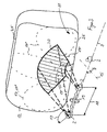
- the Nozzle 2 in a starting position 10 of the actuating piston 8 in a lower corner area 11 of a headlight cover plate 12.
- a housing 13 of the actuating device 1 is positioned such that the setting piston 8 is at an acute angle ⁇ can be extended with respect to a horizontal H.
- the angular range is preferably between 10 and 40 degrees, preferably 20 degrees.
- the actuating piston 8 When the actuating piston 8 is moved into a predetermined cleaning position 14 it has a movement component both in the direction and transversely a vehicle longitudinal axis 15.
- the resulting motion component includes an acute angle ⁇ with the vehicle longitudinal axis 15, preferably in a range between 50 and 80 degrees.
- the size of the angle is ⁇ depending on the size of the disc 12 and must not be chosen too small, otherwise the distance to the disk 12 becomes too large.
- the cleaning process of the disk 12 can only begin as soon as the actuating piston 8 by means of a motor 16 in which is controlled by the control unit 3 a position has been moved in which the nozzle 2 in front of the cover plate 12 arranged and a portion 17 of the same by spraying the cleaning medium 5 can act.
- a work area 18 now begins the nozzle 2 by the combined movement of the adjusting piston 8 in the direction of the arrow and according to the rotation of the nozzle 2 with respect to the actuating piston 8 Direction of arrow 19 is marked.
- the subareas 17 correspond to certain functions the headlight, for example lighting functions such as low beam or high beam, or sensors, such as dirt or distance sensors.
- the nozzle 2 is preferably rigidly connected to the actuating piston 8.
- the nozzle 2 also be articulated to the actuating piston 8. However, this would be a constructively more effort.
- control program By designing the control program, sequential cleaning can be carried out in a targeted manner the partial areas 17 of the disk 12 can be guaranteed. It can be taken into account that the requirements for the cleanliness of the sub-areas 17 are higher for certain functions. By repeated, in short or large time intervals can be applied to such partial areas 17 economical use of cleaning medium 5 a function enabling Condition is maintained.
- FIG. 5 shows a time line diagram from which it can be seen how the motor 16 for the control piston 8 and a motor 21 for the nozzle 2 by the control unit 3 can be controlled.
- the starting position 10 of the actuating piston 8 causes a in the housing 13 integrated locking element 22 that when activated Pump 4 the cleaning medium 5 is prevented from passing to the nozzle 2.
- the locking element 22 can be designed as a sealing ring be the end of the adjusting piston 8 facing away from the nozzle 2 is arranged and the feed in the starting position 10 of the actuating piston 8 in the housing 13 blocked.
- the motor 16 of the actuating piston 8 is actuated according to a control program on the one hand and the motor 21 of the nozzle 2 is delayed, on the other hand, so that the cleaning position 14' is reached at a time t 1 .
- the pump 4 is actuated, so that cleaning medium 5 can be applied to a predetermined partial region 17 of the disk 12.
- the pump 4 is switched off and the motors 16 and 21 are actuated in the opposite direction until the nozzle 2 or the actuating piston 8 has been moved back to the starting position 10.
- the partial areas 17 to be cleaned are moved to sequentially, the starting position 10 taking up between the cleaning operations of the actuating pistons 8.
- a plurality of partial areas 17 can also be acted upon one after the other in the working area 18 while the nozzle 2 or the actuating piston 8 is moving.
- the motors 16 and 21 are actuated one after the other until a predetermined cleaning position 14 "is assumed until the time t 1.
- This cleaning position 14" is characterized in that on the one hand the pump 4 is switched on and on the other hand the motors 16 and 21 is actuated further so that the actuating piston 8 is extended further. In this way, a larger partial area 17 can be detected.
- both the actuating piston 8 and the nozzle 2 continue to move until a further cleaning position 14 '''is reached at time t 3 , in which a further partial area 17 is acted upon.
- this cleaning position 14 ''' the nozzle continues to rotate, so that the portion 17 to be cleaned is expanded substantially in the vertical direction.
- the nozzle 2 and the actuating piston 8 are moved back into their original starting position 10.
- the housing 13 expediently has a leakage protection valve 23, so that the cleaning medium 5 escapes when the pump 4 is not actuated is prevented.
- the leakage protection valve 23 can be designed as a pressure switching valve his. If the reservoir 6 below the housing 13 of the actuator 1 is arranged, this leakage protection valve 23 can be omitted.
- the motors 16, 21 are connected to the control unit 3 by means of control lines 24.
- the control unit 3 has a control program, by means of which the Actuators 1 ', 1 "can be controlled one after the other simultaneous control of two motors 16, 21 of an actuating device 1 ' or 1 "can be done quickly while minimizing cleaning fluid consumption 5 a reliable cleaning of predetermined partial areas 17 is carried out.
- the rotational movement of the nozzle 2 can also be on opposite ones Edge 25 of the disc 12 may be aligned. This can be useful for an asymmetrical contour of the headlamp or in the case of an edge the cover plate 12 parallel adjustment of the actuating piston 8th
Landscapes
- Engineering & Computer Science (AREA)
- Mechanical Engineering (AREA)
- Water Supply & Treatment (AREA)
- Nozzles (AREA)
- Lighting Device Outwards From Vehicle And Optical Signal (AREA)
- Vehicle Cleaning, Maintenance, Repair, Refitting, And Outriggers (AREA)
Abstract
Description
- Figur 1
- ein Blockschaltbild einer erfindungsgemäßen Vorrichtung,
- Figur 2
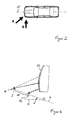
- eine Draufsicht auf ein Kraftfahrzeug,
- Figur 3
- eine perspektivische Ansicht eines vorderen linken Scheinwerfers gemäß Figur 2 in Richtung A gesehen,
- Figur 4
- eine schematische Seitenansicht des Scheinwerfers gemäß Figur 2 in Richtung Pfeil B nach Figur 2,
- Figur 5
- ein Zeitliniendiagramm entsprechend einem Steuerprogramm nach einer ersten Variante und
- Figur 6
- ein Zeitliniendiagramm entsprechend einem Steuerprogramm nach einer zweiten Variante.
Claims (11)
- Vorrichtung zur Reinigung von Scheiben eines Kraftfahrzeuges, insbesondere für Scheinwerfer, mit einer Düse zum Sprühen eines Reinigungsmediums auf die Scheibe, wobei die Düse an einem Tragelement einer Stelleinrichtung im Abstand zu der Scheibe bewegbar gehalten ist zum Besprühen von Teilbereichen der Scheibe, dadurch gekennzeichnet, dass die Düse (2) relativ zu einem das Tragelement (8) tragenden Gehäuse (13) der Stelleinrichtung (1, 1', 1") derart beweglich angeordnet ist, dass in Abhängigkeit von der Position des Tragelementes (8) sequentiell mehrere im Wesentlichen voneinander abgegrenzte Teilbereiche (17, 17', 17") der Scheibe (12) mit dem aus der Düse (2) zu sprühenden Reinigungsmedium (5) beaufschlagbar sind.
- Vorrichtung nach Anspruch 1, dadurch gekennzeichnet, dass das Tragelement (8) translatorisch bewegbar und die Düse (2) rotatorisch bewegbar angeordnet sind und dass die Bewegung des Tragelementes (8) und der Düse (2) derart aufeinander abgestimmt sind, dass die Düse (2) in einem Arbeitsbereich (18) unterschiedlich große Teilbereiche (17, 17', 17") der Scheibe (12) erfasst.
- Vorrichtung nach Anspruch 1 oder 2, dadurch gekennzeichnet, dass das Tragelement (8) aus einer Ausgangsposition (10) unterhalb der Scheibe (12) entlang eines Verfahrweges (9) unter Bildung eines spitzen Winkels (α) bezüglich einer Horizontalen (H) in eine Mehrzahl von Reinigungspositionen (14) verfahrbar ausgebildet ist, wobei sich der Abstand der Düse (2) zu der Scheibe (12) vergrößert.
- Vorrichtung nach einem der Ansprüche 1 bis 3, dadurch gekennzeichnet, dass sich die Ausgangsposition (10) des Tragelementes (8) in einem Eckbereich (11) der Scheibe (12) und eine Endposition desselben im Wesentlichen unterhalb einer Längsmittelebene der Scheibe (12) befindet.
- Vorrichtung nach einem der Ansprüche 1 bis 4, dadurch gekennzeichnet, dass die Düse (2) quer zu zwei gegenüberliegenden parallelen Randkanten (25) der Scheibe (12) derart verdrehbar angeordnet ist, dass oval- oder kreisförmige Teilbereiche (17) zwischen denselben Randkanten (25) erfasst werden.
- Vorrichtung nach einem der Ansprüche 1 bis 5, dadurch gekennzeichnet, dass die Düse (2) quer zu dem Verfahrweg (9) des Tragelementes (8) verdrehbar angeordnet ist, wobei in einer Verdrehrichtung der Düse (2) die von der Düse (2) erfassten Teilbereiche (17, 17', 17") in ihrer Fläche ansteigend ausgebildet sind.
- Vorrichtung nach einem der Ansprüche 1 bis 6, dadurch gekennzeichnet, dass das Tragelement (8) als Stellkolben ausgebildet ist, der in einem Gehäuse (13) verschieblich gelagert ist, dass in der Ausgangsposition (10) des Stellkolbens (8) ein Verriegelungselement (22) selbsttätig aktivierbar ist, derart, dass der Zufluss des Reinigungsmediums (5) von einer Pumpe (4) zu der Düse (2) desselben Gehäuses (13) gesperrt ist.
- Vorrichtung nach einem der Ansprüche 1 bis 7, dadurch gekennzeichnet, dass das Gehäuse (13) ein Auslaufschutz-Ventil (23) aufweist zur Verhinderung des Ablaufs von Reinigungsmedium (5) bei nicht aktivierter Pumpe (4),
- Vorrichtung nach einem der Ansprüche 1 bis 8, dadurch gekennzeichnet, dass in dem Gehäuse (13) zwei Motoren (16, 21) integriert sind zur Erzeugung der Bewegung des Stellkolbens (8) bzw. der Düse (2).
- Verfahren zur Reinigung von Scheiben eines Kraftfahrzeuges, insbesondere für Scheinwerfer, wobei eine an einem Tragelement angebrachte Düse aus einer Ausgangsposition in eine vorgegebene Reinigungsposition bewegt wird, dadurch gekennzeichnet, dass das Tragelement (8) geradlinig und die Düse (2) durch eine Drehbewegung in eine vorgegebene Reinigungsposition (14) bewegt werden, wobei die Düse (2) bereits vor dem Erreichen der Reinigungsposition (14) in die gewünschte Relativlage zu der Scheibe (12) verbracht wird und dass nach dem Erreichen der Reinigungsposition (14) eine Pumpe (4) aktiviert wird, so dass ein vorgegebener Teilbereich (17, 17', 17") der Scheibe (12) mit dem Reinigungsmedium (5) beaufschlagt wird.
- Verfahren nach Anspruch 10, dadurch gekennzeichnet, dass die jeweils einer Scheibe (12) zugeordneten Düsen (2) mittels eines in einer Steuereinheit (3) implementierten Steuerprogramms sequentiell angesteuert werden, wobei mindestens ein Tragelement (8) stets in einer Ausgangsposition (10) verharrt.
Applications Claiming Priority (2)
| Application Number | Priority Date | Filing Date | Title |
|---|---|---|---|
| DE2000105022 DE10005022A1 (de) | 2000-02-04 | 2000-02-04 | Vorrichtung und Verfahren zur Reinigung von Scheiben eines Kraftfahrzeuges |
| DE10005022 | 2000-02-04 |
Publications (3)
| Publication Number | Publication Date |
|---|---|
| EP1122138A2 true EP1122138A2 (de) | 2001-08-08 |
| EP1122138A3 EP1122138A3 (de) | 2003-07-23 |
| EP1122138B1 EP1122138B1 (de) | 2006-06-14 |
Family
ID=7629888
Family Applications (1)
| Application Number | Title | Priority Date | Filing Date |
|---|---|---|---|
| EP20010102079 Expired - Lifetime EP1122138B1 (de) | 2000-02-04 | 2001-01-31 | Verfahren zur Reinigung von Scheiben eines Kraftfahrzeuges |
Country Status (3)
| Country | Link |
|---|---|
| EP (1) | EP1122138B1 (de) |
| DE (2) | DE10005022A1 (de) |
| ES (1) | ES2266029T3 (de) |
Cited By (3)
| Publication number | Priority date | Publication date | Assignee | Title |
|---|---|---|---|---|
| EP1637420A1 (de) * | 2004-09-15 | 2006-03-22 | Saab Ab | Verfahren und Anordnung zur Reinigung einer Anlage |
| WO2012079682A1 (de) * | 2010-12-18 | 2012-06-21 | Daimler Ag | Sensoranordnung zur erfassung einer umgebung eines fahrzeugs |
| US20210229638A1 (en) * | 2018-05-18 | 2021-07-29 | Koito Manufacturing Co., Ltd. | Image capturing device and lamp device |
Families Citing this family (1)
| Publication number | Priority date | Publication date | Assignee | Title |
|---|---|---|---|---|
| DE102005050025B4 (de) * | 2005-10-19 | 2014-03-06 | Hella Kgaa Hueck & Co. | Scheibenwaschvorrichtung für eine Abschlussscheibe |
Citations (3)
| Publication number | Priority date | Publication date | Assignee | Title |
|---|---|---|---|---|
| DE4426051A1 (de) | 1994-07-22 | 1996-01-25 | Bosch Gmbh Robert | Reinigungsvorrichtung, insbesondere für Schweinwerfer eines Kraftfahrzeugs |
| DE19630421C1 (de) | 1996-07-27 | 1998-02-19 | Mannesmann Vdo Ag | Scheinwerfer-Reinigungseinrichtung |
| WO1998021076A1 (de) | 1996-11-14 | 1998-05-22 | Mannesmann Vdo Ag | Ausschliesslich durch ansprühen mit waschflüssigkeit arbeitende scheibenreinigungsanlage |
Family Cites Families (7)
| Publication number | Priority date | Publication date | Assignee | Title |
|---|---|---|---|---|
| DE2236216A1 (de) * | 1972-07-24 | 1974-02-07 | Friedrich Schardmueller | Anordnung zur steuerung von scheibenwaschanlagen an fahrzeugen, insbesondere kraftfahrzeugen |
| FR2605906B1 (fr) * | 1986-10-29 | 1989-04-28 | Peugeot | Lave-projecteur telescopique pour vehicule |
| FR2666777B1 (fr) * | 1990-09-17 | 1995-07-21 | Peugeot | Lave-projecteur telescopique pour vehicule automobile. |
| FR2671773B1 (fr) * | 1991-01-22 | 1993-04-30 | Peugeot | Lave-projecteur escamotable pour vehicule automobile. |
| JPH04254236A (ja) * | 1991-02-05 | 1992-09-09 | Alpine Electron Inc | 車両ガラス用ウォッシャ−装置 |
| FR2682658B1 (fr) * | 1991-10-17 | 1994-01-14 | Peugeot Automobiles | Dispositif de lavage de la glace d'un bloc optique de vehicule automobile. |
| FR2759337B1 (fr) * | 1997-02-10 | 1999-04-30 | Peugeot | Dispositif de lavage de la vitre d'un bloc optique et d'un pare-brise, notamment d'un vehicule automobile |
-
2000
- 2000-02-04 DE DE2000105022 patent/DE10005022A1/de not_active Withdrawn
-
2001
- 2001-01-31 EP EP20010102079 patent/EP1122138B1/de not_active Expired - Lifetime
- 2001-01-31 DE DE50110085T patent/DE50110085D1/de not_active Expired - Lifetime
- 2001-01-31 ES ES01102079T patent/ES2266029T3/es not_active Expired - Lifetime
Patent Citations (3)
| Publication number | Priority date | Publication date | Assignee | Title |
|---|---|---|---|---|
| DE4426051A1 (de) | 1994-07-22 | 1996-01-25 | Bosch Gmbh Robert | Reinigungsvorrichtung, insbesondere für Schweinwerfer eines Kraftfahrzeugs |
| DE19630421C1 (de) | 1996-07-27 | 1998-02-19 | Mannesmann Vdo Ag | Scheinwerfer-Reinigungseinrichtung |
| WO1998021076A1 (de) | 1996-11-14 | 1998-05-22 | Mannesmann Vdo Ag | Ausschliesslich durch ansprühen mit waschflüssigkeit arbeitende scheibenreinigungsanlage |
Cited By (5)
| Publication number | Priority date | Publication date | Assignee | Title |
|---|---|---|---|---|
| EP1637420A1 (de) * | 2004-09-15 | 2006-03-22 | Saab Ab | Verfahren und Anordnung zur Reinigung einer Anlage |
| WO2006031192A1 (en) * | 2004-09-15 | 2006-03-23 | Saab Ab | Method for washing equipment and washing arrangement |
| WO2012079682A1 (de) * | 2010-12-18 | 2012-06-21 | Daimler Ag | Sensoranordnung zur erfassung einer umgebung eines fahrzeugs |
| US20210229638A1 (en) * | 2018-05-18 | 2021-07-29 | Koito Manufacturing Co., Ltd. | Image capturing device and lamp device |
| US12311892B2 (en) * | 2018-05-18 | 2025-05-27 | Koito Manufacturing Co., Ltd. | Image capturing device and lamp device |
Also Published As
| Publication number | Publication date |
|---|---|
| EP1122138A3 (de) | 2003-07-23 |
| EP1122138B1 (de) | 2006-06-14 |
| DE50110085D1 (de) | 2006-07-27 |
| DE10005022A1 (de) | 2001-08-23 |
| ES2266029T3 (es) | 2007-03-01 |
Similar Documents
| Publication | Publication Date | Title |
|---|---|---|
| DE60116294T2 (de) | Scheinwerferreinigungsanlage | |
| EP3526081A1 (de) | Scheibenwischer und fahrzeug mit scheibenwischer | |
| DE69200428T2 (de) | Einziehbare Waschvorrichtung für Abdeckscheiben von Beleuchtungseinheiten, insbesondere für Kraftfahrzeuge, und damit ausgestattete Beleuchtungseinheit. | |
| DE1630042B2 (de) | Einrichtung zum Waschen von relativ dazu bewegten Fahrzeugen | |
| DE19910790C1 (de) | Fahrzeugwaschanlage zum Waschen von Kraftfahrzeugen | |
| DE1580769C3 (de) | Anordung zum Waschen von Fahrzeugen in Fahrzeugwaschanlage n | |
| DE102004049471A1 (de) | Vorrichtung zum Auftragen einer Konservierungsschicht und Verfahren zum Auftragen derselben | |
| DE3842375A1 (de) | Waschvorrichtung fuer die frontscheibe einer beleuchtungseinrichtung, insbesondere kraftfahrzeugscheinwerfer | |
| DE10115975B4 (de) | Verfahren und Einrichtung zur Steuerung der Reinigungsdüsen | |
| WO2024199753A1 (de) | Reinigungsvorrichtung für eine komponente eines fahrzeugs und fahrzeug | |
| EP1122138A2 (de) | Vorrichtung und Verfahren zur Reinigung von Scheiben eines Kraftfahrzeuges | |
| DE10236886B4 (de) | Steuerung einer Wischeranlage eines Kraftfahrzeugs sowie Wischeranlage eines Kraftfahrzeugs | |
| DE69200938T2 (de) | Scheibenwischerarm, insbesondere für Hochgeschwindigkeitsfahrzeuge. | |
| EP1663746B1 (de) | Düsenanordnung für eine fahrzeugwaschanlage und verfahren zur reinigung eines fahrzeugs | |
| DE4027613C2 (de) | ||
| DE60027839T2 (de) | Verbesserte Vorrichtung zum Waschen von Kraftfahrzeugglasflächen | |
| DE4143316C2 (de) | Waschvorrichtung für Abdeckscheiben von Kraftfahrzeugleuchten | |
| DE69313294T2 (de) | Autowaschanlage | |
| DE4109443A1 (de) | Scheibenwisch- und -waschanlage und stossstange mit einer solchen | |
| DE19920470A1 (de) | Einfahrbare Waschvorrichtung für die Abdeckscheibe eines Kraftfahrzeugscheinwerfers | |
| DE4010500C2 (de) | Spritzvorrichtung mit einer kreisförmigen Abdeckscheibe | |
| DE19626179A1 (de) | Klappbare Scheinwerferwaschvorrichtung | |
| DE102011117934A1 (de) | Front- oder Heckscheiben-Reinigungseinrichtung für ein Kraftfahrzeug | |
| DE19916947B4 (de) | Verfahren zum Reinigen einer Scheinwerferscheibe eines Fahrzeugs und Scheinwerfer-Reinigunganlage zur Durchführung des Verfahrens | |
| DE20113162U1 (de) | Fahrzeugwaschanlage |
Legal Events
| Date | Code | Title | Description |
|---|---|---|---|
| PUAI | Public reference made under article 153(3) epc to a published international application that has entered the european phase |
Free format text: ORIGINAL CODE: 0009012 |
|
| AK | Designated contracting states |
Kind code of ref document: A2 Designated state(s): AT BE CH CY DE DK ES FI FR GB GR IE IT LI LU MC NL PT SE TR |
|
| AX | Request for extension of the european patent |
Free format text: AL;LT;LV;MK;RO;SI |
|
| PUAL | Search report despatched |
Free format text: ORIGINAL CODE: 0009013 |
|
| AK | Designated contracting states |
Designated state(s): AT BE CH CY DE DK ES FI FR GB GR IE IT LI LU MC NL PT SE TR |
|
| AX | Request for extension of the european patent |
Extension state: AL LT LV MK RO SI |
|
| RIC1 | Information provided on ipc code assigned before grant |
Ipc: 7B 60S 1/56 B Ipc: 7B 60S 1/60 B Ipc: 7B 60S 1/52 B Ipc: 7B 60S 1/48 A |
|
| 17P | Request for examination filed |
Effective date: 20031122 |
|
| 17Q | First examination report despatched |
Effective date: 20031230 |
|
| AKX | Designation fees paid |
Designated state(s): DE ES FR GB |
|
| RAP1 | Party data changed (applicant data changed or rights of an application transferred) |
Owner name: HELLA KGAA HUECK & CO. |
|
| GRAP | Despatch of communication of intention to grant a patent |
Free format text: ORIGINAL CODE: EPIDOSNIGR1 |
|
| RTI1 | Title (correction) |
Free format text: METHOD FOR CLEANING VEHICLE WINDOWS |
|
| GRAS | Grant fee paid |
Free format text: ORIGINAL CODE: EPIDOSNIGR3 |
|
| GRAA | (expected) grant |
Free format text: ORIGINAL CODE: 0009210 |
|
| AK | Designated contracting states |
Kind code of ref document: B1 Designated state(s): DE ES FR GB |
|
| REG | Reference to a national code |
Ref country code: GB Ref legal event code: FG4D Free format text: NOT ENGLISH |
|
| REF | Corresponds to: |
Ref document number: 50110085 Country of ref document: DE Date of ref document: 20060727 Kind code of ref document: P |
|
| GBT | Gb: translation of ep patent filed (gb section 77(6)(a)/1977) |
Effective date: 20060905 |
|
| ET | Fr: translation filed | ||
| REG | Reference to a national code |
Ref country code: ES Ref legal event code: FG2A Ref document number: 2266029 Country of ref document: ES Kind code of ref document: T3 |
|
| PLBE | No opposition filed within time limit |
Free format text: ORIGINAL CODE: 0009261 |
|
| STAA | Information on the status of an ep patent application or granted ep patent |
Free format text: STATUS: NO OPPOSITION FILED WITHIN TIME LIMIT |
|
| 26N | No opposition filed |
Effective date: 20070315 |
|
| PGFP | Annual fee paid to national office [announced via postgrant information from national office to epo] |
Ref country code: ES Payment date: 20131211 Year of fee payment: 14 |
|
| PGFP | Annual fee paid to national office [announced via postgrant information from national office to epo] |
Ref country code: GB Payment date: 20140129 Year of fee payment: 14 |
|
| GBPC | Gb: european patent ceased through non-payment of renewal fee |
Effective date: 20150131 |
|
| PG25 | Lapsed in a contracting state [announced via postgrant information from national office to epo] |
Ref country code: GB Free format text: LAPSE BECAUSE OF NON-PAYMENT OF DUE FEES Effective date: 20150131 |
|
| REG | Reference to a national code |
Ref country code: FR Ref legal event code: PLFP Year of fee payment: 16 |
|
| REG | Reference to a national code |
Ref country code: ES Ref legal event code: FD2A Effective date: 20160226 |
|
| PGFP | Annual fee paid to national office [announced via postgrant information from national office to epo] |
Ref country code: FR Payment date: 20151208 Year of fee payment: 16 |
|
| PG25 | Lapsed in a contracting state [announced via postgrant information from national office to epo] |
Ref country code: ES Free format text: LAPSE BECAUSE OF NON-PAYMENT OF DUE FEES Effective date: 20150201 |
|
| REG | Reference to a national code |
Ref country code: FR Ref legal event code: ST Effective date: 20170929 |
|
| PG25 | Lapsed in a contracting state [announced via postgrant information from national office to epo] |
Ref country code: FR Free format text: LAPSE BECAUSE OF NON-PAYMENT OF DUE FEES Effective date: 20170131 |
|
| REG | Reference to a national code |
Ref country code: DE Ref legal event code: R081 Ref document number: 50110085 Country of ref document: DE Owner name: HELLA GMBH & CO. KGAA, DE Free format text: FORMER OWNER: HELLA KGAA HUECK & CO., 59557 LIPPSTADT, DE |
|
| REG | Reference to a national code |
Ref country code: DE Ref legal event code: R084 Ref document number: 50110085 Country of ref document: DE |
|
| PGFP | Annual fee paid to national office [announced via postgrant information from national office to epo] |
Ref country code: DE Payment date: 20200121 Year of fee payment: 20 |
|
| REG | Reference to a national code |
Ref country code: DE Ref legal event code: R071 Ref document number: 50110085 Country of ref document: DE |