EP1122063A2 - Bogenführender Trommelkörper für eine Bogenrotationsdruckmaschine - Google Patents
Bogenführender Trommelkörper für eine Bogenrotationsdruckmaschine Download PDFInfo
- Publication number
- EP1122063A2 EP1122063A2 EP01101216A EP01101216A EP1122063A2 EP 1122063 A2 EP1122063 A2 EP 1122063A2 EP 01101216 A EP01101216 A EP 01101216A EP 01101216 A EP01101216 A EP 01101216A EP 1122063 A2 EP1122063 A2 EP 1122063A2
- Authority
- EP
- European Patent Office
- Prior art keywords
- drum body
- sheet
- body according
- guiding
- outer sides
- Prior art date
- Legal status (The legal status is an assumption and is not a legal conclusion. Google has not performed a legal analysis and makes no representation as to the accuracy of the status listed.)
- Granted
Links
- 239000012080 ambient air Substances 0.000 claims description 3
- 239000000463 material Substances 0.000 abstract description 6
- 230000001413 cellular effect Effects 0.000 abstract 1
- 238000010276 construction Methods 0.000 abstract 1
- 238000000034 method Methods 0.000 abstract 1
- 239000003570 air Substances 0.000 description 11
- 238000011161 development Methods 0.000 description 5
- 230000018109 developmental process Effects 0.000 description 5
- 238000005452 bending Methods 0.000 description 1
- 230000015572 biosynthetic process Effects 0.000 description 1
- 238000007664 blowing Methods 0.000 description 1
- 239000003795 chemical substances by application Substances 0.000 description 1
- 239000011888 foil Substances 0.000 description 1
- 230000005484 gravity Effects 0.000 description 1
- 238000005461 lubrication Methods 0.000 description 1
Images



Classifications
-
- B—PERFORMING OPERATIONS; TRANSPORTING
- B41—PRINTING; LINING MACHINES; TYPEWRITERS; STAMPS
- B41F—PRINTING MACHINES OR PRESSES
- B41F21/00—Devices for conveying sheets through printing apparatus or machines
- B41F21/10—Combinations of transfer drums and grippers
Definitions
- the invention relates to a sheet-leading drum body for a sheet-fed rotary printing machine according to the preamble of Claim 1.
- the ones to be printed are Sheet by means of sheet-guiding drum bodies, also transfer drums or called transfer cylinder / transfer drums, between transported to the printing units.
- sheet-guiding drum bodies also transfer drums or called transfer cylinder / transfer drums, between transported to the printing units.
- transfer drums also transfer drums or called transfer cylinder / transfer drums
- To smear the bow Preventing on the printed side are a variety of Designs of such drum bodies are known.
- such a drum body is constructed as a cylinder on whose outer surface is the sheet with the unprinted or printed side is in contact.
- Drum bodies are the as Well-known drums in printing presses of the series R 700 and R 900 from MAN Roland Druckmaschinen AG.
- This Drum bodies are essentially constructed as boxes, the outside of the box facing the arch either flat or concave and / or convexly curved are.
- These outer surfaces of the Transferter can be closed or be made air-permeable by means of openings.
- drum bodies are additionally with blowing and / or Sheet guiding devices which can be acted upon by suction air, in particular assigned in the lower area, which additionally increases the risk lubrication of the printed side of the sheet is minimized becomes.
- Another drum is known from DE 36 02 084 C2, which has guiding surfaces which are formed essentially as secants between at least two gripper bridges within the drum circumference.
- the guiding surfaces are intended to serve as air scoops, which generate an air jam in printing operation, which keeps the respective sheet with the printed surface away from the guiding surfaces and thus should ensure lubrication-free and guillotine-free sheet guidance.
- the guiding surfaces can also be realized with a sheet guiding device for sheet guiding arranged outside of the outer surface of the drum.
- the guide surfaces on the drum which can also be formed by guide plates, serve to guide the trailing edge of the sheet when the sheet is transferred to the subsequent printing cylinder.
- the invention has for its object a sheet leading To create drum body of the type mentioned, the avoids the disadvantages mentioned, especially at high Bending rigidity allows mass reduction and the Drum body itself one acting on the bow, from Generates guiding surfaces, avoids air congestion.
- a first advantage of the drum body according to the invention is justified that sheet materials with different Basis weights and different stiffnesses, such as paper, cardboard, foil, smear-free in the sheet-fed rotary printing press is processable.
- the drum body Sheet holding means in the form of gripper bridges, whereby the gripper bars preferably according to the sheet material thickness carry height-adjustable gripper slats.
- the drum body with an approximately prismatic shape has two Diametric gripper bridges arranged symmetrically on the circumference within the drum circumference. as well as openings on the outside on so that when the drum body rotates a Air flow through the breakthroughs can be achieved. That in The gripper clasp fixes sheet material essentially guided by centrifugal forces. Through the breakthroughs overpressure and underpressure zones can be avoided. Kick it no wave phenomena on the bow, which is disadvantageous affect a smooth sheet run.
- the breakthroughs are dimensioned such that none caused by guide surfaces Air jams affect the sheet material.
- Another advantage is that the breakthroughs to achieve an air flow reduces the mass of the drum body surrender themselves.
- Another advantage is that the arrangement the breakthroughs - based on one through the gripper bridge running axis of symmetry - outside this axis of symmetry are arranged mirror-inverted. So that's it Imbalance can be reduced and the center of gravity of the drum body is arranged in the drum axis, so that a uniform Bearing load is realizable.
- a sheet-guiding drum body 1 is in an offset rotary printing machine a printing cylinder of the previous one Subordinate printing unit and the drum body 1 itself a printing cylinder downstream of another printing unit.
- the drum body 1 is based on a single size Plate cylinder, made with a double-sized diameter and thus carries two gripper bridges 10 (only schematically indicated).
- the double-sized drum body 1 has one prismatic shape formed inside the drum circumference, which ends by two parallel faces 2, two parallel surfaces 6, each with a guide 5 for the gripper pad to accommodate the gripper bars 10 (with gripper pad) and two parallel outer sides 3 is formed.
- a bearing journal 4 is arranged on each end face 2.
- the drum body 1 is rotatable with the bearing pin 4 in one storage of a side frame added.
- the gripper bridges 10 are symmetrical arranged diametrically distributed (180 ° offset).
- each Gripper bridge 10 consists of a gripper shaft, grippers, and a gripper pad, which is arranged on the guide 5 is.
- the gripper pad preferably carries for each gripper assigned support blocks for the single gripper support.
- the outer sides 3 are with cassette-shaped depressions 7 in Functional connection, which refers to a through the surfaces 6 axis of symmetry for receiving the gripper bridges 10 11 arranged at right angles to the axis of symmetry 11 are.
- the cassette-shaped depressions 7 are preferably with rectangular cross section and are dimensioned such that relatively narrow webs 12 the outer sides 3 form. Furthermore, the cassette-shaped depressions 7 arranged outside the axis of symmetry 11, of ambient air Breakthroughs 8 through which the axis of symmetry flows 11 are arranged in mirror image offset.
- the cassette-shaped Wells 7 between the gripper bridges 10 preferably in Levels I and II are arranged one above the other. Alternatively, they are Wells 7 can also be arranged one above the other in other levels. In each level I or II (or in other levels) is in each case only one breakthrough 8 arranged.
- each opening 8 has a longer one (the axis of symmetry 11 cutting) depression 7 and a shorter depression 7 assigned.
- the openings 8 are mirror images in a further development staggered directly on the outside 3, so that only a depression 7 (intersecting the axis of symmetry 11) a breakthrough 8 is assigned.
- Fig. 2 shows a drum body 1 with two between the gripper bridges 10 arranged levels I, II.
- level I is the opening 8 outside the axis of symmetry 11 arranged in the right part of the drum body 1. Accordingly is the longer recess 7 in the left and right Part (intersecting the axis of symmetry 11) of the drum body 1 arranged, however, the shorter recess 7 is exclusive arranged in the right part of the drum body 1.
- the opening 8 is outside the axis of symmetry 11 in the left part of the drum body 1 arranged.
- the longer recess 7 is in the left and right part (intersecting the axis of symmetry 11) of the Drum body 1 arranged and the shorter recess 7 is arranged only in the left part of the drum body 1.
- the outer sides 3 (including the webs 12) with end faces 2 between the gripper bridges 10 are formed straight on the drum body 1.
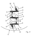
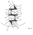
- 3 to 5 show further developments.
- the outer sides 3 (with webs 12) are arranged concave to the drum body 1 inwards between the two gripper bridges 10.
- the outer sides 3 (with webs 12) are arranged so as to be curved convexly with respect to the drum body 1 between the two gripper bridges 10, the course of curvature being formed by several straight lines.
- the outer sides 3 (with webs 12) are also curved convexly with respect to the drum body 1 to the outside between the two gripper bridges 10, the course of curvature being formed in each case by a continuous curve.
- the mode of operation is as follows: the drum body 1 is supplied with a bow from a preceding cylinder, the drum body 1 takes over the bow with its gripper bridge 10. The sheet fixed in the gripper closure is now guided from the drum body 1 into the sheet outlet and the sheet emergence and transferred to the sheet holding systems of the downstream printing cylinder. Due to the rotary movement of the drum body 1, the ambient air flows through the cassette-shaped depressions 7 and through the openings 8 and past the gripper bridges 10. Depending on the machine speed, the sheet is pressed against the sheet guiding devices 9 by centrifugal moments and guided to the transfer area. The sheet guiding devices 9 can be acted upon by suction air and / or blown air. The arch shows a smooth arch travel, without wave formation in the rear area. There is therefore no air jam on the unprinted or printed side of the sheet.
Landscapes
- Feeding Of Articles By Means Other Than Belts Or Rollers (AREA)
- Supply, Installation And Extraction Of Printed Sheets Or Plates (AREA)
- Credit Cards Or The Like (AREA)
Abstract
Description
Die Leitflächen können auch mit einer außerhalb zur Mantelfläche der Trommel angeordneten Bogenleitvorrichtung für die Bogenführung realisiert werden. Ebenso dienen die Leitflächen an der Trommel, die auch durch Leitbleche gebildet sein können zur Führung der Bogenhinterkante bei Übergabe des Bogens an den nachfolgenden Druckzylinder.
- Fig. 1
- einen Trommelkörper für zwei Greiferbrükken (3D-Darstellung),
- Fig. 2
- einen Schnitt A-A von Fig. 1,
- Fig. 3
- eine erste Weiterbildung von Figur 2,
- Fig. 4
- eine zweite Weiterbildung von Fig. 2,
- Fig. 5
- eine dritte Weiterbildung von Fig. 2.
In Fig. 3 sind die Außenseiten 3 (mit Stegen 12) konkav zum Trommelkörper 1 nach innen zwischen den beiden Greiferbrücken 10 gekrümmt angeordnet.
In Fig. 4 sind die Außenseiten 3 (mit Stegen 12) konvex zum Trommelkörper 1 nach außen zwischen den beiden Greiferbrücken 10 gekrümmt angeordnet, wobei der Krümmungsverlauf durch mehrere Geraden gebildet ist.
In Fig. 5 sind die Außenseiten 3 (mit Stegen 12) ebenso konvex zum Trommelkörper 1 nach außen zwischen den beiden Greiferbrücken 10 gekrümmt angeordnet, wobei der Krümmungsverlauf durch je eine durchgehende Kurve gebildet ist.
Durch die Drehbewegung des Trommelkörpers 1 strömt die Umgebungsluft durch die kassettenförmigen Vertiefungen 7 sowie durch die Durchbrüche 8 und an den Greiferbrücken 10 vorbei. Der Bogen wird abhängig von der Maschinengeschwindigkeit durch Zentrifugalmomente gegen die Bogenleitvorrichtungen 9 gedrückt und an diesen bis zum Übergabebereich geführt. Die Bogenleitvorrichtungen 9 sind dabei mittels Saugluft und/oder Blasluft beaufschlagbar. Der Bogen zeigt dabei einen ruhigen Bogenlauf, ohne Wellenbildung des hinteren Bereiches. Es wird somit kein Luftstau auf die unbedruckte bzw. bedruckte Seite des Bogens.
- 1
- Trommelkörper
- 2
- Stirnseite
- 3
- Außenseite
- 4
- Lagerzapfen
- 5
- Führung (für die Greiferauflage)
- 6
- Fläche
- 7
- kassettenförmige Vertiefung
- 8
- Durchbruch
- 9
- Bogenleitvorrichtung
- 10
- Greiferbrücke
- 11
- Symmetrieachse
- 12
- Steg
- I
- Ebene
- II
- Ebene
Claims (9)
- Bogenführender Trommelkörper für eine Rotationsdruckmaschine, der mittels an Stirnseiten angeordneten Trommelzapfen in Seitengestellen gelagert ist, zwei symmetrisch am Umfang angeordnete, diametral gegenüber liegende Greiferbrücken aufweist und eine innerhalb des Trommelumfanges gebildete prismatische Grundform mit Durchbrüchen aufweist, die bei Rotation von Umgebungsluft durchströmt werden,
dadurch gekennzeichnet,
dass eine Symmetrielinie (11) durch die Greiferbrücken (10) verläuft, dass rechtwinkelig zur Symmetrieachse (11) zu den Außenseiten (3) verlaufende kassettenförmige Vertiefungen (7) angeordnet sind, dass die kassettenförmigen Vertiefungen (7) Durchbrüche (8) aufweisen, die zur Symmetrieachse (11) spiegelbildlich versetzt angeordnet sind. - Bogenführender Trommelkörper nach Anspruch 1,
dadurch gekennzeichnet,
dass die Vertiefungen (7) einen derartigen Querschnitt aufweisen, dass die Außenseiten (3) durch Stege (12) gebildet sind. - Bogenführender Trommelkörper nach wenigstens Anspruch 1,
dadurch gekennzeichnet,
dass die Vertiefungen (7) zwischen den Greiferbrücken (10) in mehreren Ebenen (I,II) angeordnet sind und dass jeder Ebene (I oder II) ein Durchbruch (8) zugeordnet ist. - Bogenführender Trommelkörper nach wenigstens Anspruch 1 und 3,
dadurch gekennzeichnet,
dass in jeder Ebene (I,II) eine Vertiefung (7) die Symmetrieachse 11 schneidend angeordnet ist und die Durchbrüche (8) spiegelbildlich angeordnet sind. - Bogenführender Trommelkörper nach wenigstens Anspruch 1 und Anspruch 4,
dadurch gekennzeichnet,
dass die Durchbrüche (8) direkt an den Außenseiten (3) angeordnet sind. - Bogenführender Trommelkörper nach wenigstens Anspruch 1,
dadurch gekennzeichnet,
dass die zwischen Greiferbrücken (10) verlaufenden Außenseiten (3) gerade ausgebildet sind. - Bogenführender Trommelkörper nach wenigstens Anspruch 1,
dadurch gekennzeichnet,
dass die zwischen Greiferbrücken (10) verlaufenden Außenseiten (3) konkav zum Trommelkörper (1) nach innen gekrümmt angeordnet sind. - Bogenführender Trommelkörper nach wenigstens Anspruch 1,
dadurch gekennzeichnet,
dass die zwischen Greiferbrücken (10) verlaufenden Außenseiten (3) konvex zum Trommelkörper (1) nach außen gekrümmt angeordnet sind. - Bogenführender Trommelkörper nach wenigstens Anspruch 1,
dadurch gekennzeichnet,
dass dem Trommelkörper (1) außerhalb des Trommelumfanges eine Bogenleitvorrichtung (9) angeordnet ist.
Applications Claiming Priority (2)
| Application Number | Priority Date | Filing Date | Title |
|---|---|---|---|
| DE20001970U | 2000-02-04 | ||
| DE20001970U DE20001970U1 (de) | 2000-02-04 | 2000-02-04 | Bogenführender Trommelkörper für eine Bogenrotationsdruckmaschine |
Publications (3)
| Publication Number | Publication Date |
|---|---|
| EP1122063A2 true EP1122063A2 (de) | 2001-08-08 |
| EP1122063A3 EP1122063A3 (de) | 2003-10-01 |
| EP1122063B1 EP1122063B1 (de) | 2008-12-17 |
Family
ID=7936838
Family Applications (1)
| Application Number | Title | Priority Date | Filing Date |
|---|---|---|---|
| EP01101216A Expired - Lifetime EP1122063B1 (de) | 2000-02-04 | 2001-01-19 | Bogenführender Trommelkörper für eine Bogenrotationsdruckmaschine |
Country Status (4)
| Country | Link |
|---|---|
| EP (1) | EP1122063B1 (de) |
| JP (1) | JP3416120B2 (de) |
| AT (1) | ATE417732T1 (de) |
| DE (2) | DE20001970U1 (de) |
Citations (2)
| Publication number | Priority date | Publication date | Assignee | Title |
|---|---|---|---|---|
| DE3602084C2 (de) | 1986-01-24 | 1989-12-28 | Heidelberger Druckmaschinen Ag, 6900 Heidelberg, De | |
| DE4431114A1 (de) | 1994-09-01 | 1996-03-07 | Roland Man Druckmasch | Bogenführender Trommelkörper für eine Druckmaschine |
Family Cites Families (5)
| Publication number | Priority date | Publication date | Assignee | Title |
|---|---|---|---|---|
| DE544300C (de) * | 1929-06-25 | 1932-02-17 | Albert Schnellpressen | Verfahren und Vorrichtung zum Ausrichten der Bogen bei Mehrfarben-Rotationsdruckmaschinen |
| DE725705C (de) * | 1941-01-25 | 1942-09-28 | Willy Mailaender | Rotationsgummidruckmaschine zum mehrfarbigen Bedrucken von Blechtafeln |
| GB2268162A (en) * | 1992-06-19 | 1994-01-05 | Shinohara Machinery Co Ltd | Sheet-feeding cylinder with grippers. |
| DE4442301C5 (de) * | 1994-09-05 | 2006-12-14 | Heidelberger Druckmaschinen Ag | Bogenüberführtrommel |
| DE19949412A1 (de) | 1999-10-13 | 2001-04-19 | Heidelberger Druckmasch Ag | Einrichtung zum Wenden von Bogen in einer Bogenrotationsdruckmaschine |
-
2000
- 2000-02-04 DE DE20001970U patent/DE20001970U1/de not_active Expired - Lifetime
-
2001
- 2001-01-19 DE DE50114575T patent/DE50114575D1/de not_active Expired - Lifetime
- 2001-01-19 AT AT01101216T patent/ATE417732T1/de active
- 2001-01-19 EP EP01101216A patent/EP1122063B1/de not_active Expired - Lifetime
- 2001-02-02 JP JP2001027338A patent/JP3416120B2/ja not_active Expired - Fee Related
Patent Citations (2)
| Publication number | Priority date | Publication date | Assignee | Title |
|---|---|---|---|---|
| DE3602084C2 (de) | 1986-01-24 | 1989-12-28 | Heidelberger Druckmaschinen Ag, 6900 Heidelberg, De | |
| DE4431114A1 (de) | 1994-09-01 | 1996-03-07 | Roland Man Druckmasch | Bogenführender Trommelkörper für eine Druckmaschine |
Also Published As
| Publication number | Publication date |
|---|---|
| EP1122063A3 (de) | 2003-10-01 |
| DE20001970U1 (de) | 2000-03-23 |
| ATE417732T1 (de) | 2009-01-15 |
| DE50114575D1 (de) | 2009-01-29 |
| EP1122063B1 (de) | 2008-12-17 |
| JP3416120B2 (ja) | 2003-06-16 |
| JP2001247234A (ja) | 2001-09-11 |
Similar Documents
| Publication | Publication Date | Title |
|---|---|---|
| DE4447963B4 (de) | Einrichtung zum berührungsfreien Führen bogenförmigen Materials | |
| EP0706881B1 (de) | Bogenführungsmodul für eine Wendeeinrichtung in einer für Schön- und Widerdruck einsetzbaren Rotations-druckmaschine | |
| EP0161522A2 (de) | Bogen-Rotationsdruckmaschine für einseitigen Mehrfarbendruck oder Schön- und Widerdruck | |
| EP0703072B1 (de) | Bogenüberführtrommel | |
| EP0922574B1 (de) | Bogenführungseinrichtung in einer Druckmaschine | |
| DE10102733B4 (de) | Einrichtung zur Überführung eines Bogens | |
| EP0607538A1 (de) | Druckmaschine mit bogenführender Fläche | |
| DE10358171A1 (de) | Vorrichtung zum Fördern eines Bogens durch eine drucktechnische Maschine | |
| DE10102221A1 (de) | Vorrichtung zum Verlangsamen von Signaturen | |
| DE10060557B4 (de) | Bogenleiteinrichtung in einer Rotationsdruckmaschine | |
| DE102009000218B4 (de) | Auslage einer bogenverarbeitenden Maschine mit einem Bogenfördersystem zum Übernehmen der Bogen von einem Bogenführungszylinder | |
| EP0699528B1 (de) | Bogenführender Trommelkörper für eine Druckmaschine | |
| EP0706882B1 (de) | Bogenführender Trommelkörper für eine Druckmaschine | |
| EP1122063B1 (de) | Bogenführender Trommelkörper für eine Bogenrotationsdruckmaschine | |
| DE102006030062B3 (de) | Bogenführungszylinder mit Aufzug in einer Verarbeitungsmaschine | |
| EP1424196B1 (de) | Greifsystemkörper zum Fördern von Bogen in Bogendruckmaschinen | |
| DE4342203C3 (de) | Einrichtung zum Einwirken auf Bogen in einer Bogenrotationsdruckmaschine | |
| EP0662439A1 (de) | Pneumatische Bogenleiteinrichtung | |
| DE102009019020B4 (de) | Vorrichtung zum Wenden eines Bogen während des Förderns durch eine Druckmaschine | |
| EP1319505A2 (de) | Bogenleiteinrichtung in einer Verarbeitungsmaschine | |
| DD253020A1 (de) | Leiteinrichtung in auslegern von bogendruckmaschinen | |
| DE10222060B4 (de) | Bogenführungstrommel in einer Druckmaschine und Bogendruckmaschine | |
| DE102006060686B4 (de) | Vorrichtung zum Fördern eines Bogens durch eine drucktechnische Maschine | |
| DE4448055B4 (de) | Bogenüberführtrommel | |
| DE19753068A1 (de) | Bogenführungseinrichtung in einer Druckmaschine |
Legal Events
| Date | Code | Title | Description |
|---|---|---|---|
| PUAI | Public reference made under article 153(3) epc to a published international application that has entered the european phase |
Free format text: ORIGINAL CODE: 0009012 |
|
| AK | Designated contracting states |
Kind code of ref document: A2 Designated state(s): AT BE CH CY DE DK ES FI FR GB GR IE IT LI LU MC NL PT SE TR |
|
| AX | Request for extension of the european patent |
Free format text: AL;LT;LV;MK;RO;SI |
|
| PUAL | Search report despatched |
Free format text: ORIGINAL CODE: 0009013 |
|
| AK | Designated contracting states |
Kind code of ref document: A3 Designated state(s): AT BE CH CY DE DK ES FI FR GB GR IE IT LI LU MC NL PT SE TR |
|
| AX | Request for extension of the european patent |
Extension state: AL LT LV MK RO SI |
|
| RIC1 | Information provided on ipc code assigned before grant |
Ipc: 7B 41F 13/08 B Ipc: 7B 41F 21/10 A |
|
| 17P | Request for examination filed |
Effective date: 20030823 |
|
| AKX | Designation fees paid |
Designated state(s): AT DE FR GB |
|
| 17Q | First examination report despatched |
Effective date: 20050830 |
|
| RAP1 | Party data changed (applicant data changed or rights of an application transferred) |
Owner name: MANROLAND AG |
|
| GRAP | Despatch of communication of intention to grant a patent |
Free format text: ORIGINAL CODE: EPIDOSNIGR1 |
|
| GRAS | Grant fee paid |
Free format text: ORIGINAL CODE: EPIDOSNIGR3 |
|
| GRAA | (expected) grant |
Free format text: ORIGINAL CODE: 0009210 |
|
| AK | Designated contracting states |
Kind code of ref document: B1 Designated state(s): AT DE FR GB |
|
| REG | Reference to a national code |
Ref country code: GB Ref legal event code: FG4D Free format text: NOT ENGLISH |
|
| REF | Corresponds to: |
Ref document number: 50114575 Country of ref document: DE Date of ref document: 20090129 Kind code of ref document: P |
|
| PLBE | No opposition filed within time limit |
Free format text: ORIGINAL CODE: 0009261 |
|
| STAA | Information on the status of an ep patent application or granted ep patent |
Free format text: STATUS: NO OPPOSITION FILED WITHIN TIME LIMIT |
|
| 26N | No opposition filed |
Effective date: 20090918 |
|
| GBPC | Gb: european patent ceased through non-payment of renewal fee |
Effective date: 20090317 |
|
| REG | Reference to a national code |
Ref country code: FR Ref legal event code: ST Effective date: 20091030 |
|
| PG25 | Lapsed in a contracting state [announced via postgrant information from national office to epo] |
Ref country code: GB Free format text: LAPSE BECAUSE OF NON-PAYMENT OF DUE FEES Effective date: 20090317 Ref country code: FR Free format text: LAPSE BECAUSE OF NON-PAYMENT OF DUE FEES Effective date: 20090217 |
|
| PGFP | Annual fee paid to national office [announced via postgrant information from national office to epo] |
Ref country code: DE Payment date: 20120210 Year of fee payment: 12 |
|
| REG | Reference to a national code |
Ref country code: DE Ref legal event code: R081 Ref document number: 50114575 Country of ref document: DE Owner name: MANROLAND SHEETFED GMBH, DE Free format text: FORMER OWNER: MANROLAND AG, 63075 OFFENBACH, DE Effective date: 20120509 |
|
| PGFP | Annual fee paid to national office [announced via postgrant information from national office to epo] |
Ref country code: AT Payment date: 20120120 Year of fee payment: 12 |
|
| REG | Reference to a national code |
Ref country code: AT Ref legal event code: MM01 Ref document number: 417732 Country of ref document: AT Kind code of ref document: T Effective date: 20130131 |
|
| PG25 | Lapsed in a contracting state [announced via postgrant information from national office to epo] |
Ref country code: DE Free format text: LAPSE BECAUSE OF NON-PAYMENT OF DUE FEES Effective date: 20130801 Ref country code: AT Free format text: LAPSE BECAUSE OF NON-PAYMENT OF DUE FEES Effective date: 20130131 |
|
| REG | Reference to a national code |
Ref country code: DE Ref legal event code: R119 Ref document number: 50114575 Country of ref document: DE Effective date: 20130801 |