EP1120999A2 - Haushaltsgerät, insbesondere Haushaltsgargerät - Google Patents
Haushaltsgerät, insbesondere Haushaltsgargerät Download PDFInfo
- Publication number
- EP1120999A2 EP1120999A2 EP00125468A EP00125468A EP1120999A2 EP 1120999 A2 EP1120999 A2 EP 1120999A2 EP 00125468 A EP00125468 A EP 00125468A EP 00125468 A EP00125468 A EP 00125468A EP 1120999 A2 EP1120999 A2 EP 1120999A2
- Authority
- EP
- European Patent Office
- Prior art keywords
- housing
- appliance according
- household appliance
- control
- display device
- Prior art date
- Legal status (The legal status is an assumption and is not a legal conclusion. Google has not performed a legal analysis and makes no representation as to the accuracy of the status listed.)
- Granted
Links
- 238000010411 cooking Methods 0.000 title claims description 8
- 238000007789 sealing Methods 0.000 claims description 17
- 239000011521 glass Substances 0.000 claims description 9
- 238000010438 heat treatment Methods 0.000 claims description 4
- 239000002861 polymer material Substances 0.000 claims description 4
- 230000001427 coherent effect Effects 0.000 claims description 3
- 239000013013 elastic material Substances 0.000 claims description 3
- 239000002241 glass-ceramic Substances 0.000 claims description 3
- 238000000465 moulding Methods 0.000 claims description 2
- -1 Polyoxymethylen Polymers 0.000 description 11
- 229920006324 polyoxymethylene Polymers 0.000 description 6
- 125000006850 spacer group Chemical group 0.000 description 6
- 229920001577 copolymer Polymers 0.000 description 5
- 239000004642 Polyimide Substances 0.000 description 4
- 229920000265 Polyparaphenylene Polymers 0.000 description 4
- 229920006260 polyaryletherketone Polymers 0.000 description 4
- 229920001721 polyimide Polymers 0.000 description 4
- 239000004734 Polyphenylene sulfide Substances 0.000 description 3
- 238000011161 development Methods 0.000 description 3
- 230000018109 developmental process Effects 0.000 description 3
- 230000005484 gravity Effects 0.000 description 3
- 239000000463 material Substances 0.000 description 3
- 239000004033 plastic Substances 0.000 description 3
- 229920003023 plastic Polymers 0.000 description 3
- 229920000069 polyphenylene sulfide Polymers 0.000 description 3
- CBCKQZAAMUWICA-UHFFFAOYSA-N 1,4-phenylenediamine Chemical compound NC1=CC=C(N)C=C1 CBCKQZAAMUWICA-UHFFFAOYSA-N 0.000 description 2
- 229930182556 Polyacetal Natural products 0.000 description 2
- 239000004952 Polyamide Substances 0.000 description 2
- 239000004698 Polyethylene Substances 0.000 description 2
- 239000004743 Polypropylene Substances 0.000 description 2
- QQONPFPTGQHPMA-UHFFFAOYSA-N Propene Chemical compound CC=C QQONPFPTGQHPMA-UHFFFAOYSA-N 0.000 description 2
- 229910000831 Steel Inorganic materials 0.000 description 2
- 238000007600 charging Methods 0.000 description 2
- 238000013461 design Methods 0.000 description 2
- 230000000694 effects Effects 0.000 description 2
- 230000005489 elastic deformation Effects 0.000 description 2
- 238000007786 electrostatic charging Methods 0.000 description 2
- 238000003780 insertion Methods 0.000 description 2
- 230000037431 insertion Effects 0.000 description 2
- 238000009413 insulation Methods 0.000 description 2
- 238000004519 manufacturing process Methods 0.000 description 2
- 238000012986 modification Methods 0.000 description 2
- 230000004048 modification Effects 0.000 description 2
- 229920002647 polyamide Polymers 0.000 description 2
- 229920000573 polyethylene Polymers 0.000 description 2
- 229920000642 polymer Polymers 0.000 description 2
- 229920001155 polypropylene Polymers 0.000 description 2
- 238000003825 pressing Methods 0.000 description 2
- 239000010959 steel Substances 0.000 description 2
- FPWNLURCHDRMHC-UHFFFAOYSA-N 4-chlorobiphenyl Chemical compound C1=CC(Cl)=CC=C1C1=CC=CC=C1 FPWNLURCHDRMHC-UHFFFAOYSA-N 0.000 description 1
- 229920002943 EPDM rubber Polymers 0.000 description 1
- 229930040373 Paraformaldehyde Natural products 0.000 description 1
- 239000004696 Poly ether ether ketone Substances 0.000 description 1
- 239000004793 Polystyrene Substances 0.000 description 1
- 230000004308 accommodation Effects 0.000 description 1
- 229920006222 acrylic ester polymer Polymers 0.000 description 1
- 230000005540 biological transmission Effects 0.000 description 1
- 229910052799 carbon Inorganic materials 0.000 description 1
- 239000000969 carrier Substances 0.000 description 1
- YACLQRRMGMJLJV-UHFFFAOYSA-N chloroprene Chemical compound ClC(=C)C=C YACLQRRMGMJLJV-UHFFFAOYSA-N 0.000 description 1
- 238000013016 damping Methods 0.000 description 1
- 230000001419 dependent effect Effects 0.000 description 1
- RTZKZFJDLAIYFH-UHFFFAOYSA-N ether Substances CCOCC RTZKZFJDLAIYFH-UHFFFAOYSA-N 0.000 description 1
- 229920002313 fluoropolymer Polymers 0.000 description 1
- 150000008282 halocarbons Chemical class 0.000 description 1
- 238000001746 injection moulding Methods 0.000 description 1
- 238000002955 isolation Methods 0.000 description 1
- 150000002576 ketones Chemical class 0.000 description 1
- 239000002184 metal Substances 0.000 description 1
- 210000001331 nose Anatomy 0.000 description 1
- 229920000090 poly(aryl ether) Polymers 0.000 description 1
- 229920001200 poly(ethylene-vinyl acetate) Polymers 0.000 description 1
- 229920002530 polyetherether ketone Polymers 0.000 description 1
- 229920001343 polytetrafluoroethylene Polymers 0.000 description 1
- 239000004810 polytetrafluoroethylene Substances 0.000 description 1
- 125000004805 propylene group Chemical group [H]C([H])([H])C([H])([*:1])C([H])([H])[*:2] 0.000 description 1
- RTHVZRHBNXZKKB-UHFFFAOYSA-N pyrazine-2,3,5,6-tetracarboxylic acid Chemical compound OC(=O)C1=NC(C(O)=O)=C(C(O)=O)N=C1C(O)=O RTHVZRHBNXZKKB-UHFFFAOYSA-N 0.000 description 1
- BFKJFAAPBSQJPD-UHFFFAOYSA-N tetrafluoroethene Chemical group FC(F)=C(F)F BFKJFAAPBSQJPD-UHFFFAOYSA-N 0.000 description 1
- 239000012815 thermoplastic material Substances 0.000 description 1
- 239000012780 transparent material Substances 0.000 description 1
- 238000005406 washing Methods 0.000 description 1
Images



Classifications
-
- H—ELECTRICITY
- H05—ELECTRIC TECHNIQUES NOT OTHERWISE PROVIDED FOR
- H05B—ELECTRIC HEATING; ELECTRIC LIGHT SOURCES NOT OTHERWISE PROVIDED FOR; CIRCUIT ARRANGEMENTS FOR ELECTRIC LIGHT SOURCES, IN GENERAL
- H05B3/00—Ohmic-resistance heating
- H05B3/68—Heating arrangements specially adapted for cooking plates or analogous hot-plates
- H05B3/74—Non-metallic plates, e.g. vitroceramic, ceramic or glassceramic hobs, also including power or control circuits
-
- F—MECHANICAL ENGINEERING; LIGHTING; HEATING; WEAPONS; BLASTING
- F24—HEATING; RANGES; VENTILATING
- F24C—DOMESTIC STOVES OR RANGES ; DETAILS OF DOMESTIC STOVES OR RANGES, OF GENERAL APPLICATION
- F24C7/00—Stoves or ranges heated by electric energy
- F24C7/08—Arrangement or mounting of control or safety devices
- F24C7/082—Arrangement or mounting of control or safety devices on ranges, e.g. control panels, illumination
Definitions
- the invention relates to a household appliance, in particular a Household cooking appliance.
- a control module with operating elements, display elements and control electronics which can be installed in a stove and is provided for controlling the hotplates and / or the oven of the stove.
- the control elements and the display elements are electrically contacted and arranged on a first circuit board and the control electronics on a second circuit board.
- the two printed circuit boards are fastened together and electrically connected to one another by means of a plug connection.
- On the underside of the second printed circuit board facing away from the first printed circuit board there is a mains voltage supply as well as a plurality of flat plugs projecting downwards from the second printed circuit board for connecting the control module to hotplates of the cooker.
- a control unit for a cooking surface with several separately heatable hotplates is known from DE 44 19 866 A1 .
- the control unit comprises a sensor circuit board, on the top of which faces the glass plate of the hob, a plurality of sensor surfaces of actuating elements for controlling the electrical consumers of the hotplates are provided.
- Control electronics for the electrical consumers controlled by the actuating elements is arranged on a further printed circuit board arranged parallel to the sensor printed circuit board and on the side facing away from the glass plate.
- the two circuit boards are electrically connected to each other via electrically conductive springs that press the sensor circuit board against the glass plate under spring tension.
- Flat tabs for connecting the power supply line are also arranged on the underside of the second printed circuit board.
- the two interconnected circuit boards with the correspondingly arranged elements are arranged in a common housing which is glued to the glass plate of the hob from below.
- the housing has an end cover on the side facing away from the glass plate, which can be screwed on using screws. After attaching the end cover, the housing is closed and the control unit is protected against the ingress of moisture. To make electrical contact with the control unit, the end cover must be removed by loosening the screws.
- the invention is based on the object of a household appliance with an easy to install control and / or Specify display unit.
- the control and / or display device is through the housing against external influences, especially electrostatic Charging (ESD) protected from contact or dirt and forms a preassembled together with the housing Control and / or display unit.
- ESD electrostatic Charging
- the assembly of this Unity is through the detachable and form-fitting or non-positive connection between extension and receptacle particularly simple because the housing is simply attached to the carrier can be placed and fixed at the same time and none additional connections are required more.
- the control and / or display device through a loading opening (passage opening) into the Housing can be inserted and on a support area (support base) of the housing can be placed or placed in such a way that the actuating element and / or the display element for the loading opening are arranged or is or in or protrude through the loading opening,
- the carrier device preferably has at least one Contact surface for the housing on top, so opposite gravitational force.
- the housing is thus from above on the carrier device hung up, for fixing each extension in the associated Engaging recess or opening, and is by gravity - and possibly one additional rectified pressing force - on the carrier device held and by the fixation on one prevented from sliding sideways.
- connection between the extension and the recess or opening can in particular essentially in the direction of gravity (Gravity) so that hanging up and fixing the housing on the carrier device can be accomplished with a single movement.
- connection can also have a certain weight the control and / or display unit (control and / or Display device with housing) and the Unit can also be mounted on a vertical or sloping support wall be attached.
- the interior of the housing is one in Essentially closed housing side wall and one the housing bottom opposite the loading opening.
- the interior is in this embodiment practically only on the open side through the charging opening for the control and / or display device accessible.
- This closed structure offers the best Protection of the control and / or display device against influences from the outside.
- a preferred shape for the housing side wall is the trapezoidal shape.
- the household appliance are at least one extension and / or at least in the housing a shot at one of the loading opening facing away from the housing. Moreover is preferably at least one of those assigned to the housing Extensions or receptacles on the housing side wall or arranged or formed on the housing base.
- At least the control and / or display device an electrical plug contact element for connecting electrical lines and the housing has at least one Through opening for.
- the plug contact elements are thus through the housing wall passed through and can therefore from outside the Housing easily with a corresponding plug contact element a connection cable.
- the control and / or display device with the complete Housing as a pre-assembled unit initially under the hob and then after completed assembly only the electrical contacting of the Connection cables are made.
- manufacturing processes which are tax and / or Display unit is a supplier part, is thus a Simplification and easier assembly.
- the housing wall can also be a cable holder (Cable entry), preferably with a cable strain relief, for one or more electrical cables for connection to have the plug-in contact elements.
- a cable holder preferably with a cable strain relief, for one or more electrical cables for connection to have the plug-in contact elements.
- control and / or Display device on her of the actuator or display element facing away (bottom) further electrical or electronic components, whereby the housing wall is adjusted accordingly so that these components are spaced from the housing wall, if the control and / or display device in the interior the housing is inserted ..
- the housing is preferably made of a coherent Molding formed, so that no additional assembly steps for assembling or screwing the housing together are more needed.
- the preferred material for the housing is one of those in or on the household appliance Temperature resistant polymer material (plastic) .
- the housing wall is particularly advantageous Embodiment at least partially double-walled, for better thermal insulation from the outside environment to reach the housing.
- the housing part walls can in particular via at least one connecting web be connected.
- a further development of the household appliance is through a cover to cover the feed opening of the housing characterized.
- the cover is preferably on the housing in the area surrounding the loading opening or to a charging opening provided in this area surrounding seal can be placed or placed.
- the seal for sealing the housing on the cover is preferably between the spaced apart housing part walls arranged.
- Means can be provided for pressing the housing or the Seal and / or the display elements or actuators the control and / or display device to the cover, in particular at least one spring element, for example made of elastic steel.
- the cover for the case is now special advantageous embodiment a detachable on the housing, preferably in the space between the housing part walls, fastenable or fastened, in particular latchable or snappable or snapped or snapped, Sealing cover.
- This embodiment with ' Sealing cover is especially for transporting the tax and / or display unit advantageous because of the housing inserted control and / or display device the housing and the lid all around against external influences is protected, especially against electrostatic charge, the damage to electronic components of the control and / or Display device would lead. After transportation and / or by removing the cover with the housing be installed in the household appliance.
- the cover can in another embodiment with one, in particular Hob made of glass or glass ceramic the hob for setting up food containers his.
- the control and / or display device is then generally for the cooktop (and / or possibly for one assigned oven) provided.
- the carrier device for the housing is preferably at least partially below the hob arranged support pan in which there is also at least one heating device (e.g. radiant heater) of the hob is arranged. But it can also be one of the supports for the heating devices independent carrier device may be provided, for example both carriers can be arranged side by side.
- FIGS. 1 to 12 provided the same reference numerals.
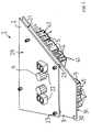
- the control and / or display device (circuit board arrangement) for a hob according to FIG 1 essentially comprises two Printed circuit boards 2 arranged parallel to one another and 3, which are spaced apart from one another via connecting elements 23 are connected.
- Top 20 of the circuit board 2 are several display elements, especially seven-segment LED displays, 22 arranged and electrically contacted.
- the opposite Underside of the circuit board 2 is designated 21.
- the the first circuit board 2 facing the top of the second Printed circuit board 3 is designated 30, while that of the Top side 30 facing away from the bottom with 31 of the circuit board 3 is designated.
- On the top 20 of the first circuit board 2 a plurality of spacers 6 are arranged.
- the spacers 6 preferably consist of a flexible (deformable) material.
- the entire control and / or display device 1 can now with the spacers 6 against a - not shown - hob, for example made of glass or a glass ceramic, are pressed until the Display elements 22 rest against the hob from below, for good visibility of the displayed symbols or, as in the illustrated embodiment, over seven Allow segments to display digits.
- the spacers 6 of the control and / or display device 1 can also touch sensors in all embodiments included, so that they can also be used as operating elements (operating switches) for setting the operating states of the Cooktop can be used.
- control components 5, 7 and 9 On the underside 31 of the second circuit board 3 of the control and / or Display device 1 are several electronic or electrical control components 5, 7 and 9 arranged.
- three control components form 5, two control components 7 and two control components 9 on each side of the trapezoidal second PCB 3 each an assembly.
- the control components 5, 7 and 9 can in particular electronic components and / or contain electrical components, in particular Switching relay for switching the supply current for the - Heating devices of cooking zones, not shown Cooktop or just a corresponding switching signal, and / or a microprocessor with corresponding Auxiliary components.
- each parallel contact groups 40 to 44 arranged to the edges.
- Each of the contact groups 40 to 44 comprises plug contact elements 4, the second circuit board 3 in protrude essentially vertically downwards. Via the plug contact elements 4 of each contact group is 40 to 44 respectively a sealing mat 8 inserted.
- the plug contact elements are from a narrower contact part 4 "and an immediate arranged on the second circuit board 3 base part 4 'constructed.
- the sealing mat 8 has one of the number the plug contact elements 4 of the corresponding contact group 40 to 44 corresponding number of slots (through opening) through which the respective contact parts 42 ' can be inserted, but which are smaller than the base parts 4 ', so that the sealing mats 8 Base parts 4 'of the plug contact elements 4 are seated.
- the Sealing mats 8 are preferably made of an elastic Material so that the slots are made a little smaller can be used as the contact parts 42 'of the plug contact elements 4 and thus the sealing mats 8 under one Spring tension (elastic deformation force) on the plug contact elements 4 held each contact group 40 to 44 become.
- the housing 10 shown in Figures 3 and 4 is for accommodation and assembling one. - In Figures 3 and 4 not shown - control and / or display device 1 according to Figures 1 and 2 provided and designed.
- the housing 10 laterally has two substantially parallel to each other running, also trapezoidal, walls. An inner one Sidewall is designated 11, while the outer Sidewall is designated 12.
- the housing 10 is after above to a hob plate (not shown) open, causing particular between the inner side wall 11 and the outer side wall 12 a gap (space) 19 and a loading opening within the inner side wall 11 (Access opening) are formed.
- the gap 19 serves the thermal Isolation of the housed in the housing 10 temperature sensitive electronic components on the Control and / or display device 1.
- a circumferential support base 14 for the control and / or display device 1 is arranged.
- a support base (support surface) 13 On the two sloping sides of the trapezoidal Housing 10 is formed a support base (support surface) 13, on which the control and / or display device 1 is also launched.
- Trapezoidal edges of the inner side wall 11 closes a lower part of the support base 13 in which also an opening 140 for the contact group 40 of the Control and / or display device 1 is formed.
- One in the trailing part of the trapezoidal Housing 10 arranged bottom part is with 16 and one arranged in the tapered part of the housing 10 second bottom part designated 17.
- the bottom part 17 is arranged higher than the bottom part 16, so that a stair or step-shaped housing bottom realized is.
- On the inner side wall 11 there are also latching or Snap elements 15 arranged for releasable attachment the control and / or display device 1. That of the housing base parts 16 and 17 and the side walls 11 and 18 limited interior of the housing 10 for receiving the control and / or display device 1 is designated by 25.
- extensions projections, Noses
- the carrier device 80 in a support area for the housing 10 for each extension 61 an associated, in the outline of the Extension 61 adapted receptacle 81 into which the extension 61 engages positively.
- the housing 10 of the carrier device 80 worn and at the same time against lateral Secured slipping.
- the connection pairs from each form an extension 61 and a receptacle 81 releasable fixing means for fixing the housing 10 to the Carrier device 80.
- the shape and shape of the extensions 61 and the receptacles 81 is of course not on the illustrated embodiment limited, but can be varied in many ways, depending of the desired fixing effect.
- a positive connection between the extension 61 and receptacle 81 which in one direction, namely the bearing direction, is unsecured
- a non-positive Connection or a snap or snap connection realized be to prevent the housing 10 from accidental Detach from the carrier device 80 in all directions, that is also in the support direction.
- You can also also in kinematic reversal of extensions on the carrier device 80 and recordings provided on the housing 10 his.
- the recordings 81 can through openings or also be closed recesses below. If the carrier device 80 from a metal sheet, in particular one Sheet steel, is formed, the openings can simply be punched his. Furthermore, extensions can be exhibited Rag formed.
- FIGS. 5 and 6 now show one in a housing 10 according to 3 and 4 mounted control and / or display device 1 according to FIGS 1 and 2.
- the lower, second circuit board 3 lies with its underside 31 (in FIGS. 5 and 6 not visible) on the support bases 13 and 14.
- the Top 20 of the upper circuit board 2 is up to open side of the housing 10 directed so that the Spacer 6 a little over the top of the case 10 protrude upwards.
- a circumferential seal 29 is inserted from above, those mounted below a hob Housing 10 with a control and / or display device mounted therein 1 is against the hob plate from below and the control and / or display device 1 against intrusion sealed from moisture and dirt.
- the contact blocks 40 to 44 are each through the associated openings 140 to 144 in the Wall of the housing 10 guided so that the contact parts 42 'of the plug contact elements 4 down from the housing 10 protrude.
- the sealing mats 8 are on the inside of the support base 13 and seal the openings 140 to 144 respectively at their edges, so that also through the openings 140 to 144 no moisture or dirt in the interior 25 of the housing to the sensitive electronic Components on the control and / or display device 1 can reach.
- the lower control components 5 and 9 protrude in the lower area of the housing interior delimited by the base part 16 25 while the flatter control components 7 in the limited by the bottom part 17 down Lower region of the interior 25 of the housing 10 is arranged become.
- the elastic spacers 6 are Damping also on the support base 13 of the housing 10 on.
- For fastening the control and / or display device 1 latch the locking elements 15 on the inner side wall 11 of the housing 10 in the space between the two circuit boards 2 and 3 or below the circuit board 3rd
- the control and / or display device 1 does not have to be in the housing 10 snapped or locked, but can also just be inserted into the housing 10. Through the flush arrangement of the housing 10 between the bottom of the Trough tray and the cooktop is the control and / or Display device 1 held firmly and securely.
- Openings 140 to 144 as well as that provided at the top The opening 10 is thus closed and surrounded by a double wall for thermal insulation. This is a good protection of the control and / or display device 1 and its electrical and electronic Guaranteed components against heat, moisture and dirt.
- a cable holder 60 provided with a cutout and a bendable element for closing the cutout.
- This cable holder 60 becomes the electrical wires (Cable), which are provided at the ends of the plug contact sockets with the plug contact elements 4 electrically be contacted and for the electrical supply of the Control and / or display device 1 and optionally also intended for the transmission of electrical signals are.
- These lines are designated 62 in FIG. 5.
- FIGS 7 to 10 is in a different views 3 and 4 somewhat modified housing 10 for a - not shown - control and / or display device 1 shown. It is not a circular support base 14 provided, but there are several individual support frames 13, 13 'and 13 "provided on which the control and / or Display device 1 is placed. Three openings for on the underside of the control and / or display device Contact groups provided are 55, 56 and 57 designated.
- the housing 10 again has a trapezoidal shape Double wall made of inner side wall 11 and outer side wall 12 on a horizontal, transverse to the walls Connecting web 58 are interconnected. 69. On the shorter of the two sides parallel to each other the trapeze is in the outer side wall 12 again Cable bracket 60 provided.
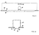
- extension 91 projecting downward is formed or molded, its shape can be seen in more detail in FIG is.
- the extension 91 engages in an opening 85 in the sheet the carrier device 80.
- the extension 91 has on the side two bevels 92 and 93 as guides for insertion of the extension 91 in the opening 85 to facilitate. From the correspondingly narrower cross-section at the outermost The extension 91 widens in its cross section up to a particularly cuboid inner area with a constant cross-section, which is form-fitting on the Opening 85 abuts from the inside.
- the deepest bottom part is 16 of the housing 10 through a further opening 86 in the carrier device 80 performed, with no positive locking achieved must become.
- this area in the housing 10 more space for components of the control and / or display device 1 can be provided.
- the design of the control and / or display unit according to The invention has the advantage that the control and / or Display device 1 are pre-assembled in the housing 10 can and then transported as a transport unit and / or can be mounted as a mounting unit on the hob.
- the lid 70 has one upper flat side on and an edge bent over and is trapezoidal in shape to the housing 10 customized.
- On the longer of the two parallel sides of the Trapezes of the cover 70 are two locking lugs (locking hooks) 72 and 73 formed in locking openings 67 and 68 of the housing 10 (shown in FIG 7 and 8) engage with a click.
- a further locking lug (locking hook) 71 is provided, the into a locking opening 95 of the housing 10 above the cable holder 60 engages .
- the cover 70 is thus latching or snap-connectable to the housing 10, so that the Housing 10 pre-assembled - not shown - control and / or Display device 1 is also protected from above.
- the cover 70 also has a tab 74 as a handle to release the cover 70 from the housing 10.
- some downwardly projecting cylindrical connector 75 provided for Support the or on the control and / or display device 1.
- the lid 70 facilitates assembly and the Transport of the control and / or display device 1.
- the lid 70 protects the electronics of the control and / or display device 1 now against external influences such as electrostatic charging by touch, mechanical influences or Dirt.
- the control and / or display device 1, the housing 10 and the cover 70 can now together as pre-assembled Unit can be transported. This unity remains then preferably also when installing the electrical cable plug contact sockets to the outside of the housing 10 projecting plug contact elements 4 received. So can unity for example, be placed on the lid 70.
- the Stubs 75 of the cover 70 support the control and / or Display device 1 and take the plug acting insertion forces. After the electrical contact the cover 70 is then removed and the remaining one Unit from control and / or display device 1 and housing 10 is then in the carrier pan of the hob assembled.
- the described control and / or display device 1 can as a control and / or display device not only for one Cooktop, but with corresponding modifications used for other household appliances, for example for other cooking devices, such as ovens, cookers or microwave ovens, or for washing machines, tumble dryers or dishwashers, where instead of the hob as Cover for the loading opening from a cover plate transparent material such as glass can be provided. Also can not shown spring elements or the like be provided, in particular between the housing 10 and the control and / or display device 1 can be arranged and the display elements 22 towards or against the Press cover.
- Plastics such as polyethylene (PE), polypropylene (PP), polystyrene (PS) and others be used.
- the housing 10 and the lid 70 are preferably each manufactured as a coherent (one-piece) molded body, especially - with thermoplastic materials - through an injection molding process that offers a high degree of design freedom allowed.
Landscapes
- Engineering & Computer Science (AREA)
- Chemical & Material Sciences (AREA)
- Ceramic Engineering (AREA)
- Combustion & Propulsion (AREA)
- Mechanical Engineering (AREA)
- General Engineering & Computer Science (AREA)
- Cookers (AREA)
- Baking, Grill, Roasting (AREA)
- Electric Stoves And Ranges (AREA)
Abstract
Description
- FIG 1
- eine Steuer- und/oder Anzeigevorrichtung mit mehreren Anzeigeelementen in einer perspektivischen Ansicht von oben und
- FIG 2
- die Steuer- und/oder Anzeigevorrichtung gemäß FIG 1 in einer perspektivischen Ansicht von unten,
- FIG 3
- ein Gehäuse für eine Steuer- und/oder Anzeigevorrichtung gemäß der FIG 1 und 2 auf einer Trägereinrichtung in einer perspektivischen Ansicht von oben und
- FIG 4
- das Gehäuse gemäß FIG 3 in einer perspektivischen Ansicht von unten,
- FIG 5
- das Gehäuse gemäß den FIG 3 und 4 mit einer montierten Steuer- und/oder Anzeigevorrichtung gemäß den FIG 1 und 2 in einer perspektivischen Ansicht von schräg oben und
- FIG 6
- die Kombination aus Gehäuse und Steuer- und/oder Anzeigevorrichtung gemäß FIG 5 in einer perspektivischen Ansicht von unten,
- FIG 7
- eine weitere Ausführungsform eines Gehäuses in einer perspektivischen Ansicht von oben,
- FIG 8
- das Gehäuse gemäß FIG 7 in einer perspektivischen Ansicht von unten,
- FIG 9
- das auf eine Trägereinrichtung aufgesetzte Gehäuse gemäß FIG 7 und 8 in einer teilweise geschnittenen Frontansicht auf die kürzere Seite,
- FIG 10
- das auf eine Trägereinrichtung aufgesetzte Gehäuse gemäß FIG 7 und 8 in einem Ausschnitt aus einer teilweise geschnittenen Frontansicht auf die längere Seite.
- FIG 11
- einen Verschlußdeckel für ein Gehäuse zur Aufnahme einer Steuer- und/oder Anzeigevorrichtung in einer perspektivischen Ansicht von oben und
- FIG 12
- den Verschlußdeckel gemäß FIG 11 in einer perspektivischen Ansicht von unten.
- Polyimide (PI), insbesondere Polymethacrylimid (PMI) oder das aus Pyrazin-Tetracarbonsäure-Anhydrid und Diaminot-hiodiazol hergestellte PPDA,
- Polyoxymethylen (Polyacetal, POM) für nicht zu hohe Temperaturen,
- Polyamide,
- PA 6.6
- Halogen-Kohlenstoff-Polymere, insbesondere fluorierte oder anders halogenierte Kohlenwasserstoffe , insbesondere Fluorcarbon-Polymere oder Copolymere, beispielsweise Polyfluorethylene, insbesondere Polytetrafluorethylen oder ein Copolymer aus Tetrafluorethylen und Propylen, oder Chlorbutadien-Polymere
- Acrylester-Polymere,
- Ethylen-Propylen-Dien-Elastomere
- Ethylen-Vinylacetat-Copolymere
- Polyphenylen (PPH).
- Polyphenylensulfid (PPS)
- Polyaryletheretherketon (PEEK) und Abwandlungen wie Polyaryletherketon (PAEK) und Polyetheretherketonketon (PEEKK)
Claims (25)
- Haushaltsgerät, insbesondere Haushaltsgargerät, mita) einer Steuer- und/oder Anzeigevorrichtung (1) mit wenigstens einem Betätigungselement (6) und/oder wenigstens einem Anzeigeelement (22),b) einem Gehäuse (10) für die Steuer- und/oder Anzeigevorrichtung.,c) einer Trägereinrichtung (80) für das Gehäuse, wobeid) das Gehäuse wenigstens einen Fortsatz (61, 91) und/oder wenigstens eine Aufnahme, insbesondere eine Ausnehmung oder eine Öffnung, aufweist, der bzw. die mit einer korrespondierenden Aufnahme (81,85) bzw. einem Fortsatz der Trägereinrichtung in Eingriff bringbar oder gebracht ist zum Fixieren des Gehäuses relativ zur Trägereinrichtung zumindest in zwei Raumrichtungen.
- Haushaltsgerät nach Anspruch 1, bei dem das Gehäuse eine Beschickungsöffnung und wenigstens einen Auflagebereich in einem Innenraum des Gehäuses aufweist, wobei die Steuer- und/oder Anzeigevorrichtung (1) durch die Beschickungsöffnung in den Innenraum des Gehäuses (10) einbringbar ist und auf dem Auflagebereich des Gehäuses derart auflegbar oder aufgelegt ist, dass das Betätigungselement und/oder das Anzeigeelement zur Beschickungsöffnung hin angeordnet sind bzw. ist oder in oder durch die Beschickungsöffnung ragen bzw. ragt,
- Haushaltsgerät nach Anspruch 2, bei dem wenigstens ein Fortsatz und/oder wenigstens eine Aufnahme an einer von der Beschickungsöffnung abgewandten Seite des Gehäuses angeordnet sind bzw. ist.
- Haushaltsgerät nach Anspruch 2 oder Anspruch 3, bei dem der Innenraum des Gehäuses von einer im Wesentlichen geschlossenen Gehäuseseitenwandung, die insbesondere trapezförmig gestaltet ist, und einem der Beschickungsöffnung gegenüberliegenden Gehäuseboden begrenzt ist.
- Haushaltsgerät nach Anspruch 4, bei dem wenigstens einer der dem Gehäuse zugeordneten Fortsätze oder Aufnahmen an der Gehäuseseitenwandung oder am Gehäuseboden angeordnet oder ausgebildet ist.
- Haushaltsgerät nach einem der vorhergehenden Ansprüche, bei dem die Trägereinrichtung wenigstens eine Auflagefläche zum Auflegen des Gehäuses aufweist, die entgegengesetzt zur Erdanziehungskraft (Schwerkraft) orientiert ist.
- Haushaltsgerät nach einem der vorhergehenden Ansprüche, bei dem jeder Fortsatz im Wesentlichen in Richtung der Erdanziehungskraft (Schwerkraft) in die zugehörige Aufnahme in Eingriff bringbar ist.
- Haushaltsgerät nach einem der vorhergehenden Ansprüche, bei dem wenigstens ein Fortsatz mit der zugehörigen Aufnahme zusammen als Schnapp- oder Rastverbindung ausgebildet ist.
- Haushaltsgerät nach einem der vorhergehenden Ansprüche, bei der das Gehäuse aus einem zusammenhängenden Formteil gebildet ist.
- Haushaltsgerät nach einem der vorhergehenden Ansprüche, bei der das Gehäuse aus einem Polymerwerkstoff besteht.
- Haushaltsgerät nach einem der vorhergehenden Ansprüche, bei dem die Gehäusewandung zumindest teilweise zwei voneinander beabstandete Gehäuseteilwandungen (11,12) aufweist.
- Haushaltsgerät nach Anspruch 10, bei dem die Gehäuseteilwandungen über wenigstens einen Verbindungssteg miteinander verbunden sind.
- Haushaltsgerät nach Anspruch 11 oder Anspruch 12, bei dem in dem Zwischenraum (19) zwischen den Gehäuseteilwandungen eine Dichtung (29) angeordnet ist.
- Haushaltsgerät nach einem der vorhergehenden Ansprüche, bei dem die Steuer- und/oder Anzeigevorrichtung wenigstens ein elektrisches Steckkontaktelement (4) zum Anschließen von elektrischen Leitungen (62) aufweist und das Gehäuse (10) wenigstens eine Durchführöffnung (140 bis 144) zum Durchführen des oder der Steckkontaktelemente aufweist derart, dass jedes durchgeführte Steckkontaktelement von einer Außenseite des Gehäuses (10) zugänglich ist.
- Haushaltsgerät nach Anspruch 14 mit wenigstens einer, vorzugsweise aus einem elastischen Material bestehenden, Dichtungsmatte (8), die Durchführöffnungen zum Durchführen der Steckkontaktelemente aufweist und zwischen der Gehäusewandung und wenigstens einer Gegenfläche an den Steckkontaktelementen oder an der Steuer- und/oder Anzeigevorrichtung anordenbar oder angeordnet ist.
- Haushaltsgerät nach einem der vorhergehenden Ansprüche, bei der die Gehäusewandung eine Kabelhalterung (68), vorzugsweise mit einer Kabelzugentlastung, aufweist für eines oder mehrere elektrische Kabel (62) zum Anschluß an das oder die Steckkontaktelemente.
- Haushaltsgerät nach einem der vorhergehenden Ansprüche, bei dem die Steuer- und/oder Anzeigevorrichtung an ihrer von dem Betätigungselement bzw. Anzeigeelement abgewandten Seite weitere elektrische oder elektronische Komponenten (5,7,9) aufweist und die Gehäusewandung von diesen weiteren Komponenten beabstandet ist, wenn die Steuer- und/oder Anzeigevorrichtung im Innenraum des Gehäuses eingebracht ist.
- Haushaltsgerät nach einem der vorhergehenden Ansprüche mit einer Abdeckung (70) zum Abdecken der Öffnung des Gehäuses.
- Haushaltsgerät nach Anspruch 18, bei dem die Abdeckung auf das Gehäuse in dessen die Öffnung umgebenden Bereich oder auf eine in diesem Bereich vorgesehene, die Öffnung umgebende Dichtung auflegbar oder aufgelegt ist.
- Haushaltsgerät nach Anspruch 18 oder Anspruch 19 mit, insbesondere an der Trägereinrichtung vorgesehenen, Mitteln, insbesondere wenigstens einem Federelement, zum Andrücken des Gehäuses oder der Dichtung oder der Steuer- und/oder Anzeigevorrichtung, insbesondere des Betätigungselements und/oder Anzeigeelements, an die Abdeckung.
- Haushaltsgerät nach einem der Ansprüche 18 bis 20, bei dem die Abdeckung als lösbar am Gehäuse befestigbarer oder befestigter Verschlussdeckel ausgebildet ist.
- Haushaltsgerät nach Anspruch 21, bei dem der Verschlussdeckel in dem Zwischenraum (19) zwischen den Gehäuseteilwandungen befestigbar oder befestigt, insbesondere verrast oder verschnappbar oder verrastet oder verschnappt, ist.
- Haushaltsgerät nach einem der vorhergehenden Ansprüche mit einem Kochfeld, wobei vorzugsweise die Steuer-und/oder Anzeigevorrichtung für das Kochfeld vorgesehen ist.
- Haushaltsgerät nach Anspruch 23 und einem der Ansprüche 18 bis 20, bei dem die Abdeckung mit einer, insbesondere aus Glas oder Glaskeramik gebildeten, Kochfeldplatte des Kochfeldes zum Aufstellen von Gargutbehältern gebildet ist.
- Haushaltsgerät nach Anspruch 24, bei dem die Trägereinrichtung für das Gehäuse als wenigstens teilweise unterhalb der Kochfeldplatte angeordnete Trägerwanne ausgebildet ist, in der auch wenigstens eine Heizeinrichtung des Kochfeldes angeordnet ist.
Applications Claiming Priority (2)
| Application Number | Priority Date | Filing Date | Title |
|---|---|---|---|
| DE10003410 | 2000-01-27 | ||
| DE2000103410 DE10003410A1 (de) | 2000-01-27 | 2000-01-27 | Haushaltsgerät, insbesondere Haushaltsgargerät |
Publications (3)
| Publication Number | Publication Date |
|---|---|
| EP1120999A2 true EP1120999A2 (de) | 2001-08-01 |
| EP1120999A3 EP1120999A3 (de) | 2003-12-03 |
| EP1120999B1 EP1120999B1 (de) | 2007-01-24 |
Family
ID=7628840
Family Applications (1)
| Application Number | Title | Priority Date | Filing Date |
|---|---|---|---|
| EP20000125468 Expired - Lifetime EP1120999B1 (de) | 2000-01-27 | 2000-11-21 | Haushaltsgerät, insbesondere Haushaltsgargerät |
Country Status (3)
| Country | Link |
|---|---|
| EP (1) | EP1120999B1 (de) |
| DE (2) | DE10003410A1 (de) |
| ES (1) | ES2280169T3 (de) |
Cited By (18)
| Publication number | Priority date | Publication date | Assignee | Title |
|---|---|---|---|---|
| WO2006002963A1 (de) * | 2004-07-06 | 2006-01-12 | E.G.O. Elektro-Gerätebau GmbH | Kochfeld mit mehreren heizeinrichtungen |
| WO2007077153A2 (en) | 2005-12-30 | 2007-07-12 | Arcelik Anonim Sirketi | A cooker |
| WO2007080038A1 (de) * | 2006-01-10 | 2007-07-19 | BSH Bosch und Siemens Hausgeräte GmbH | Haushaltsgerätetür und zugehöriges bedienmodul |
| WO2007080046A3 (de) * | 2006-01-10 | 2007-09-27 | Bsh Bosch Siemens Hausgeraete | Bedienmodul |
| WO2007137637A1 (de) | 2006-05-26 | 2007-12-06 | Electrolux Home Products Corporation N.V. | Haushaltsgerät, insbesondere haushaltsofen |
| DE102006030549A1 (de) * | 2006-07-03 | 2008-01-17 | BSH Bosch und Siemens Hausgeräte GmbH | Halterung für ein Elektronikmodul |
| EP1947392A2 (de) | 2007-01-22 | 2008-07-23 | E.G.O. ELEKTRO-GERÄTEBAU GmbH | Kochfeld |
| WO2008138760A1 (de) * | 2007-05-10 | 2008-11-20 | BSH Bosch und Siemens Hausgeräte GmbH | Kocheinheitsschutzvorrichtung |
| EP2112435A3 (de) * | 2008-04-18 | 2010-07-21 | Electrolux Home Products Corporation N.V. | Kochfeld mit einteiligen Befestigungselementen und einteiliges Befestigungselement für ein Kochfeld |
| EP2290292A1 (de) * | 2009-08-28 | 2011-03-02 | Electrolux Home Products Corporation N.V. | Steuereinheit für ein Kochfeld |
| EP2256416A3 (de) * | 2009-05-26 | 2012-07-25 | BSH Bosch und Siemens Hausgeräte GmbH | Trägeranordnung |
| FR2998040A1 (fr) * | 2012-11-09 | 2014-05-16 | Fagorbrandt Sas | Table de cuisson comprenant un clavier de commande |
| FR2998041A1 (fr) * | 2012-11-09 | 2014-05-16 | Fagorbrandt Sas | Table de cuisson comprenant un clavier de commande |
| FR2998042A1 (fr) * | 2012-11-09 | 2014-05-16 | Fagorbrandt Sas | Table de cuisson comprenant un clavier de commande |
| EP2770262A3 (de) * | 2013-02-26 | 2014-11-12 | BSH Bosch und Siemens Hausgeräte GmbH | Vorrichtung für ein Kochfeld mit einem Montagerahmen und einem Bodenteil sowie Kochfeld mit einer derartigen Vorrichtung |
| EP2087288A4 (de) * | 2006-11-09 | 2015-10-28 | Lg Electronics Inc | Garvorrichtung und schnittstelleneinheit für die garvorrichtung |
| ES2555207A1 (es) * | 2014-06-25 | 2015-12-29 | Bsh Electrodomésticos España, S.A. | Punto de cocción a gas y cocina |
| WO2018121846A1 (en) * | 2016-12-28 | 2018-07-05 | Arcelik Anonim Sirketi | Improved cable retainer for use in an electrical household appliance |
Families Citing this family (2)
| Publication number | Priority date | Publication date | Assignee | Title |
|---|---|---|---|---|
| DE10350586B4 (de) * | 2003-10-30 | 2011-07-28 | BSH Bosch und Siemens Hausgeräte GmbH, 81739 | Haushaltsgerät mit einer Bedienleiste |
| DE102023114461A1 (de) * | 2023-06-01 | 2024-12-05 | Rational Aktiengesellschaft | Elektronikbaugruppe und Gargerät |
Citations (2)
| Publication number | Priority date | Publication date | Assignee | Title |
|---|---|---|---|---|
| DE4419866A1 (de) | 1994-06-07 | 1995-12-14 | Ego Elektro Blanc & Fischer | Steuerungsanordnung für ein Elektrowärmegerät |
| DE29619519U1 (de) | 1996-11-09 | 1998-03-05 | Dr. Manfred Recknagel Beschlagtechnik GmbH, 98587 Unterschönau | Höhenverstellbarer Möbelfuß |
Family Cites Families (9)
| Publication number | Priority date | Publication date | Assignee | Title |
|---|---|---|---|---|
| DE9113296U1 (de) * | 1991-10-26 | 1993-02-25 | Licentia Patent-Verwaltungs-Gmbh, 6000 Frankfurt | Haushaltgerät, wie Herd, Wäschetrockner o.dgl., mit einem transportablen Zeitmesser |
| DE4235263C2 (de) * | 1992-10-20 | 1994-10-06 | Schott Glaswerke | Kochfeld |
| DE4319170C1 (de) * | 1993-06-09 | 1994-09-01 | Gaggenau Werke | Bedienungs- und Anzeigeeinheit für eine Kochfeldplatte |
| DE9409951U1 (de) * | 1994-06-20 | 1994-08-04 | Gebr. Seppelfricke GmbH, 45881 Gelsenkirchen | Vorrichtung als Schaltuhr zur Steuerung und/oder Sicherung eines elektrischen Gerätes, wie z.B. eines Herdes o.dgl. |
| US5571434A (en) * | 1994-06-29 | 1996-11-05 | Whirlpool Corporation | Cooktop stamping having means for attaching heating elements and an integral trim ring |
| DE4424847B4 (de) * | 1994-07-14 | 2004-07-29 | Schott Glas | Einrichtung zur Anzeige von Informationen und von Betriebszuständen an Kochgeräten |
| DE29618572U1 (de) * | 1996-10-24 | 1998-02-26 | Schwarzbich, Jörg, 33615 Bielefeld | Haushaltsgerät |
| DE29804817U1 (de) * | 1998-03-17 | 1999-09-09 | BSH Bosch und Siemens Hausgeräte GmbH, 81669 München | Bedien- bzw. Anzeigevorrichtung, insbesondere für eine Geschirrspülmaschine |
| EP0959646A3 (de) * | 1998-05-20 | 2001-08-16 | Miele & Cie. GmbH & Co. | Kochfeld mit einer Glaskeramikplatte |
-
2000
- 2000-01-27 DE DE2000103410 patent/DE10003410A1/de not_active Ceased
- 2000-11-21 ES ES00125468T patent/ES2280169T3/es not_active Expired - Lifetime
- 2000-11-21 DE DE50014003T patent/DE50014003D1/de not_active Expired - Lifetime
- 2000-11-21 EP EP20000125468 patent/EP1120999B1/de not_active Expired - Lifetime
Patent Citations (2)
| Publication number | Priority date | Publication date | Assignee | Title |
|---|---|---|---|---|
| DE4419866A1 (de) | 1994-06-07 | 1995-12-14 | Ego Elektro Blanc & Fischer | Steuerungsanordnung für ein Elektrowärmegerät |
| DE29619519U1 (de) | 1996-11-09 | 1998-03-05 | Dr. Manfred Recknagel Beschlagtechnik GmbH, 98587 Unterschönau | Höhenverstellbarer Möbelfuß |
Cited By (30)
| Publication number | Priority date | Publication date | Assignee | Title |
|---|---|---|---|---|
| WO2006002963A1 (de) * | 2004-07-06 | 2006-01-12 | E.G.O. Elektro-Gerätebau GmbH | Kochfeld mit mehreren heizeinrichtungen |
| WO2007077153A2 (en) | 2005-12-30 | 2007-07-12 | Arcelik Anonim Sirketi | A cooker |
| WO2007077153A3 (en) * | 2005-12-30 | 2007-11-22 | Arcelik As | A cooker |
| WO2007080038A1 (de) * | 2006-01-10 | 2007-07-19 | BSH Bosch und Siemens Hausgeräte GmbH | Haushaltsgerätetür und zugehöriges bedienmodul |
| WO2007080046A3 (de) * | 2006-01-10 | 2007-09-27 | Bsh Bosch Siemens Hausgeraete | Bedienmodul |
| CN101356407B (zh) * | 2006-01-10 | 2012-10-10 | Bsh博施及西门子家用器具有限公司 | 家用电器门以及附属的操作模块 |
| US8393319B2 (en) | 2006-01-10 | 2013-03-12 | Bsh Bosch Und Siemens Hausgeraete Gmbh | Domestic appliance door and pertaining operational module |
| US8707946B2 (en) | 2006-05-26 | 2014-04-29 | Electrolux Home Products Corporation N.V. | Household appliance, in particular a kitchen range |
| CN101427078B (zh) * | 2006-05-26 | 2012-01-11 | 伊莱克斯家用产品股份有限公司 | 家用电器、尤其是家用烤箱 |
| AU2007268159B2 (en) * | 2006-05-26 | 2011-01-27 | Electrolux Home Products Corporation N.V. | Domestic appliance, in particular domestic oven |
| WO2007137637A1 (de) | 2006-05-26 | 2007-12-06 | Electrolux Home Products Corporation N.V. | Haushaltsgerät, insbesondere haushaltsofen |
| DE102006030549A1 (de) * | 2006-07-03 | 2008-01-17 | BSH Bosch und Siemens Hausgeräte GmbH | Halterung für ein Elektronikmodul |
| EP2087288A4 (de) * | 2006-11-09 | 2015-10-28 | Lg Electronics Inc | Garvorrichtung und schnittstelleneinheit für die garvorrichtung |
| EP1947392A2 (de) | 2007-01-22 | 2008-07-23 | E.G.O. ELEKTRO-GERÄTEBAU GmbH | Kochfeld |
| EP1947392A3 (de) * | 2007-01-22 | 2010-04-21 | E.G.O. ELEKTRO-GERÄTEBAU GmbH | Kochfeld |
| WO2008138760A1 (de) * | 2007-05-10 | 2008-11-20 | BSH Bosch und Siemens Hausgeräte GmbH | Kocheinheitsschutzvorrichtung |
| EP2112435A3 (de) * | 2008-04-18 | 2010-07-21 | Electrolux Home Products Corporation N.V. | Kochfeld mit einteiligen Befestigungselementen und einteiliges Befestigungselement für ein Kochfeld |
| EP2256416A3 (de) * | 2009-05-26 | 2012-07-25 | BSH Bosch und Siemens Hausgeräte GmbH | Trägeranordnung |
| CN102472499A (zh) * | 2009-08-28 | 2012-05-23 | 伊莱克斯家用产品股份有限公司 | 一种用于烹饪搁架的控制单元 |
| WO2011023259A1 (en) * | 2009-08-28 | 2011-03-03 | Electrolux Home Products Corporation N.V. | A control unit for a cooking hob |
| AU2010288996B2 (en) * | 2009-08-28 | 2014-09-18 | Electrolux Home Products Corporation N.V. | A control unit for a cooking hob |
| CN102472499B (zh) * | 2009-08-28 | 2015-07-22 | 伊莱克斯家用产品股份有限公司 | 一种用于烹饪搁架的控制单元 |
| EP2290292A1 (de) * | 2009-08-28 | 2011-03-02 | Electrolux Home Products Corporation N.V. | Steuereinheit für ein Kochfeld |
| US10393388B2 (en) | 2009-08-28 | 2019-08-27 | Electrolux Home Products Corporation N.V. | Control unit for a cooking hob |
| FR2998040A1 (fr) * | 2012-11-09 | 2014-05-16 | Fagorbrandt Sas | Table de cuisson comprenant un clavier de commande |
| FR2998041A1 (fr) * | 2012-11-09 | 2014-05-16 | Fagorbrandt Sas | Table de cuisson comprenant un clavier de commande |
| FR2998042A1 (fr) * | 2012-11-09 | 2014-05-16 | Fagorbrandt Sas | Table de cuisson comprenant un clavier de commande |
| EP2770262A3 (de) * | 2013-02-26 | 2014-11-12 | BSH Bosch und Siemens Hausgeräte GmbH | Vorrichtung für ein Kochfeld mit einem Montagerahmen und einem Bodenteil sowie Kochfeld mit einer derartigen Vorrichtung |
| ES2555207A1 (es) * | 2014-06-25 | 2015-12-29 | Bsh Electrodomésticos España, S.A. | Punto de cocción a gas y cocina |
| WO2018121846A1 (en) * | 2016-12-28 | 2018-07-05 | Arcelik Anonim Sirketi | Improved cable retainer for use in an electrical household appliance |
Also Published As
| Publication number | Publication date |
|---|---|
| DE10003410A1 (de) | 2001-08-16 |
| DE50014003D1 (de) | 2007-03-15 |
| ES2280169T3 (es) | 2007-09-16 |
| EP1120999A3 (de) | 2003-12-03 |
| EP1120999B1 (de) | 2007-01-24 |
Similar Documents
| Publication | Publication Date | Title |
|---|---|---|
| EP1120999B1 (de) | Haushaltsgerät, insbesondere Haushaltsgargerät | |
| EP2024685B1 (de) | Haushaltsgerät, insbesondere haushaltsofen | |
| DE19703532C2 (de) | Modulare Grill- und/oder Kochgeräteeinheit | |
| DE60118266T2 (de) | Kochgerät | |
| DE69422302T2 (de) | Verbesserungen an elektrisch geheisste kochgefässe | |
| DE69923547T2 (de) | Wärmeempfindliche steuerung | |
| DE19527826C2 (de) | Strahlungs-Kochstelleneinheit | |
| EP2659195A2 (de) | Kochfeld | |
| DE69400017T2 (de) | Heizvorrichtung zum Kochen oder Fritieren von Nahrungsmitteln, mit auf einer abnehmbaren Platte montierten Regelelementen. | |
| DE102004052202A1 (de) | Halter für einen Bauteilträger | |
| DE69811246T2 (de) | Elektrowärmegeräte | |
| DE4032439C2 (de) | Elektrischer Thermostatschalter | |
| EP0028356A1 (de) | Temperaturmelder zur Anzeige des Temperaturzustandes einer Glaskeramik-Kochfläche | |
| DE202006003115U1 (de) | Bedieneinrichtung für ein Elektrogerät, Sensorelement dafür und damit versehenes Elektrogerät | |
| DE2835323A1 (de) | Verbindungsbuchse | |
| EP0860846B1 (de) | Elektriches Steuergerät, insbesondere für Elektrowärmegeräte | |
| DE102010005663B4 (de) | Kapazitiver Berührungs- und/oder Annäherungsschalter | |
| DE19527823A1 (de) | Kochmuldeneinheit mit mehreren unterhalb einer Platte angeordneten Kochstellen | |
| DE2913542A1 (de) | Backofenlampe fuer haushaltbackoefen | |
| DE4409123C2 (de) | Gerät zum Erwärmen von Flüssigkeiten | |
| EP2993959A1 (de) | Haushaltsgerät | |
| DE102009000837A1 (de) | Hausgerät mit einer berührungsempfindlichen Benutzerschnittstelle | |
| DE102006030549A1 (de) | Halterung für ein Elektronikmodul | |
| EP1182734B1 (de) | Elektromechanisches Steuergerät für ein Elektrowärmegerät | |
| DE102009000651A1 (de) | Hausgerät zur Zubereitung von Lebensmitteln mit einer Heizeinrichtung |
Legal Events
| Date | Code | Title | Description |
|---|---|---|---|
| PUAI | Public reference made under article 153(3) epc to a published international application that has entered the european phase |
Free format text: ORIGINAL CODE: 0009012 |
|
| AK | Designated contracting states |
Kind code of ref document: A2 Designated state(s): AT BE CH CY DE DK ES FI FR GB GR IE IT LI LU MC NL PT SE TR |
|
| AX | Request for extension of the european patent |
Free format text: AL;LT;LV;MK;RO;SI |
|
| PUAL | Search report despatched |
Free format text: ORIGINAL CODE: 0009013 |
|
| AK | Designated contracting states |
Kind code of ref document: A3 Designated state(s): AT BE CH CY DE DK ES FI FR GB GR IE IT LI LU MC NL PT SE TR |
|
| AX | Request for extension of the european patent |
Extension state: AL LT LV MK RO SI |
|
| RIC1 | Information provided on ipc code assigned before grant |
Ipc: 7F 24C 7/08 B Ipc: 7H 05B 3/74 A |
|
| 17P | Request for examination filed |
Effective date: 20031028 |
|
| AKX | Designation fees paid |
Designated state(s): DE ES FR NL |
|
| GRAP | Despatch of communication of intention to grant a patent |
Free format text: ORIGINAL CODE: EPIDOSNIGR1 |
|
| GRAS | Grant fee paid |
Free format text: ORIGINAL CODE: EPIDOSNIGR3 |
|
| GRAA | (expected) grant |
Free format text: ORIGINAL CODE: 0009210 |
|
| AK | Designated contracting states |
Kind code of ref document: B1 Designated state(s): DE ES FR NL |
|
| REF | Corresponds to: |
Ref document number: 50014003 Country of ref document: DE Date of ref document: 20070315 Kind code of ref document: P |
|
| ET | Fr: translation filed | ||
| REG | Reference to a national code |
Ref country code: ES Ref legal event code: FG2A Ref document number: 2280169 Country of ref document: ES Kind code of ref document: T3 |
|
| PLBE | No opposition filed within time limit |
Free format text: ORIGINAL CODE: 0009261 |
|
| STAA | Information on the status of an ep patent application or granted ep patent |
Free format text: STATUS: NO OPPOSITION FILED WITHIN TIME LIMIT |
|
| 26N | No opposition filed |
Effective date: 20071025 |
|
| PGFP | Annual fee paid to national office [announced via postgrant information from national office to epo] |
Ref country code: NL Payment date: 20091124 Year of fee payment: 10 |
|
| PGFP | Annual fee paid to national office [announced via postgrant information from national office to epo] |
Ref country code: FR Payment date: 20091203 Year of fee payment: 10 |
|
| REG | Reference to a national code |
Ref country code: ES Ref legal event code: PC2A Owner name: ELECTROLUX ROTHENBURG GMBH FACTORY AND DEVELOPMENT Effective date: 20110425 |
|
| REG | Reference to a national code |
Ref country code: NL Ref legal event code: V1 Effective date: 20110601 |
|
| REG | Reference to a national code |
Ref country code: FR Ref legal event code: ST Effective date: 20110801 |
|
| PG25 | Lapsed in a contracting state [announced via postgrant information from national office to epo] |
Ref country code: NL Free format text: LAPSE BECAUSE OF NON-PAYMENT OF DUE FEES Effective date: 20110601 |
|
| PG25 | Lapsed in a contracting state [announced via postgrant information from national office to epo] |
Ref country code: FR Free format text: LAPSE BECAUSE OF NON-PAYMENT OF DUE FEES Effective date: 20101130 |
|
| PGFP | Annual fee paid to national office [announced via postgrant information from national office to epo] |
Ref country code: DE Payment date: 20131121 Year of fee payment: 14 |
|
| PGFP | Annual fee paid to national office [announced via postgrant information from national office to epo] |
Ref country code: ES Payment date: 20131128 Year of fee payment: 14 |
|
| REG | Reference to a national code |
Ref country code: DE Ref legal event code: R119 Ref document number: 50014003 Country of ref document: DE |
|
| PG25 | Lapsed in a contracting state [announced via postgrant information from national office to epo] |
Ref country code: DE Free format text: LAPSE BECAUSE OF NON-PAYMENT OF DUE FEES Effective date: 20150602 |
|
| REG | Reference to a national code |
Ref country code: ES Ref legal event code: FD2A Effective date: 20151229 |
|
| PG25 | Lapsed in a contracting state [announced via postgrant information from national office to epo] |
Ref country code: ES Free format text: LAPSE BECAUSE OF NON-PAYMENT OF DUE FEES Effective date: 20141122 |