EP1119115B1 - Sender für strassenseite - Google Patents
Sender für strassenseite Download PDFInfo
- Publication number
- EP1119115B1 EP1119115B1 EP00939137A EP00939137A EP1119115B1 EP 1119115 B1 EP1119115 B1 EP 1119115B1 EP 00939137 A EP00939137 A EP 00939137A EP 00939137 A EP00939137 A EP 00939137A EP 1119115 B1 EP1119115 B1 EP 1119115B1
- Authority
- EP
- European Patent Office
- Prior art keywords
- frequency
- vehicle
- road
- transmitting
- antenna
- Prior art date
- Legal status (The legal status is an assumption and is not a legal conclusion. Google has not performed a legal analysis and makes no representation as to the accuracy of the status listed.)
- Expired - Lifetime
Links
- 238000004891 communication Methods 0.000 claims abstract description 39
- 230000005540 biological transmission Effects 0.000 claims description 24
- 238000012937 correction Methods 0.000 claims description 18
- 238000001514 detection method Methods 0.000 claims description 4
- 230000000694 effects Effects 0.000 abstract description 6
- 230000015556 catabolic process Effects 0.000 abstract description 2
- 238000006731 degradation reaction Methods 0.000 abstract description 2
- 238000000034 method Methods 0.000 description 14
- 230000007704 transition Effects 0.000 description 11
- 238000010586 diagram Methods 0.000 description 8
- 230000008859 change Effects 0.000 description 3
- 238000010276 construction Methods 0.000 description 3
- 230000003111 delayed effect Effects 0.000 description 3
- 238000012986 modification Methods 0.000 description 3
- 230000004048 modification Effects 0.000 description 3
- 230000010355 oscillation Effects 0.000 description 3
- 239000013307 optical fiber Substances 0.000 description 2
- 230000010363 phase shift Effects 0.000 description 2
- 230000002411 adverse Effects 0.000 description 1
- 238000006243 chemical reaction Methods 0.000 description 1
- 230000006835 compression Effects 0.000 description 1
- 238000007906 compression Methods 0.000 description 1
- 230000000593 degrading effect Effects 0.000 description 1
- 238000013461 design Methods 0.000 description 1
- 230000007717 exclusion Effects 0.000 description 1
- 238000010295 mobile communication Methods 0.000 description 1
- 238000012545 processing Methods 0.000 description 1
- 238000005070 sampling Methods 0.000 description 1
- 230000035945 sensitivity Effects 0.000 description 1
Images


Classifications
-
- H—ELECTRICITY
- H04—ELECTRIC COMMUNICATION TECHNIQUE
- H04B—TRANSMISSION
- H04B7/00—Radio transmission systems, i.e. using radiation field
- H04B7/02—Diversity systems; Multi-antenna system, i.e. transmission or reception using multiple antennas
- H04B7/12—Frequency diversity
-
- H—ELECTRICITY
- H04—ELECTRIC COMMUNICATION TECHNIQUE
- H04B—TRANSMISSION
- H04B7/00—Radio transmission systems, i.e. using radiation field
- H04B7/01—Reducing phase shift
-
- H—ELECTRICITY
- H04—ELECTRIC COMMUNICATION TECHNIQUE
- H04B—TRANSMISSION
- H04B7/00—Radio transmission systems, i.e. using radiation field
- H04B7/24—Radio transmission systems, i.e. using radiation field for communication between two or more posts
- H04B7/26—Radio transmission systems, i.e. using radiation field for communication between two or more posts at least one of which is mobile
-
- H—ELECTRICITY
- H04—ELECTRIC COMMUNICATION TECHNIQUE
- H04W—WIRELESS COMMUNICATION NETWORKS
- H04W56/00—Synchronisation arrangements
- H04W56/0035—Synchronisation arrangements detecting errors in frequency or phase
Definitions
- the present invention relates to a road transmission equipment used in a communication system between a road and a vehicle, allowing mobile communication between a road and a mobile station by locating a plurality of road antennas along the road to form a cell on the road.
- each of the road antennas is connected to a central base station of the road controller via an optical fiber and the like.
- the road antennas are provided, when a large-size vehicle comes proximate to a small-size vehicle, it obstructs the view of the driver of the small-size vehicle, preventing him from seeing the road antenna from inside the small-size vehicle. In particular, it is likely that a microwave or a millimeter wave of a high frequency having a small angle of diffraction is blocked. Accordingly, the communication between the vehicle and the road is interrupted, thereby preventing continued communications.
- multi-station communication in order to enable continuous communications between the road and the vehicle, multi-station communication has been proposed.
- this multi-station communication a plurality of road antennas having an inherent directivity are provided along the road, and radio waves of the same frequency and the same content are emitted from the respective road antennas toward the same cell.
- a multi-station communication system is advantageous because such a system has a plurality of propagation paths for radio waves to be emitted and therefore the radio wave avoids being blocked so as to continuously perform smooth communication between a mobile station and a road communication station even when a vehicle runs proximate to a large-size vehicle such as a truck.
- the Doppler effect occurs when a vehicle moves.
- the antennas receiving radio waves from the front and behind receive radio waves of respectively different frequencies based on Doppler shift.
- FIGURE 9(a) shows an arrangement of conventional road antennas a, b, and c in a multi-station communication system and a vehicle running under these antennas.
- a receiving antenna 61 and a receiving device 4 are mounted on the vehicle.
- FIGURE 9(b) is a graph showing the transitions of deviations of the frequencies received by the receiving antenna 61.
- the transition of a deviation of the frequency received by the receiving antenna 61 from the road antenna a is indicated by a line a
- the transition of a deviation of the frequency received by the receiving antenna 61 from the road antenna b is indicated by a line b
- the transition of a deviation of the frequency received by the receiving antenna 61 from the road antenna c is indicated by a line c.
- the value of L ranges from 0 (m) to 50 (m).
- the Doppler shift ⁇ f ranges from 0 to 527(Hz).
- the Doppler shift ⁇ f is 499(Hz).
- the sensitivity of a bit error rate with respect to a frequency disarrangement is high because a distance between the frequencies of adjacent subcarriers is small. Accordingly, in a conventional communication system between a road and a vehicle as illustrated in FIG. 9 , a Doppler frequency change increases, thereby degrading the transmission characteristics.
- the present invention is extremely effective for a communication system between a road and a vehicle using an OFDM modulation method.
- FIGURE 1 is a conceptual view showing the configuration of a communication system between a road and a vehicle.
- This communication system between a road and a vehicle transmits and receives road transportation information between a road communication station and a mobile station mounted on a vehicle.
- a cell is formed along the road.
- a plurality of transmitting and receiving stations 2 are arranged at intervals.
- Each of the transmitting and receiving stations 2 has an antenna 36a having a forward directivity and an antenna 36b having a rearward directivity along a running direction of the vehicle.
- a radio wave having a frequency offset toward the positive side is emitted into the cell from the antennas 36a having a forward directivity, while a radio wave having a frequency offset toward the negative side is emitted into the cell from the antennas 36b having a rearward directivity.
- the radio waves emitted from the antennas have the same frequency with exclusion of the offsets.
- the transmitting and receiving station 2 acquires transmitted data via a wire transmission line 9 such as an optical fiber or a coaxial cable (although a wireless transmission line may be used instead of the wire transmission line, it is assumed hereinafter to use the "wire transmission line 9") from a central base station 1.
- the transmitted data is then subjected to OFDM modulation using a plurality of carrier waves (subcarriers) orthogonally crossing each other, and is transmitted as a wireless radio wave into the cell.
- the transmitting and receiving station 2 receives the OFDM modulated wireless radio wave from the vehicle-mounted mobile station 4 in the cell, and then perform OFDM demodulation on this wireless radio wave so as to transmit the received data via the wire transmission line 9 from the central base station 1.
- the combination of the function of the transmitting and receiving station 2 and the function of the central base station 1 will be referred to as the "road communication station”.
- the reason for use of the OFDM modulation method is as follows.
- a mobile object communication system using a single carrier is likely to be subjected to the effect of intersymbol interference by the multipath delayed wave.
- the OFDM modulation method that is capable of transmitting a plurality of subcarriers obtained by dividing a carrier.
- the OFDM modulation method is advantageous in that the effects of a delayed wave can be eliminated by setting a guard time.
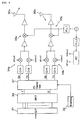
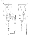
- FIGURE 2 is a block diagram showing the internal configuration of a transmitting device 2b of the transmitting and receiving station 2.
- the transmitting device 2b comprises a serial/parallel (S/P) converting circuit 31, an fd setting circuit 32, an inverse Fourier transform circuit 33, QPSK modulation circuits 34a and 34b, up-converters 35a and 35b and the like.
- S/P serial/parallel
- the inverse Fourier transform circuit 33 realizes various functions as follows.
- the inverse Fourier transform circuit 33 performs inverse Fourier transform on the transmitted data supplied in parallel from the S/P converting circuit 31, converts the inverse Fourier transformed data to return it to serial, and time-compresses a serial symbol string so as to move a posterior symbol to the beginning of the string, thereby setting a guard time.
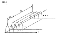
- FIGURE 3 is a graph showing the symbol transmission by OFDM on a frequency axis f and a time axis t.
- An effective symbol length is represented by TS, and a guard time is given by ⁇ t.
- a time compression ratio is represented by (TS + ⁇ t)/TS.
- the transmitting and receiving station 2 and the vehicle-mounted mobile station 4 can avoid intersymbol interference so as to accurately restore the received signal without being adversely affected by the propagation delay due to the presence of a plurality of propagation paths for the radio wave (multipath).
- the QPSK modulation circuits 34a and 34b perform QPSK transform by D/A converting a signal corresponding to the phase 0° and a signal corresponding to the phase 180°, and a signal corresponding to the phase 90° and a signal corresponding to the phase 270° which are output from the inverse Fourier transform circuit 33, subjecting these signals respectively to a sin wave and a cos wave, and adding them.
- QPSK modulation is performed in this embodiment, other modulation methods, for example, QAM, BPSK, 8PSK and the like may be used. In the following description, however, it is assumed that QPSK modulation is performed unless specifically noted.
- the up-converters 35a and 35b are circuits for frequency conversion into a wireless frequency.
- the output signals from the up-converters 35a and 35b pass through a circulator and a coaxial cable to be emitted from road antennas 36a and 36b as radio waves.
- the f d setting circuit 32 is a circuit for setting an offset frequency f d .
- This setting of the offset frequency there are methods of: (1) detecting running speed of a vehicle moving on the road in real time, thereby setting the offset frequency; and (2) previously giving the offset frequency as a constant.
- a method for obtaining average running speed of the vehicles based on the speed information transmitted from each vehicle within the cell there are (1-1) a method for obtaining average running speed of the vehicles based on the speed information transmitted from each vehicle within the cell; (1-2) a method for obtaining average running speed by detecting the speed of each vehicle with an ultrasonic speed sensor or a television camera being arranged on the road; and (1-3) a method for obtaining the average running speed of the vehicles by detecting the speed of each vehicle based on Doppler shift ⁇ f detected on automatic frequency control (AFC) in the receiving device 2a.
- AFC automatic frequency control
- a signal corresponding to the thus set offset frequency + fd is supplied to a voltage control oscillation (VCO) circuit. Then, a signal having an angular frequency of ⁇ + 2 ⁇ fd is generated by a PLL oscillator. After being provided with a phase difference of 90° by a phase-shift circuit, the signal having an angular frequency of ⁇ + 2 ⁇ fd is supplied to the QPSK modulation circuit 34a.
- VCO voltage control oscillation
- a signal corresponding to the offset frequency - fd is supplied to a VCO circuit. Then, a signal having an angular frequency of ⁇ - 2 ⁇ fd is generated by the PLL oscillator. After being provided with a phase difference of 90° by the phase-shift circuit, the signal having an angular frequency of ⁇ - 2 ⁇ fd is supplied to the QPSK modulation circuit 34b.
- a frequency signal having an offset of + fd is obtained from the QPSK modulation circuit 34a while a frequency signal having an offset of - fd is obtained from the QPSK modulation circuit 34b.
- FIGURE 4 is a block diagram showing an exemplary modification of the internal configuration of the transmitting device 2b shown in FIG. 2 .
- the circuit configuration shown in FIG. 4 differs from that shown in FIG. 2 in that a signal I having an in-phase component and a signal Q having an orthogonal component to be input into the QPSK modulation circuit 34 are subjected to frequency correction so as to be provided with offsets while signals having angular frequencies of ⁇ ⁇ 2 ⁇ f d are supplied to a local oscillation circuit of the QPSK modulation circuit 34 so as to be provided with offsets in the circuit configuration of FIG. 2 .
- a circuit for correcting the offset frequency is an f d correction circuit 37.
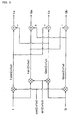
- FIGURE 5 is a circuit diagram showing the internal configuration of the fd correction circuit 37.
- the fd correction circuit 37 produces signals of cos(2 ⁇ fdt) and sin(2 ⁇ fdt) based on the information of the offset frequency fd obtained from the fd setting circuit 32.
- the signal I having an in-phase component and the signal Q having an orthogonal component output from the inverse Fourier transform circuit 33 are respectively multiplied by cos(2 ⁇ fdt) and sin(2 ⁇ fdt) to obtain four signals: I cos 2 ⁇ ⁇ ⁇ f d ⁇ t , I sin 2 ⁇ ⁇ ⁇ f d ⁇ t , Q cos 2 ⁇ ⁇ ⁇ f d ⁇ t , and Q sin 2 ⁇ ⁇ ⁇ f d ⁇ t
- Ia I cos 2 ⁇ ⁇ ⁇ f d ⁇ t - Q sin 2 ⁇ ⁇ ⁇ f d ⁇ t
- Qa Q cos 2 ⁇ ⁇ ⁇ f d ⁇ t + I sin 2 ⁇ ⁇ ⁇ f d ⁇ t
- Ib I cos 2 ⁇ ⁇ ⁇ f d ⁇ t + Q sin 2 ⁇ ⁇ ⁇ f d ⁇ t
- Qb Q cos 2 ⁇ ⁇ ⁇ f d ⁇ - I sin 2 ⁇ ⁇ ⁇ f d ⁇ t
- Ia and Qa are supplied to the QPSK modulation circuit 34a while Ib and Qb are supplied to the QPSK modulation circuit 34b.
- a frequency signal having an offset of + f d is obtained from the QPSK modulation circuit 34a while a frequency signal having an offset of - f d is obtained from the QPSK modulation circuit 34b.
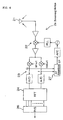
- FIGURE 6 is a block diagram showing the internal configuration of the receiving device 2a of the receiving and transmitting station 2.
- the receiving device 2a comprises a receiving antenna 21, a down-converter 22, a QPSK demodulation circuit 23, a Fourier transform circuit 24, a P/S (parallel/serial) converting circuit 26, a ⁇ f detecting section 27, and the like.
- the down-converter 22 of the receiving device 2a is a circuit which converts a wireless frequency into an intermediate frequency.
- the QPSK demodulation circuit 23 performs QPSK demodulation, wherein one of two divided signals is subjected to a sin wave while the other divided signal is subjected to a cos wave whose phase differs by 90° from that of the sin wave so as to A/D convert these divided signals.
- the frequency difference ⁇ f detecting section 27 detects a deviation ⁇ f of the received frequency based on the in-phase component I (signal after being subjected to a cos wave) and the orthogonal component Q (signal after being subjected to a sin wave) of the QPSK demodulation circuit 23.
- the deviation ⁇ f of the received frequency can be obtained based on a difference between a deflection angle (I/Q) t of a current I/Q and a deflection angle (I/Q) t-1 sampled immediately before I/Q which are obtained by calculating the deflection angle of a complex number I/Q at sampling time intervals.
- ⁇ f I / Q t - I / Q t - 1
- the ⁇ f detecting section 27 feeds back the deviation ⁇ f of the received frequency to the down-converter 22 and the QPSK demodulation circuit 23, thereby accomplishing the function of correcting the deviation ⁇ f of the received frequency.
- the Fourier transform circuit 24 performs processing that is opposite to that of the inverse Fourier transform circuit 33 on the transmission side.
- the Fourier transform circuit 24 performs Fourier transform on the QPSK demodulated signal with the effective symbol length TS as a window length, thereby obtaining a demodulated signal.
- the P/S converting circuit 26 converts a Fourier transformed parallel signal into a serial signal.
- This data converted into a serial signal is transmitted to the central base station 1.
- FIGURE 7 is a conceptual view showing the configuration of a vehicle-mounted mobile station 4.
- the vehicle-mounted mobile station 4 consists of a transmitting and receiving antenna 61, a receiving section, a transmitting section and a frequency control section.
- the transmitting section comprises a S/P converting circuit 47, an inverse Fourier transform circuit 49, a QPSK modulation circuit 50, and an up-converter 51 and the like.
- the receiving section comprises a down-converter 66 for converting a wireless frequency into an intermediate frequency, a QPSK demodulation circuit 63, a Fourier transform circuit 64, a P/S converting circuit 65 and the like. Since the configuration of the receiving part is also well-known and is similar to that of the receiving device 2a described with reference to FIG. 6 , the description thereof is herein omitted.
- the frequency control section has the function of detecting a deviation ⁇ f of the received frequency of the receiving section and the function of performing frequency control of the receiving section based on the deviation ⁇ f.
- deflection angles I/Q of a complex number I/Q are calculated at sample time intervals based on the in-phase component I (signal after being subjected to a cos wave) and the orthogonal component Q (signal after being subjected to a sin wave) of the QPSK demodulation circuit 63.
- the deviation ⁇ f of the received frequency is then detected based on the difference between the deflection angle (I/Q) t of the current I/Q and a deflection angle (I/Q) t-1 sampled immediately before.
- ⁇ f I / Q t - I / Q t - 1
- the frequency control section feeds back the detected deviation ⁇ f of the received frequency to an oscillator of the down-converter 66, thereby accomplishing the function of correcting the deviation ⁇ f of the received frequency.
- f f org - ⁇ f
- f org is a frequency at which oscillation occurs when ⁇ f is 0.
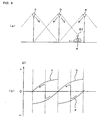
- FIGURE 8 is a graph showing the thus obtained deviations ⁇ f of frequencies.
- FIGURE 8(a) shows the arrangement of road antennas a1, a2; b1, b2; c1 and c2 of a road transmission equipment of the present invention and a vehicle running thereunder.
- a transmitting and receiving antenna hereinafter, simply referred to as a "receiving antenna” 61 and a vehicle-mounted mobile station 4 are mounted.
- FIGURE 8(b) is a graph showing the transitions of the deviations ⁇ f of frequencies.
- the transition of a deviation of the frequency that the receiving antenna 61 receives from the road antenna a2 is indicated by the line a2
- the transition of a deviation of the frequency that the receiving antenna 61 receives from the road antenna b1 is indicated by the line b1
- the transition of a deviation of the frequency that the receiving antenna 61 receives from the road antenna b2 is indicated by the line b2
- the transition of a deviation of the frequency that the receiving antenna 61 receives from the road antenna c1 is indicated by the line c1.
- the deviation ⁇ f of the frequency is reduced to be almost half of that in FIG. 9 owing to the frequency offset fd of the transmitting device 2b on the road.
- the frequency offset fd the Doppler shift to which the vehicle is subjected is halved immediately under the road antennas a1 and a2.
- the skipping of the frequency does not theoretically occur in the case of FIG. 9 , whereas the skipping occurs in the case of FIG. 8 .
- the reason for the occurrence of skipping in the case of FIG. 8 can be explained as follows. Since two antennas, each having a different direction, are provided in a single transmitting and receiving station in the present invention, the received radio waves from these antennas are exchanged when the vehicle passes immediately under the transmitting and receiving station B, thereby causing the skipping of the frequency corresponding to double the amount of the deviation of the offset frequency.
Landscapes
- Engineering & Computer Science (AREA)
- Computer Networks & Wireless Communication (AREA)
- Signal Processing (AREA)
- Mobile Radio Communication Systems (AREA)
- Road Signs Or Road Markings (AREA)
- Geophysics And Detection Of Objects (AREA)
- Radar Systems Or Details Thereof (AREA)
- Reduction Or Emphasis Of Bandwidth Of Signals (AREA)
- Devices For Checking Fares Or Tickets At Control Points (AREA)
Claims (5)
- Straßenübertragungsausrüstung, die für eine Kommunikation zwischen einer Straße und einem Fahrzeug verwendet wird, die zwischen einer in einer Zelle angeordneten Straßenkommunikationsstation und einer Fahrzeug-montierten Mobilstation innerhalb der Zelle kommuniziert, mit:- einer ersten Übertragungsantenne (36a) mit einer Direktivität in einer Laufrichtung eines Fahrzeugs (4),- einer zweiten Übertragungsantenne (36b) mit einer Direktivität in der entgegen gesetzten Richtung zu der Laufrichtung des Fahrzeugs (4),- einem ersten Übertragungsabschnitt und einem zweiten Übertragungsabschnitt, die jeweils mit der ersten Übertragungsantenne und der zweiten Übertragungsantenne verbunden sind, um Signale der gleichen Frequenz auszugeben, und- einem Frequenzkorrekturabschnitt, wobei; der Frequenzkorrekturabschnitt den ersten Übertragungsabschnitt mit einem positiven Frequenzversatz zum Erhöhen der Frequenz eines Signals versorgt, das zu der ersten Übertragungsantenne zugeführt wird und den zweiten Übertragungsabschnitt mit einem negativen Frequenzversatz zum Vermindern der Frequenz eines Signals versorgt, das zu der zweiten Übertragungsantenne zugeführt wird.
- Straßenübertragungsausrüstung nach Anspruch 1, wobei die Beträge des positiven Frequenzversatzes und des negativen Frequenzversatzes, die durch den Frequenzkorrekturabschnitt bereitgestellt werden, zueinander gleich sind.
- Straßenübertragungsausrüstung nach Anspruch 1, weiter mit einer Geschwindigkeitserfassungsvorrichtung zum Erfassen der Geschwindigkeit des Fahrzeugs, das in der Zelle fährt, wobei
der Frequenzkorrekturabschnitt den Betrag des Frequenzversatzes basierend auf der erfassten Geschwindigkeit des Fahrzeugs einstellt. - Straßenübertragungsausrüstung nach Anspruch 1, wobei
der Betrag des Frequenzversatzes, der durch den Frequenzkorrekturabschnitt bereitgestellt wird, auf einen festen Wert auf die Annahme hin eingestellt wird, dass das Fahrzeug einer konstanten Doppler-Verschiebung unterliegt. - Straßenübertragungsausrüstung nach einem der vorangehenden Ansprüche, wobei
jeder des ersten Übertragungsabschnitts und des zweiten Übertragungsabschnitts eine Orthogonal-Frequenzmultiplex-(OFDM)-modulierte Funkwelle überträgt.
Applications Claiming Priority (3)
| Application Number | Priority Date | Filing Date | Title |
|---|---|---|---|
| JP19348599 | 1999-07-07 | ||
| JP19348599A JP3367476B2 (ja) | 1999-07-07 | 1999-07-07 | 路上送信装置 |
| PCT/JP2000/004122 WO2001005065A1 (fr) | 1999-07-07 | 2000-06-22 | Emetteur de bord de route |
Publications (3)
| Publication Number | Publication Date |
|---|---|
| EP1119115A1 EP1119115A1 (de) | 2001-07-25 |
| EP1119115A4 EP1119115A4 (de) | 2004-10-20 |
| EP1119115B1 true EP1119115B1 (de) | 2009-12-30 |
Family
ID=16308827
Family Applications (1)
| Application Number | Title | Priority Date | Filing Date |
|---|---|---|---|
| EP00939137A Expired - Lifetime EP1119115B1 (de) | 1999-07-07 | 2000-06-22 | Sender für strassenseite |
Country Status (8)
| Country | Link |
|---|---|
| US (1) | US6397067B1 (de) |
| EP (1) | EP1119115B1 (de) |
| JP (1) | JP3367476B2 (de) |
| KR (1) | KR20010074982A (de) |
| AT (1) | ATE453971T1 (de) |
| DE (1) | DE60043607D1 (de) |
| IL (2) | IL141700A0 (de) |
| WO (1) | WO2001005065A1 (de) |
Families Citing this family (25)
| Publication number | Priority date | Publication date | Assignee | Title |
|---|---|---|---|---|
| US7120431B1 (en) * | 1999-02-12 | 2006-10-10 | Lucent Technologies Inc. | System and method for adjusting antenna radiation in a wireless network |
| US7952511B1 (en) | 1999-04-07 | 2011-05-31 | Geer James L | Method and apparatus for the detection of objects using electromagnetic wave attenuation patterns |
| JP3782330B2 (ja) * | 2001-09-14 | 2006-06-07 | 富士通株式会社 | Ofdm受信方法及びofdm受信装置 |
| EP1603254A4 (de) * | 2003-02-28 | 2008-04-02 | Nat Inst Inf & Comm Tech | Funkverbindungssystem |
| TWI247490B (en) | 2003-03-25 | 2006-01-11 | Buffalo Inc | Access point |
| US7415243B2 (en) | 2003-03-27 | 2008-08-19 | Honda Giken Kogyo Kabushiki Kaisha | System, method and computer program product for receiving data from a satellite radio network |
| US8041779B2 (en) | 2003-12-15 | 2011-10-18 | Honda Motor Co., Ltd. | Method and system for facilitating the exchange of information between a vehicle and a remote location |
| US7818380B2 (en) | 2003-12-15 | 2010-10-19 | Honda Motor Co., Ltd. | Method and system for broadcasting safety messages to a vehicle |
| EP1733513A4 (de) | 2004-04-06 | 2009-05-06 | Honda Motor Co Ltd | Verfahren und system zur steuerung des austausches von auf ein fahrzeug bezogenen nachrichten |
| US7518530B2 (en) * | 2004-07-19 | 2009-04-14 | Honda Motor Co., Ltd. | Method and system for broadcasting audio and visual display messages to a vehicle |
| US7643788B2 (en) | 2004-09-22 | 2010-01-05 | Honda Motor Co., Ltd. | Method and system for broadcasting data messages to a vehicle |
| US8370054B2 (en) * | 2005-03-24 | 2013-02-05 | Google Inc. | User location driven identification of service vehicles |
| US7562049B2 (en) * | 2005-03-29 | 2009-07-14 | Honda Motor Co., Ltd. | Payment system and method for data broadcasted from a remote location to vehicles |
| US7949330B2 (en) | 2005-08-25 | 2011-05-24 | Honda Motor Co., Ltd. | System and method for providing weather warnings and alerts |
| US8046162B2 (en) * | 2005-11-04 | 2011-10-25 | Honda Motor Co., Ltd. | Data broadcast method for traffic information |
| US20070124306A1 (en) * | 2005-11-09 | 2007-05-31 | Honda Motor Co., Ltd. | Method and system for transmitting data to vehicles over limited data links |
| JP2007194754A (ja) * | 2006-01-18 | 2007-08-02 | Nec Corp | 移動体通信システム及びそれに用いるセル配置方法 |
| JP4892286B2 (ja) * | 2006-06-29 | 2012-03-07 | 京セラ株式会社 | 移動体無線通信装置及び送信周波数制御方法 |
| US7668653B2 (en) | 2007-05-31 | 2010-02-23 | Honda Motor Co., Ltd. | System and method for selectively filtering and providing event program information |
| US8099308B2 (en) | 2007-10-02 | 2012-01-17 | Honda Motor Co., Ltd. | Method and system for vehicle service appointments based on diagnostic trouble codes |
| WO2009110053A1 (ja) * | 2008-03-03 | 2009-09-11 | 富士通株式会社 | 放送サービス信号送信方法及び送信装置 |
| JP5843126B2 (ja) * | 2010-06-30 | 2016-01-13 | 株式会社日立国際電気 | 列車無線通信システム、基地局装置及び無線通信方法 |
| CN103250355B (zh) * | 2010-10-01 | 2015-11-25 | 英派尔科技开发有限公司 | 利用交通数据的基于模型的多普勒补偿方法与系统 |
| CN107370698B (zh) * | 2016-05-13 | 2021-11-30 | 中兴通讯股份有限公司 | 一种下行信号处理方法、装置及基站 |
| US10490074B2 (en) * | 2017-05-09 | 2019-11-26 | Qualcomm Incorporated | Frequency biasing for doppler shift compensation in wireless communications systems |
Family Cites Families (13)
| Publication number | Priority date | Publication date | Assignee | Title |
|---|---|---|---|---|
| JPS57181242A (en) | 1981-04-30 | 1982-11-08 | Hitachi Denshi Ltd | Communication system for moving body |
| DE3508069C2 (de) * | 1985-03-07 | 1993-12-02 | Aeg Mobile Communication | Gleichwellenfunkgerät mit nachgeregelter Senderfrequenz |
| US5168887A (en) | 1990-05-18 | 1992-12-08 | Semitool, Inc. | Single wafer processor apparatus |
| JPH03190331A (ja) | 1989-12-19 | 1991-08-20 | Matsushita Electric Ind Co Ltd | データ受信装置 |
| US5249303A (en) * | 1991-04-23 | 1993-09-28 | Goeken John D | Continuous reception by a mobile receiver unit of program channels transmitted by a series of transmitters |
| DE4222236A1 (de) * | 1992-07-07 | 1994-01-13 | Sel Alcatel Ag | Verfahren und Schaltungsanordnung zur Kompensation einer Dopplerverschiebung |
| JPH08241495A (ja) | 1995-03-02 | 1996-09-17 | Sumitomo Electric Ind Ltd | 安全走行制御システム |
| US5794119A (en) * | 1995-11-21 | 1998-08-11 | Stanford Telecommunications, Inc. | Subscriber frequency control system and method in point-to-multipoint RF communication system |
| US5703595A (en) * | 1996-08-02 | 1997-12-30 | Motorola, Inc. | Method and apparatus for erratic doppler frequency shift compensation |
| JPH10107721A (ja) | 1996-09-27 | 1998-04-24 | Sumitomo Electric Ind Ltd | 車載通信機 |
| US6011515A (en) * | 1996-10-08 | 2000-01-04 | The Johns Hopkins University | System for measuring average speed and traffic volume on a roadway |
| JP3366225B2 (ja) * | 1997-07-09 | 2003-01-14 | 本田技研工業株式会社 | ナビゲーション装置及び車両制御装置 |
| US6091355A (en) * | 1998-07-21 | 2000-07-18 | Speed Products, Inc. | Doppler radar speed measuring unit |
-
1999
- 1999-07-07 JP JP19348599A patent/JP3367476B2/ja not_active Expired - Fee Related
-
2000
- 2000-06-22 WO PCT/JP2000/004122 patent/WO2001005065A1/ja not_active Ceased
- 2000-06-22 DE DE60043607T patent/DE60043607D1/de not_active Expired - Fee Related
- 2000-06-22 EP EP00939137A patent/EP1119115B1/de not_active Expired - Lifetime
- 2000-06-22 IL IL14170000A patent/IL141700A0/xx active IP Right Grant
- 2000-06-22 AT AT00939137T patent/ATE453971T1/de not_active IP Right Cessation
- 2000-06-22 US US09/763,887 patent/US6397067B1/en not_active Expired - Fee Related
- 2000-06-22 KR KR1020017002924A patent/KR20010074982A/ko not_active Withdrawn
-
2001
- 2001-02-27 IL IL141700A patent/IL141700A/en not_active IP Right Cessation
Also Published As
| Publication number | Publication date |
|---|---|
| KR20010074982A (ko) | 2001-08-09 |
| JP2001024576A (ja) | 2001-01-26 |
| US6397067B1 (en) | 2002-05-28 |
| WO2001005065A1 (fr) | 2001-01-18 |
| DE60043607D1 (de) | 2010-02-11 |
| EP1119115A1 (de) | 2001-07-25 |
| EP1119115A4 (de) | 2004-10-20 |
| JP3367476B2 (ja) | 2003-01-14 |
| IL141700A (en) | 2006-12-31 |
| IL141700A0 (en) | 2002-03-10 |
| ATE453971T1 (de) | 2010-01-15 |
Similar Documents
| Publication | Publication Date | Title |
|---|---|---|
| EP1119115B1 (de) | Sender für strassenseite | |
| EP1115221B1 (de) | Kommunikationssystem fahrzeug zu strassenrand, kommunikationsstation am strassenrand, und mobile bordstation | |
| EP1764968B1 (de) | Sende-/Empfangsschaltung mit Vorkompensation von Doppler Verschiebungen | |
| US20040180698A1 (en) | Roadway communication system | |
| CN102210106A (zh) | 移动无线电通信系统、移动通信装置及其频率控制方法 | |
| JP4761845B2 (ja) | 移動体の無線伝送方法、無線伝送装置及び無線伝送システム | |
| EP4408073A1 (de) | Verfahren und vorrichtung zur einstellung des kommunikationsmodus eines endgeräts, endgerät und speichermedium | |
| US6868056B1 (en) | Apparatus and method for OFDM communication | |
| JP2001028576A (ja) | 車載受信装置 | |
| JP3067751B2 (ja) | 路車間通信システム | |
| JP4134410B2 (ja) | 路車間通信システム | |
| JP3008946B2 (ja) | 路車間通信システム | |
| CN101895322A (zh) | 一种信号发送方法及装置 | |
| US10469111B2 (en) | Radio receiver control in high speed scenario | |
| JP5106892B2 (ja) | 移動中継伝送システム | |
| JP2002111576A (ja) | 路車間無線通信システムおよび路車間無線通信で用いられる移動局無線装置 | |
| JP2001016157A (ja) | 路上送信システム及び路上受信システム | |
| JP4719496B2 (ja) | 移動体無線通信システム | |
| JP3289717B2 (ja) | 車両位置検出システム | |
| JPH06167561A (ja) | 現在位置検出用路車間通信システム、現在位置検出用送信装置並びに現在位置検出用受信装置 |
Legal Events
| Date | Code | Title | Description |
|---|---|---|---|
| PUAI | Public reference made under article 153(3) epc to a published international application that has entered the european phase |
Free format text: ORIGINAL CODE: 0009012 |
|
| 17P | Request for examination filed |
Effective date: 20010404 |
|
| AK | Designated contracting states |
Kind code of ref document: A1 Designated state(s): AT BE CH CY DE DK ES FI FR GB GR IE IT LI LU MC NL PT SE |
|
| A4 | Supplementary search report drawn up and despatched |
Effective date: 20040906 |
|
| 17Q | First examination report despatched |
Effective date: 20080221 |
|
| GRAP | Despatch of communication of intention to grant a patent |
Free format text: ORIGINAL CODE: EPIDOSNIGR1 |
|
| GRAS | Grant fee paid |
Free format text: ORIGINAL CODE: EPIDOSNIGR3 |
|
| GRAA | (expected) grant |
Free format text: ORIGINAL CODE: 0009210 |
|
| AK | Designated contracting states |
Kind code of ref document: B1 Designated state(s): AT BE CH CY DE DK ES FI FR GB GR IE IT LI LU MC NL PT SE |
|
| REG | Reference to a national code |
Ref country code: GB Ref legal event code: FG4D |
|
| REG | Reference to a national code |
Ref country code: CH Ref legal event code: EP |
|
| REG | Reference to a national code |
Ref country code: IE Ref legal event code: FG4D |
|
| REF | Corresponds to: |
Ref document number: 60043607 Country of ref document: DE Date of ref document: 20100211 Kind code of ref document: P |
|
| PG25 | Lapsed in a contracting state [announced via postgrant information from national office to epo] |
Ref country code: SE Free format text: LAPSE BECAUSE OF FAILURE TO SUBMIT A TRANSLATION OF THE DESCRIPTION OR TO PAY THE FEE WITHIN THE PRESCRIBED TIME-LIMIT Effective date: 20091230 Ref country code: FI Free format text: LAPSE BECAUSE OF FAILURE TO SUBMIT A TRANSLATION OF THE DESCRIPTION OR TO PAY THE FEE WITHIN THE PRESCRIBED TIME-LIMIT Effective date: 20091230 |
|
| REG | Reference to a national code |
Ref country code: NL Ref legal event code: VDEP Effective date: 20091230 |
|
| PG25 | Lapsed in a contracting state [announced via postgrant information from national office to epo] |
Ref country code: AT Free format text: LAPSE BECAUSE OF FAILURE TO SUBMIT A TRANSLATION OF THE DESCRIPTION OR TO PAY THE FEE WITHIN THE PRESCRIBED TIME-LIMIT Effective date: 20091230 |
|
| PG25 | Lapsed in a contracting state [announced via postgrant information from national office to epo] |
Ref country code: PT Free format text: LAPSE BECAUSE OF FAILURE TO SUBMIT A TRANSLATION OF THE DESCRIPTION OR TO PAY THE FEE WITHIN THE PRESCRIBED TIME-LIMIT Effective date: 20100430 Ref country code: NL Free format text: LAPSE BECAUSE OF FAILURE TO SUBMIT A TRANSLATION OF THE DESCRIPTION OR TO PAY THE FEE WITHIN THE PRESCRIBED TIME-LIMIT Effective date: 20091230 Ref country code: ES Free format text: LAPSE BECAUSE OF FAILURE TO SUBMIT A TRANSLATION OF THE DESCRIPTION OR TO PAY THE FEE WITHIN THE PRESCRIBED TIME-LIMIT Effective date: 20100410 |
|
| PG25 | Lapsed in a contracting state [announced via postgrant information from national office to epo] |
Ref country code: BE Free format text: LAPSE BECAUSE OF FAILURE TO SUBMIT A TRANSLATION OF THE DESCRIPTION OR TO PAY THE FEE WITHIN THE PRESCRIBED TIME-LIMIT Effective date: 20091230 |
|
| PG25 | Lapsed in a contracting state [announced via postgrant information from national office to epo] |
Ref country code: GR Free format text: LAPSE BECAUSE OF FAILURE TO SUBMIT A TRANSLATION OF THE DESCRIPTION OR TO PAY THE FEE WITHIN THE PRESCRIBED TIME-LIMIT Effective date: 20100331 Ref country code: CY Free format text: LAPSE BECAUSE OF FAILURE TO SUBMIT A TRANSLATION OF THE DESCRIPTION OR TO PAY THE FEE WITHIN THE PRESCRIBED TIME-LIMIT Effective date: 20091230 |
|
| PLBE | No opposition filed within time limit |
Free format text: ORIGINAL CODE: 0009261 |
|
| STAA | Information on the status of an ep patent application or granted ep patent |
Free format text: STATUS: NO OPPOSITION FILED WITHIN TIME LIMIT |
|
| 26N | No opposition filed |
Effective date: 20101001 |
|
| PG25 | Lapsed in a contracting state [announced via postgrant information from national office to epo] |
Ref country code: MC Free format text: LAPSE BECAUSE OF NON-PAYMENT OF DUE FEES Effective date: 20100630 Ref country code: DK Free format text: LAPSE BECAUSE OF FAILURE TO SUBMIT A TRANSLATION OF THE DESCRIPTION OR TO PAY THE FEE WITHIN THE PRESCRIBED TIME-LIMIT Effective date: 20091230 |
|
| REG | Reference to a national code |
Ref country code: CH Ref legal event code: PL |
|
| REG | Reference to a national code |
Ref country code: FR Ref legal event code: ST Effective date: 20110228 |
|
| PG25 | Lapsed in a contracting state [announced via postgrant information from national office to epo] |
Ref country code: IT Free format text: LAPSE BECAUSE OF FAILURE TO SUBMIT A TRANSLATION OF THE DESCRIPTION OR TO PAY THE FEE WITHIN THE PRESCRIBED TIME-LIMIT Effective date: 20091230 |
|
| PG25 | Lapsed in a contracting state [announced via postgrant information from national office to epo] |
Ref country code: DE Free format text: LAPSE BECAUSE OF NON-PAYMENT OF DUE FEES Effective date: 20110101 Ref country code: CH Free format text: LAPSE BECAUSE OF NON-PAYMENT OF DUE FEES Effective date: 20100630 Ref country code: LI Free format text: LAPSE BECAUSE OF NON-PAYMENT OF DUE FEES Effective date: 20100630 Ref country code: IE Free format text: LAPSE BECAUSE OF NON-PAYMENT OF DUE FEES Effective date: 20100622 |
|
| PG25 | Lapsed in a contracting state [announced via postgrant information from national office to epo] |
Ref country code: FR Free format text: LAPSE BECAUSE OF NON-PAYMENT OF DUE FEES Effective date: 20100630 |
|
| PGFP | Annual fee paid to national office [announced via postgrant information from national office to epo] |
Ref country code: GB Payment date: 20120620 Year of fee payment: 13 |
|
| PG25 | Lapsed in a contracting state [announced via postgrant information from national office to epo] |
Ref country code: LU Free format text: LAPSE BECAUSE OF NON-PAYMENT OF DUE FEES Effective date: 20100622 |
|
| GBPC | Gb: european patent ceased through non-payment of renewal fee |
Effective date: 20130622 |
|
| PG25 | Lapsed in a contracting state [announced via postgrant information from national office to epo] |
Ref country code: GB Free format text: LAPSE BECAUSE OF NON-PAYMENT OF DUE FEES Effective date: 20130622 |