EP1118800A2 - Steuereinrichtung für ein Getriebe - Google Patents
Steuereinrichtung für ein Getriebe Download PDFInfo
- Publication number
- EP1118800A2 EP1118800A2 EP00123028A EP00123028A EP1118800A2 EP 1118800 A2 EP1118800 A2 EP 1118800A2 EP 00123028 A EP00123028 A EP 00123028A EP 00123028 A EP00123028 A EP 00123028A EP 1118800 A2 EP1118800 A2 EP 1118800A2
- Authority
- EP
- European Patent Office
- Prior art keywords
- housing
- control device
- electrical
- iii
- pressure medium
- Prior art date
- Legal status (The legal status is an assumption and is not a legal conclusion. Google has not performed a legal analysis and makes no representation as to the accuracy of the status listed.)
- Granted
Links
Images


Classifications
-
- F—MECHANICAL ENGINEERING; LIGHTING; HEATING; WEAPONS; BLASTING
- F16—ENGINEERING ELEMENTS AND UNITS; GENERAL MEASURES FOR PRODUCING AND MAINTAINING EFFECTIVE FUNCTIONING OF MACHINES OR INSTALLATIONS; THERMAL INSULATION IN GENERAL
- F16H—GEARING
- F16H61/00—Control functions within control units of change-speed- or reversing-gearings for conveying rotary motion ; Control of exclusively fluid gearing, friction gearing, gearings with endless flexible members or other particular types of gearing
- F16H61/0003—Arrangement or mounting of elements of the control apparatus, e.g. valve assemblies or snapfittings of valves; Arrangements of the control unit on or in the transmission gearbox
- F16H61/0009—Hydraulic control units for transmission control, e.g. assembly of valve plates or valve units
Definitions
- the invention relates to a control device for a transmission according to the preamble of claims 1 and 2.
- Such a control device is from DE 196 37 001 known.
- the known control device for a transmission has several actuating cylinders, one driven by a motor Hydraulic pump, a tank for a hydraulic medium, if necessary a memory for pressurized hydraulic medium and one designed as a proportional control valve Valve device for controlling the actuating cylinders and an electrical control device for actuation the valve device.
- the hydraulic pump with motor as well as the valve device and possibly the memory or the tank are also a hydraulic unit serving unit summarized by the Actuating cylinders and from the electrical control device structurally separated near the gearbox is.
- the invention has for its object a control device to improve the type mentioned at the beginning.
- the embodiment of the invention specified in claim 1 offers in particular the advantage of at least one a part of a pressure supply device, a controllable Valve device and an electrical control device maintain existing compact unit, that is easy to assemble and that with simple Means can be adapted to each transmission.
- controllable valve device By combining the controllable valve device, the pressure supply device and the electrical Control device and possibly also the Actuating cylinders for a structural unit are both the pressure medium connections as well as the electrical connections short.
- electrical connection means and also the pressure medium connection means at least in part located in the housing of the unit. Damage to the electrical connecting means and on the pressure medium connecting means through external influences and possibly impairment of the function caused thereby the controllable valve device, the pump, the motor, the electrical control device and, if necessary also the actuating cylinder are by those mentioned above Measures almost impossible.
- controllable valve device is electromagnetically controlled by several actuated valves formed.
- Fig. 1 is a control device for a Gearbox and clutch shown, one out of two Actuating cylinders for the gearbox existing actuating cylinder assembly (I), a clutch cylinder and one of a Hydraulic unit (II) and an electrical control device (III) existing additional structural unit (II, III) having.
- a first actuating cylinder (4) and a second actuating cylinder (5) are combined to form an actuating cylinder unit (I), e.g. in such a way that in one for both Actuating cylinder (4 and 5) common housing (1) two cylinder bores are provided, being in each of the cylinder bores a piston in the direction of its longitudinal axis is movably arranged.
- a first pressure medium chamber (9) of the first actuating cylinder (4) with one on the housing (1) arranged first pressure medium connection (10) and a second pressure medium chamber (8) of the first Actuating cylinder (4) is arranged on the housing (1) second pressure medium connection (11) connected.
- a first pressure medium chamber (6) of the second actuating cylinder (5) is arranged with a third on the housing (1) Pressure medium connection (12) connected and a second Pressure medium chamber (7) of the second actuating cylinder (5) with a fourth pressure medium connection arranged on the housing (1) (13) connected.
- a hydraulic unit (II) coming from a pressure supply device (43, 44, 42, 45, 46) and a controllable Valve device (22, 23, 24, 25, 26, 27, 28, 29) for controlling the actuating cylinders (4 and 5) and for controlling of the clutch cylinder (31) is with an electric Control device (III) to a further structural unit (II, III) summarized.
- the pressure supply device (43, 44, 42, 45, 46) consists of a pump (43), a motor that drives the pump (43) (44), a pressure accumulator (42) for pressurized Hydraulic medium, a tank (46) for the hydraulic medium and a pressure relief valve (45).
- the Pump (43) and the memory (42) serve as a pressure medium source (43, 42).
- the tank (46) for the hydraulic medium also has the function of a pressure fluid sink.
- the controllable valve device (22, 23, 24, 25, 26, 27, 28, 29) has a first housing part (2), in which a first solenoid valve designed as a 3/2-way valve (22), a 3/2-way valve second solenoid valve (23) and as a 2/2-way valve formed third solenoid valve (26) arranged are.
- a pressure medium inlet of the third solenoid valve (26) is connected via a pressure medium line the pressure medium source (43, 42) and a pressure medium outlet of the third solenoid valve (26) is via pressure medium lines with a pressure medium inlet of the first Solenoid valve (22) and a pressure medium inlet of the second solenoid valve (23).
- the first pressure fluid connection (21) of the first housing part (2) is via a Pressure medium line (20) with the first pressure medium connection (10) of the actuating cylinder assembly (I) connected and the second pressure medium connection (18) of the first housing part (2) stands over a pressure medium line (19) with the second pressure medium connection (11) of the actuating cylinder assembly (I) in connection.
- either the first pressure medium chamber (9) or the second Pressure medium chamber (8) of the first actuating cylinder (4) optionally with the pressure medium source (43, 42) or with the Tank (46) connectable or lockable against both.
- a pressure medium inlet as a 3/2-way valve trained fourth solenoid valve (24) and Pressure medium inlet of the 3/2-way valve fifth solenoid valve (25) are via pressure medium lines with the pressure medium source (43, 42) and a Pressure medium outlet of the fourth solenoid valve (24) and a pressure medium outlet of the fifth solenoid valve (25) are via pressure medium lines with the tank (46) connected.
- a pressure medium outlet of the fourth solenoid valve (24) is via a pressure medium line with a third pressure medium connection (17) of the first Housing part (2) and a pressure medium outlet of the fifth Solenoid valve (25) is via a pressure medium line with a fourth pressure medium connection (14) of the first Housing part (2) connected.
- the third pressure medium connection (17) of the first housing part (2) is over a pressure medium line (16) with the third pressure medium connection (12) the actuating cylinder assembly (I) and the fourth pressure medium connection (14) of the first housing part (2) via a pressure medium line (15) with the fourth pressure medium connection (13) of the actuating cylinder assembly (I) connected.
- the fourth solenoid valve (24) and the fifth solenoid valve (25) is optionally the first Pressure medium chamber (6) or the second pressure medium chamber (7) of the second actuating cylinder (5) optionally with the Pressure medium source (43, 42) or connectable to the tank (46).
- Designed as a 2/2-way valve Eighth solenoid valve (29) is with its pressure medium inlet via a pressure medium line to the with the fifth pressure medium connection (50) of the first housing part (2) connected fluid line and with his Pressure medium outlet via a pressure medium line to the Tank (46) connected.
- the fifth pressure fluid connection (50) of the first housing part (2) is via a pressure medium line (30) connected to the clutch cylinder (31).
- the seventh solenoid valve (28) and the eighth solenoid valve (29) are used to connect the clutch cylinder (31) with the tank (46).
- the electromagnets formed by the solenoid valves controllable valve device (22, 23, 24, 25, 26, 27, 28, 29) are connected via electrical lines (32, 33, 34, 35, 36, 37, 38, 40) with electrical connections one electrical control device (III) electrically connected.
- the motor (44) designed as an electric motor for the pump (43) is connected via an electrical line (39) the electrical control device (III) connected.
- displacement sensors assigned to the actuating cylinders (4, 5) (48, 49) and a pressure sensor (47) via not shown electrical lines with the electrical Control device (III) electrically connected.
- the pressure sensor (47) is arranged in the pressure medium line, which is the pressure medium outlet of the third solenoid valve (26) with the pressure medium inlet of the first solenoid valve (22) and the pressure fluid inlet of the second solenoid valve (23) connects.
- the electrical control device (III) has at least a carrier arranged in a second housing part (3) (41) for electrical and electronic components.
- the carrier (41) can e.g. formed by a circuit board on which electrical and electronic equipment for evaluating the position sensors (48, 49) and the pressure sensor (47) emitted signals and for generating of control signals are arranged.
- the control signals which depend on the signals from the displacement sensors (48, 49) and the pressure sensor (47) and Signals from a gear selector, not shown, are used for controlling the valve device (22, 23, 24, 25, 26, 27, 28, 29).
- the one containing the electrical and electronic components second housing part (3) of the electrical control device (III) is by means of connecting means such as e.g. Screws, clamps, locking or snap connection means, with which the controllable valve device (22, 23, 24, 25, 26, 27, 28, 29), the pressure sensor (47) and optionally the first pressure control valve (45) Housing part (2) connected and forms a housing with this (2, 3) for the controllable valve device (22, 23, 24, 25, 26, 27, 28, 29), the pressure sensor (47) Pressure control valve (45) and the electrical control device (III).
- Electromagnets of the electromagnetic valves (22, 23, 24, 25, 26, 27, 28, 29) and the pressure sensor (47) is preferred with electrical connectors, such as plug pins and sockets.
- the tank (46) and / or the memory (42) or possibly also that Pressure relief valve (45) of the pressure supply device (44, 43, 42, 45, 46) not in or on the housing (2, 3) the controllable valve device (22, 23, 24, 25, 26, 27, 28, 29) and the electrical control device (III) but structurally separated from it on a suitable one Place space near the unit (II, III).
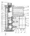
- Fig. 2 shows the first housing part (2) and that as a cover for the first housing part (2) serving second housing part (3), which together the housing (2, 3) for the controllable Valve device (22, 23, 24, 25, 26, 27, 28, 29) and form the electrical control device (III).
- the two Housing parts (2 and 3) are by means of screws trained connecting means (61, 71) connected to each other.
- In the first housing part (2) there is a first step Bore (69) for receiving a valve insert (70) for the first solenoid valve (22) and another stepped bore (67) for receiving a valve insert (68) for the third solenoid valve (26) arranged.
- the mounting holes and inserts for the remaining electromagnetic valves (23, 24, 25, 27, 28, 29) are not shown in FIG. 2.
- the inputs and outputs formed by the inserts (70 and 68) the solenoid valves (22, 26) are not through housing channels shown, which act as pressure medium lines serve with the pressure medium connections assigned to them of the first housing part (2) and partly also with each other connected as shown in Fig.1.
- Another stepped bore (66) in the first housing part (2) is used to hold the pressure sensor (47).
- the solenoid valves (22, 26) sit with one Page on the valve inserts assigned to them (70, 68) and on the bottom of the first housing part (2) on and extend with their other side towards the second housing part (3).
- On the electromagnet of the first Solenoid valve (22) is an electrical connection arranged, which has sockets (52).
- the solenoid of the third solenoid valve also has (26) an electrical connection with sockets (54) and the pressure sensor (47) an electrical connection with sockets (55 and 58), which are Also stretch first in the direction of the second housing part (3).
- the electromagnets are in the same way of the other electromagnetic valves, not shown here (23, 24, 25, 27, 28, 29) with electrical connections provided that have sockets, which are in First stretch towards the second housing part (3).
- first housing part (2) On the side of the first housing part (2) second housing part (3) by means of holding elements (72, 74), e.g. can be designed as screws, a made of an insulating material, e.g. Plastic, existing Carrier (41) for electrical and electronic components (73) of the electrical control device (III) attached.
- the carrier (41) can be designed as a printed circuit board.
- On the carrier (41) are with the electrical and electronic Components connected connector pins (51, 53, 56, 57) arranged so that they are towards the plug sockets (52, 54, 55, 58) stretch first and after joining of the two housing parts (2 and 3) with them assigned sockets (52, 54, 55, 58) one Form electrical plug connection.
- the first housing part (2) faces the second Housing part (3) facing away from one step.
- the Pump (43) and the motor (44) attached and by means of connecting means (64, 65), e.g. B. screws with the first housing part (2) connected.
- the motor (44) has an electrical connection (63, 59) through a Opening in the first housing part (2) into the housing (2, 3) stretched in. Plug sockets (59) of the electrical Connection (63, 59) extend in the direction assigned to them, arranged on the carrier (41) Connector pins (60), of which only one in the drawing is shown and form an electrical with these Connector.
- the controllable valve device arranged in the first housing part (2) (22, 23, 24, 25, 26, 27, 28, 29) thus forms with the pump (43) attached to the first housing part (2), the arranged on the pump (43) and on the first housing part (2) attached motor (44) and in the second housing part (3) arranged electrical control device (III) the further structural unit (II, III).
- the electrical and electronic components as well as the electrical connection means of the electrical control device (III), the controllable valve device (22, 23, 24, 25, 26, 27, 28, 29), the pressure sensor (47) and of the motor (44) are protected in that of the first housing part (2) and limited by the second housing part (3) Room.
- Fig. 3 shows the hydraulic unit (II) and the electrical control device (III) existing unit (II, III), with additional on the structural unit (II, III) the one consisting of the two actuating cylinders Actuating cylinder assembly (I) is arranged.
- first housing part (2) of the housing (2, 3) are by means of the screws serving as connecting means (64, 65) the pump (43) and the motor (44) attached.
- first housing part (2) is from two actuating cylinders (4 and 5) existing actuating cylinder assembly (I) by means of connecting means designed as screws (75, 76) also with the first housing part (2) and thus connected to the housing (2, 3).
- the Pressure medium connections of the actuating cylinders (4, 5) are over Pressure fluid lines, not shown, which also by as Housing channels serving fluid lines in the first Housing part (2) can be formed with the associated Pressure medium outputs of the controllable valve device connected.
- valve device (22, 23, 24, 25, 26, 27, 28, 29) and the pressure supply device (44, 43, 42, 45, 46) formed hydraulic unit (II), the actuating cylinder assembly formed by the actuating cylinders (4, 5) (I) and the electrical control device (III) thus form a structural unit (II, I, III).
- the actuating cylinder (4, 5) not to be combined to form an actuating cylinder assembly, but the actuating cylinders (4, 5) individually on Gearbox or individually on which the controllable valve device (22, 23, 24, 25, 26, 27, 28, 29), the pressure sensor (47) and the electrical control device (III) containing Fasten the housing (2, 3).
- the controllable valve device (22, 23, 24, 25, 26, 27, 28, 29) and possibly part of the pressure supply device (44, 43, 42, 45, 46) can in the first housing part (2) and the electrical device (73) with the carrier (41) can be arranged in the second housing part (3) be, the two housing parts together the Housing (2, 3) from the hydraulic unit (II), the electrical control device (III) and optionally the actuating cylinders (4, 5) existing unit (II, III) or (II, III, 4, 5) form.
- controllable Valve device 22, 23, 24, 25, 26, 27, 28, 29
- the controllable Valve device and possibly a part of the pressure supply device (44, 43, 24, 45, 46) in a first closed Housing and the electrical device (73) with the Arrange the carrier (41) in a second closed housing and these two housings by means of connecting means, such as. Screws to connect together.
- Both Housings have openings through which electrical Leads are passed through to the electrical Connect the in the first closed housing arranged electrical device -Electromagnets of the electromagnetic valves, pressure sensor with the one in the second closed housing arranged electrical device (73) with carrier (41) serve.
- These two together connected housing then form the housing of the the hydraulic unit (II), the electrical control device (III) and optionally the actuating cylinders (4, 5) existing unit (II, III) or (II, III, 4, 5).
- Compressed air can also be used as the pressure medium.
- the pressure supply device from a compressor, a compressed air reservoir and a pressure relief valve.
Landscapes
- Engineering & Computer Science (AREA)
- General Engineering & Computer Science (AREA)
- Mechanical Engineering (AREA)
- Fluid-Pressure Circuits (AREA)
- Gear-Shifting Mechanisms (AREA)
- Hydraulic Clutches, Magnetic Clutches, Fluid Clutches, And Fluid Joints (AREA)
Abstract
Description
- Fig. 1
- schematisch eine aus zwei Stellzylindern bestehende Stellzylinder-Baueinheit und eine aus einer Druckversorgungseinrichtung und einer steuerbaren Ventileinrichtung sowie einer elektrischen Steuereinrichtung bestehende Baueinheit, wobei die steuerbare Ventileinrichtung über Druckmittelleitungen mit den Stellzylindern verbunden ist;
- Fig. 2
- die aus der steuerbaren Ventileinrichtung, der Druckversorgungseinrichtung und der elektrischen Steuereinrichtung bestehende Baueinheit und
- Fig. 3
- eine aus der steuerbaren Ventileinrichtung, der Druckversorgungseinrichtung, der elektrischen Steuereinrichtung und den Stellzylindern bestehende Baueinheit.
Claims (10)
- Steuereinrichtung für ein Getriebe, mit folgenden Merkmalen:dadurch gekennzeichnet, daß die steuerbare Ventileinrichtung (22, 23, 24, 254, 26, 27, 28, 29), wenigstens ein Teil der Druckversorgungseinrichtung (43, 44, 42, 45 46) und die elektrische Steuereinrichtung (III) zu einer Baueinheit zusammengefasst sind.a) es sind mit dem Druck einer Druckversorgungseinrichtung (43, 44, 42, 45, 46) beaufschlagbare Stellzylinder (4, 5) vorgesehen;b es ist eine steuerbare Ventileinrichtung (22, 23, 24, 25, 26, 27, 28, 29) vorgesehen, über welche die Stellzylinder (4, 5) mit der Druckversorgungseinrichtung (43, 44, 42, 45, 46) verbindbar sind;c) es ist eine elektrische Steuereinrichtung (III) zum Ansteuern der steuerbaren Ventileinrichtung (22, 23, 24, 25, 26, 27, 28, 29) vorgesehen;
- Steuereinrichtung für ein Getriebe, mit folgenden Merkmalen:dadurch gekennzeichnet, daß die steuerbare Ventileinrichtung (22, 23, 24, 25, 26, 27, 28, 29), wenigstens ein Teil der Druckversorgungseinrichtung (43, 44, 42, 45, 46), die elektrische Steuereinrichtung (III) und die Stellzylinder (4, 5) zu einer Baueinheit zusammengefasst sind.a) es sind mit dem Druck einer Druckversorgungseinrichtung (43, 44, 42, 45, 46) beaufschlagbare Stellzylinder (4, 5) vorgesehen;b) es ist eine steuerbare Ventileinrichtung (22, 23, 24, 25, 26, 27, 28, 29) vorgesehen, über welche die Stellzylinder (4, 5) mit der Druckversorgungseinrichtung (43, 44, 42, 45, 46) verbindbar sind;c) es ist eine elektrische Steuereinrichtung (III) zum Ansteuern der steuerbaren Ventileinrichtung (22, 23, 24, 25, 26, 27, 28, 29) vorgesehen;
- Steuereinrichtung nach wenigstens einem der vorhergehenden Ansprüche, dadurch gekennzeichnet, daß die Druckversorgungseinrichtung (43, 44, 42, 45, 46) eine Pumpe (43), einen Motor (44) zum Antreiben der Pumpe (43), einen Tank (46) für Hydraulikmedium und gegebenenfalls einen Speicher (42) für unter Druck stehendes Hydraulikmedium aufweist.
- Steuereinrichtung nach wenigstens einem der vorhergehenden Ansprüche, dadurch gekennzeichnet, daß die Druckversorgungseinrichtung aus einem Kompressor und einem Druckluft-Vorratsbehälter besteht.
- Steuereinrichtung nach wenigstens einem der vorhergehenden Ansprüche, gekennzeichnet durch die folgenden Merkmale:a) die aus wenigstens der steuerbaren Ventileinrichtung (22, 23, 24, 25, 26, 27, 28, 29), wenigstens einem Teil der Druckversorgungseinrichtung (43, 44, 42, 45, 46) und der elektrischen Steuereinrichtung (III) bestehende Baueinheit weist ein Gehäuse (2, 3) auf, welches aus einem ersten Gehäuseteil (2) und einem zweiten Gehäuseteil (3) besteht, wobei die beiden Gehäuseteile (2, 3) mittels Verbindungsmitteln (61, 71) miteinander verbunden sind;b) im ersten Gehäuseteil (2) ist die steuerbare Ventileinrichtung (22, 23, 24, 25, 26, 27, 28, 29) angeordnet und im zweiten Gehäuseteil (3) ist die elektrische Steuereinrichtung (III) angeordnet;c) wenigstens die Pumpe (43) und der Motor (44) der Druckversorgungseinrichtung (43, 44, 42, 45, 46) sind am Gehäuse (2, 3) angeordnet und mittels Verbindungsmitteln (64, 65) mit dem Gehäuse (2, 3) verbunden.
- Steuereinrichtung nach wenigstens einem der vorhergehenden Ansprüche, gekennzeichnet durch die folgenden Merkmale:a) die aus wenigstens der steuerbaren Ventileinrichtung (22, 23, 24, 25, 26, 27, 28, 29), wenigstens einem Teil der Druckversorgungseinrichtung (43, 44, 42, 45, 46) und der elektrischen Steuereinrichtung (III) bestehende Baueinheit weist ein erstes Gehäuse und ein zweites Gehäuse auf, wobei die beiden Gehäuse mittels Verbindungsmitteln miteinander verbunden sind;b) im ersten Gehäuse ist die steuerbare Ventileinrichtung (22, 23, 24, 25, 26, 27, 28, 29) angeordnet und im zweiten Gehäuse ist die elektrische Steuereinrichtung (III) angeordnet;c) wenigstens die Pumpe (43) und der Motor (44) der Druckversorgungseinrichtung (43, 44, 42, 45, 46) sind an wenigstens einem der Gehäuse angeordnet und mit wenigstens dem einen Gehäuse mittels Verbindungsmitteln verbunden;d) jedes der beiden Gehäuse weist Öffnungen auf, durch welche elektrische Verbindungsmittel hindurchgeführt sind, die zum Verbinden von im ersten Gehäuse angeordneten elektrischen Einrichtungen mit im zweiten Gehäuse angeordneten elektrischen Einrichtungen dienen.
- Steuereinrichtung nach wenigstens einem der vorhergehenden Ansprüche, dadurch gekennzeichnet, daß der Tank (46) im Gehäuse (2, 3) der Baueinheit oder außen am Gehäuse (2, 3) der Baueinheit angeordnet ist, derart, daß er ein Teil der Baueinheit ist.
- Steuereinrichtung nach wenigstens einem der vorhergehenden Ansprüche, dadurch gekennzeichnet, daß der Speicher (42) im Gehäuse (2, 3) der Baueinheit oder außen am Gehäuse (2, 3) der Baueinheit angeordnet ist, derart, daß er ein Teil der Baueinheit ist.
- Steuereinrichtung nach wenigstens einem der vorhergehenden Ansprüche, dadurch gekennzeichnet, daß die steuerbare Ventileinrichtung (22, 23, 24, 25, 26, 27, 28, 29) aus mehreren Elektromagnetventilen besteht.
- Steuereinrichtung nach wenigstens einem der vorhergehenden Ansprüche, dadurch gekennzeichnet, daß die elektrischen Verbindungsmittel der elektrischen Bauelemente der steuerbaren Ventileinrichtung (22, 23, 24, 25, 26, 27, 28, 29), der elektrischen Bauelemente des wenigstens einen Teiles der Druckversorgungseinrichtung (43, 44, 42, 45, 46) und der elektrischen und elektronischen Bauelemente der elektrischen Steuereinrichtung (III) in einem von den beiden Gehäuseteilen (2, 3) oder in einem von den beiden Gehäusen begrenzten Raum gelegen sind.
Applications Claiming Priority (2)
| Application Number | Priority Date | Filing Date | Title |
|---|---|---|---|
| DE10002693 | 2000-01-22 | ||
| DE10002693A DE10002693A1 (de) | 2000-01-22 | 2000-01-22 | Steuereinrichtung für ein Getriebe |
Publications (3)
| Publication Number | Publication Date |
|---|---|
| EP1118800A2 true EP1118800A2 (de) | 2001-07-25 |
| EP1118800A3 EP1118800A3 (de) | 2005-11-30 |
| EP1118800B1 EP1118800B1 (de) | 2009-04-15 |
Family
ID=7628396
Family Applications (1)
| Application Number | Title | Priority Date | Filing Date |
|---|---|---|---|
| EP00123028A Expired - Lifetime EP1118800B1 (de) | 2000-01-22 | 2000-10-24 | Steuereinrichtung für ein Getriebe |
Country Status (3)
| Country | Link |
|---|---|
| US (1) | US20010009881A1 (de) |
| EP (1) | EP1118800B1 (de) |
| DE (2) | DE10002693A1 (de) |
Cited By (12)
| Publication number | Priority date | Publication date | Assignee | Title |
|---|---|---|---|---|
| EP1515069A2 (de) * | 2003-09-13 | 2005-03-16 | Zf Friedrichshafen Ag | Hydraulische Ansteuerungseinrichtung für ein Getriebe |
| WO2008053048A2 (de) * | 2006-11-04 | 2008-05-08 | Zf Friedrichshafen Ag | Mehrteiliges gehäuse für eine getriebesteuerung und getriebesteuerung mit einem solchen gehäuse |
| CN101761642A (zh) * | 2008-12-11 | 2010-06-30 | 福特环球技术公司 | 变速器油冷却器中流速的控制 |
| EP2381137A1 (de) * | 2010-04-21 | 2011-10-26 | C.R.F. Società Consortile per Azioni | Elektrohydraulische Gruppe für ein servounterstütztes mechanisches Getriebe eines Automobils |
| WO2014170231A1 (de) * | 2013-04-15 | 2014-10-23 | Knorr-Bremse Systeme für Nutzfahrzeuge GmbH | Funktionseinheit zur getriebeschaltung und -steuerung |
| WO2015026411A3 (en) * | 2013-08-22 | 2015-04-23 | Eaton Corporation | Hydraulic control unit having unitary sump and accumulator housing |
| WO2017000939A1 (de) * | 2015-06-30 | 2017-01-05 | Schaeffler Technologies AG & Co. KG | Aktoreinheit für ein fahrzeug |
| USD779560S1 (en) | 2015-07-17 | 2017-02-21 | Eaton Corporation | Hydraulic control unit |
| USD779561S1 (en) | 2015-07-17 | 2017-02-21 | Eaton Corporation | Hydraulic control unit |
| WO2018171837A1 (de) * | 2017-03-22 | 2018-09-27 | Schaeffler Technologies AG & Co. KG | Betätigungsmodul für kupplungen und gangstellersysteme und getriebe mit betätigungsmodul |
| DE102020131056A1 (de) | 2020-11-24 | 2022-05-25 | Schaeffler Technologies AG & Co. KG | Betätigungsmodul und Schaltgetriebe |
| RU2800743C1 (ru) * | 2023-02-21 | 2023-07-27 | Общество с ограниченной ответственностью "Камоцци Пневматика" | Устройство управления коробкой передач в трансмиссии |
Families Citing this family (7)
| Publication number | Priority date | Publication date | Assignee | Title |
|---|---|---|---|---|
| DE10219239A1 (de) * | 2002-04-30 | 2003-11-13 | Zahnradfabrik Friedrichshafen | Schaltbares Getriebe |
| DE102004055030B4 (de) * | 2004-11-15 | 2009-09-10 | Knorr-Bremse Systeme für Nutzfahrzeuge GmbH | Vorrichtung zur Beaufschlagung eines Kolbenstellers mit Druck |
| DE102005028201C5 (de) * | 2005-05-19 | 2009-09-17 | Wilhelm Karmann Gmbh | Betätigungsaggregat |
| US8182238B2 (en) * | 2009-04-03 | 2012-05-22 | Ford Global Technologies, Llc | Variable displacement transmission pump control |
| US8092330B2 (en) * | 2009-09-18 | 2012-01-10 | Ford Global Technologies, Llc | Control for an automatic transmission |
| DE102012210899A1 (de) * | 2012-06-26 | 2014-01-02 | Mahle International Gmbh | Hydraulikfördereinrichtung und Hydrauliksystem |
| DE102014114730B4 (de) | 2014-10-10 | 2021-08-05 | Knorr-Bremse Systeme für Nutzfahrzeuge GmbH | Modulare Steuereinrichtung für ein Schaltgetriebe eines Nutzfahrzeuges |
Citations (4)
| Publication number | Priority date | Publication date | Assignee | Title |
|---|---|---|---|---|
| DE19637001A1 (de) * | 1995-09-12 | 1997-03-13 | Luk Getriebe Systeme Gmbh | Kraftfahrzeug mit einer Einrichtung zur Betätigung des Drehmomentübertragungssystems und des Getriebes |
| EP0877877A1 (de) * | 1996-02-10 | 1998-11-18 | Audi Ag | Steuerungsanordnung für ein automatisches elektrohydraulisch gesteuertes getriebe |
| DE19756639A1 (de) * | 1997-12-19 | 1999-06-24 | Zahnradfabrik Friedrichshafen | Schalteinrichtung |
| EP1177393B1 (de) * | 1999-05-11 | 2003-01-22 | Siemens Aktiengesellschaft | Elektronisch-hydraulische steuereinrichtung für getriebe von fahrzeugen, vorzugsweise von kraftfahrzeugen |
Family Cites Families (2)
| Publication number | Priority date | Publication date | Assignee | Title |
|---|---|---|---|---|
| DE4344584C2 (de) * | 1993-12-24 | 1996-12-12 | Kostal Leopold Gmbh & Co Kg | Anordnung von Magnetventilen, einem Zentralstecker und einer Leiterplatte an einem Steuergehäuse einer selbsttätigen Schaltvorrichtung eines Zahnräderwechselgetriebes |
| NL9401692A (nl) * | 1994-10-13 | 1996-05-01 | Applied Power Inc | Hydraulische bedieningsinrichting en versnellingsbak voorzien van een dergelijke bedieningsinrichting. |
-
2000
- 2000-01-22 DE DE10002693A patent/DE10002693A1/de not_active Ceased
- 2000-10-24 DE DE50015620T patent/DE50015620D1/de not_active Expired - Lifetime
- 2000-10-24 EP EP00123028A patent/EP1118800B1/de not_active Expired - Lifetime
-
2001
- 2001-01-09 US US09/756,963 patent/US20010009881A1/en not_active Abandoned
Patent Citations (4)
| Publication number | Priority date | Publication date | Assignee | Title |
|---|---|---|---|---|
| DE19637001A1 (de) * | 1995-09-12 | 1997-03-13 | Luk Getriebe Systeme Gmbh | Kraftfahrzeug mit einer Einrichtung zur Betätigung des Drehmomentübertragungssystems und des Getriebes |
| EP0877877A1 (de) * | 1996-02-10 | 1998-11-18 | Audi Ag | Steuerungsanordnung für ein automatisches elektrohydraulisch gesteuertes getriebe |
| DE19756639A1 (de) * | 1997-12-19 | 1999-06-24 | Zahnradfabrik Friedrichshafen | Schalteinrichtung |
| EP1177393B1 (de) * | 1999-05-11 | 2003-01-22 | Siemens Aktiengesellschaft | Elektronisch-hydraulische steuereinrichtung für getriebe von fahrzeugen, vorzugsweise von kraftfahrzeugen |
Cited By (24)
| Publication number | Priority date | Publication date | Assignee | Title |
|---|---|---|---|---|
| EP1515069A2 (de) * | 2003-09-13 | 2005-03-16 | Zf Friedrichshafen Ag | Hydraulische Ansteuerungseinrichtung für ein Getriebe |
| EP1515069A3 (de) * | 2003-09-13 | 2009-09-30 | Zf Friedrichshafen Ag | Hydraulische Ansteuerungseinrichtung für ein Getriebe |
| WO2008053048A2 (de) * | 2006-11-04 | 2008-05-08 | Zf Friedrichshafen Ag | Mehrteiliges gehäuse für eine getriebesteuerung und getriebesteuerung mit einem solchen gehäuse |
| WO2008053048A3 (de) * | 2006-11-04 | 2008-06-26 | Zahnradfabrik Friedrichshafen | Mehrteiliges gehäuse für eine getriebesteuerung und getriebesteuerung mit einem solchen gehäuse |
| CN101761642A (zh) * | 2008-12-11 | 2010-06-30 | 福特环球技术公司 | 变速器油冷却器中流速的控制 |
| CN101761642B (zh) * | 2008-12-11 | 2014-05-14 | 福特环球技术公司 | 变速器油冷却器中流速的控制 |
| EP2381137A1 (de) * | 2010-04-21 | 2011-10-26 | C.R.F. Società Consortile per Azioni | Elektrohydraulische Gruppe für ein servounterstütztes mechanisches Getriebe eines Automobils |
| EP2381138A1 (de) * | 2010-04-21 | 2011-10-26 | C.R.F. Società Consortile per Azioni | Elektrohydraulische Gruppe für ein servounterstütztes mechanisches Getriebe eines Automobils |
| WO2011132073A1 (en) * | 2010-04-21 | 2011-10-27 | C.R.F. Società Consortile Per Azioni | Electro-hydraulic actuation group for an automotive servo-assisted mechanical transmission |
| WO2011132072A3 (en) * | 2010-04-21 | 2011-12-22 | C.R.F. Società Consortile Per Azioni | Electro-hydraulic actuation group for an automotive servo- assisted mechanical transmission |
| CN102510962A (zh) * | 2010-04-21 | 2012-06-20 | C.R.F.阿西安尼顾问公司 | 用于车辆伺服辅助机械变速器的电动液压致动组 |
| US9200705B2 (en) | 2010-04-21 | 2015-12-01 | C.R.F. Società Consortile Per Azioni | Electro-hydraulic actuation group for an automotive servo-assisted mechanical transmission |
| US9200706B2 (en) | 2010-04-21 | 2015-12-01 | C.R.F. Societa' Consortile Per Azioni | Electro-hydraulic actuation group for an automotive servo-assisted mechanical transmission |
| CN102510962B (zh) * | 2010-04-21 | 2016-03-02 | C.R.F.阿西安尼顾问公司 | 用于车辆伺服辅助机械变速器的电动液压致动组 |
| WO2014170231A1 (de) * | 2013-04-15 | 2014-10-23 | Knorr-Bremse Systeme für Nutzfahrzeuge GmbH | Funktionseinheit zur getriebeschaltung und -steuerung |
| RU2638063C2 (ru) * | 2013-04-15 | 2017-12-11 | Кнорр-Бремзе Зюстеме Фюр Нутцфарцойге Гмбх | Функциональный блок для переключения коробки передач и управления указанной коробкой передач |
| WO2015026411A3 (en) * | 2013-08-22 | 2015-04-23 | Eaton Corporation | Hydraulic control unit having unitary sump and accumulator housing |
| WO2017000939A1 (de) * | 2015-06-30 | 2017-01-05 | Schaeffler Technologies AG & Co. KG | Aktoreinheit für ein fahrzeug |
| CN107820550A (zh) * | 2015-06-30 | 2018-03-20 | 舍弗勒技术股份两合公司 | 用于交通运输工具的执行单元 |
| USD779560S1 (en) | 2015-07-17 | 2017-02-21 | Eaton Corporation | Hydraulic control unit |
| USD779561S1 (en) | 2015-07-17 | 2017-02-21 | Eaton Corporation | Hydraulic control unit |
| WO2018171837A1 (de) * | 2017-03-22 | 2018-09-27 | Schaeffler Technologies AG & Co. KG | Betätigungsmodul für kupplungen und gangstellersysteme und getriebe mit betätigungsmodul |
| DE102020131056A1 (de) | 2020-11-24 | 2022-05-25 | Schaeffler Technologies AG & Co. KG | Betätigungsmodul und Schaltgetriebe |
| RU2800743C1 (ru) * | 2023-02-21 | 2023-07-27 | Общество с ограниченной ответственностью "Камоцци Пневматика" | Устройство управления коробкой передач в трансмиссии |
Also Published As
| Publication number | Publication date |
|---|---|
| US20010009881A1 (en) | 2001-07-26 |
| DE50015620D1 (de) | 2009-05-28 |
| EP1118800A3 (de) | 2005-11-30 |
| DE10002693A1 (de) | 2001-07-26 |
| EP1118800B1 (de) | 2009-04-15 |
Similar Documents
| Publication | Publication Date | Title |
|---|---|---|
| EP1118800A2 (de) | Steuereinrichtung für ein Getriebe | |
| EP0442033B1 (de) | Ventilbaugruppe | |
| DE60016655T2 (de) | Magnetventilverteilplatte, angetrieben durch seriellen Signale | |
| DE102009060129B4 (de) | Parallele Ventilanordnung | |
| DE102005042102B4 (de) | Zusammenbaustruktur für einen Drucksensor, der einstückig mit einem Elektromagnetischen Ventil ausgebildet ist | |
| EP0391269B1 (de) | Magnetventilbatterie | |
| EP0803653B1 (de) | Pneumatische Betätigungsanordnung | |
| DE19537482A1 (de) | Hydraulischer Steuerblock | |
| DE10216703A1 (de) | Stapelbare Ventilverteileranordnung | |
| DE112008001010T5 (de) | Hybrider Hydraulik-Joystick für elektrisch betätigte Ventile | |
| DE102005005910A1 (de) | Hydraulikcartridgeventil-Magnetspule zum direkten Anbringen an einer Leiterplatte | |
| DE19712211A1 (de) | Elektrohydraulisches Aggregat zur Druckregelung in Bremsanlagen für Kraftfahrzeuge | |
| DE19711227A1 (de) | Plattenartige Montagebasis | |
| DE19547740A1 (de) | Mehrfachventilverteiler | |
| DE10314781A1 (de) | Modulare Kraftstoffeinspritzeinheit | |
| EP0962663B1 (de) | Steuereinricthung für fluidbetätigte Verbraucher | |
| DE102008059348A1 (de) | Stellglieder und Sensoren mit integrierter Elektronik für Automatikgetriebe | |
| DE10259850A1 (de) | Elektromechanische Baugruppe | |
| DE19801234C2 (de) | Ventileinheit | |
| EP0713980B1 (de) | Antriebsvorrichtung | |
| CH683021A5 (de) | Anordnung mit mehreren Magnetventilen, insbesondere für eine Ventilbatterie. | |
| DE10203792B4 (de) | Pneumatische Ventileinheit mit einer parallelen elektrischen Verdrahtung | |
| DE102004044497B3 (de) | Anschlussvorrichtung sowie damit ausgestattetes Ventil und Ventilbatterie | |
| DE102005010297A1 (de) | Elektrohydraulisches Aggregat, insbesondere zur Wankstabilisierung eines Kraftfahrzeuges | |
| DE102010031922A1 (de) | Ventileinheit |
Legal Events
| Date | Code | Title | Description |
|---|---|---|---|
| PUAI | Public reference made under article 153(3) epc to a published international application that has entered the european phase |
Free format text: ORIGINAL CODE: 0009012 |
|
| AK | Designated contracting states |
Kind code of ref document: A2 Designated state(s): AT BE CH CY DE DK ES FI FR GB GR IE IT LI LU MC NL PT SE |
|
| AX | Request for extension of the european patent |
Free format text: AL;LT;LV;MK;RO;SI |
|
| PUAL | Search report despatched |
Free format text: ORIGINAL CODE: 0009013 |
|
| AK | Designated contracting states |
Kind code of ref document: A3 Designated state(s): AT BE CH CY DE DK ES FI FR GB GR IE IT LI LU MC NL PT SE |
|
| AX | Request for extension of the european patent |
Extension state: AL LT LV MK RO SI |
|
| 17P | Request for examination filed |
Effective date: 20060530 |
|
| AKX | Designation fees paid |
Designated state(s): DE FR IT SE |
|
| 17Q | First examination report despatched |
Effective date: 20060915 |
|
| RAP1 | Party data changed (applicant data changed or rights of an application transferred) |
Owner name: WABCO GMBH |
|
| GRAP | Despatch of communication of intention to grant a patent |
Free format text: ORIGINAL CODE: EPIDOSNIGR1 |
|
| GRAS | Grant fee paid |
Free format text: ORIGINAL CODE: EPIDOSNIGR3 |
|
| GRAA | (expected) grant |
Free format text: ORIGINAL CODE: 0009210 |
|
| AK | Designated contracting states |
Kind code of ref document: B1 Designated state(s): DE FR IT SE |
|
| REF | Corresponds to: |
Ref document number: 50015620 Country of ref document: DE Date of ref document: 20090528 Kind code of ref document: P |
|
| REG | Reference to a national code |
Ref country code: SE Ref legal event code: TRGR |
|
| PLBE | No opposition filed within time limit |
Free format text: ORIGINAL CODE: 0009261 |
|
| STAA | Information on the status of an ep patent application or granted ep patent |
Free format text: STATUS: NO OPPOSITION FILED WITHIN TIME LIMIT |
|
| 26N | No opposition filed |
Effective date: 20100118 |
|
| REG | Reference to a national code |
Ref country code: FR Ref legal event code: PLFP Year of fee payment: 16 |
|
| REG | Reference to a national code |
Ref country code: FR Ref legal event code: PLFP Year of fee payment: 17 |
|
| REG | Reference to a national code |
Ref country code: FR Ref legal event code: PLFP Year of fee payment: 18 |
|
| REG | Reference to a national code |
Ref country code: FR Ref legal event code: PLFP Year of fee payment: 19 |
|
| PGFP | Annual fee paid to national office [announced via postgrant information from national office to epo] |
Ref country code: SE Payment date: 20191023 Year of fee payment: 20 Ref country code: DE Payment date: 20191031 Year of fee payment: 20 |
|
| PGFP | Annual fee paid to national office [announced via postgrant information from national office to epo] |
Ref country code: IT Payment date: 20191021 Year of fee payment: 20 Ref country code: FR Payment date: 20191022 Year of fee payment: 20 |
|
| REG | Reference to a national code |
Ref country code: DE Ref legal event code: R071 Ref document number: 50015620 Country of ref document: DE |