EP2381137A1 - Elektrohydraulische Gruppe für ein servounterstütztes mechanisches Getriebe eines Automobils - Google Patents
Elektrohydraulische Gruppe für ein servounterstütztes mechanisches Getriebe eines Automobils Download PDFInfo
- Publication number
- EP2381137A1 EP2381137A1 EP10186531A EP10186531A EP2381137A1 EP 2381137 A1 EP2381137 A1 EP 2381137A1 EP 10186531 A EP10186531 A EP 10186531A EP 10186531 A EP10186531 A EP 10186531A EP 2381137 A1 EP2381137 A1 EP 2381137A1
- Authority
- EP
- European Patent Office
- Prior art keywords
- hydraulic
- electro
- components
- electrical
- actuation group
- Prior art date
- Legal status (The legal status is an assumption and is not a legal conclusion. Google has not performed a legal analysis and makes no representation as to the accuracy of the status listed.)
- Withdrawn
Links
Images


Classifications
-
- F—MECHANICAL ENGINEERING; LIGHTING; HEATING; WEAPONS; BLASTING
- F16—ENGINEERING ELEMENTS AND UNITS; GENERAL MEASURES FOR PRODUCING AND MAINTAINING EFFECTIVE FUNCTIONING OF MACHINES OR INSTALLATIONS; THERMAL INSULATION IN GENERAL
- F16H—GEARING
- F16H61/00—Control functions within control units of change-speed- or reversing-gearings for conveying rotary motion ; Control of exclusively fluid gearing, friction gearing, gearings with endless flexible members or other particular types of gearing
- F16H61/26—Generation or transmission of movements for final actuating mechanisms
- F16H61/28—Generation or transmission of movements for final actuating mechanisms with at least one movement of the final actuating mechanism being caused by a non-mechanical force, e.g. power-assisted
- F16H61/30—Hydraulic or pneumatic motors or related fluid control means therefor
-
- F—MECHANICAL ENGINEERING; LIGHTING; HEATING; WEAPONS; BLASTING
- F16—ENGINEERING ELEMENTS AND UNITS; GENERAL MEASURES FOR PRODUCING AND MAINTAINING EFFECTIVE FUNCTIONING OF MACHINES OR INSTALLATIONS; THERMAL INSULATION IN GENERAL
- F16H—GEARING
- F16H57/00—General details of gearing
- F16H57/02—Gearboxes; Mounting gearing therein
-
- F—MECHANICAL ENGINEERING; LIGHTING; HEATING; WEAPONS; BLASTING
- F16—ENGINEERING ELEMENTS AND UNITS; GENERAL MEASURES FOR PRODUCING AND MAINTAINING EFFECTIVE FUNCTIONING OF MACHINES OR INSTALLATIONS; THERMAL INSULATION IN GENERAL
- F16H—GEARING
- F16H61/00—Control functions within control units of change-speed- or reversing-gearings for conveying rotary motion ; Control of exclusively fluid gearing, friction gearing, gearings with endless flexible members or other particular types of gearing
- F16H61/0003—Arrangement or mounting of elements of the control apparatus, e.g. valve assemblies or snapfittings of valves; Arrangements of the control unit on or in the transmission gearbox
- F16H61/0009—Hydraulic control units for transmission control, e.g. assembly of valve plates or valve units
-
- F—MECHANICAL ENGINEERING; LIGHTING; HEATING; WEAPONS; BLASTING
- F16—ENGINEERING ELEMENTS AND UNITS; GENERAL MEASURES FOR PRODUCING AND MAINTAINING EFFECTIVE FUNCTIONING OF MACHINES OR INSTALLATIONS; THERMAL INSULATION IN GENERAL
- F16H—GEARING
- F16H61/00—Control functions within control units of change-speed- or reversing-gearings for conveying rotary motion ; Control of exclusively fluid gearing, friction gearing, gearings with endless flexible members or other particular types of gearing
- F16H61/0021—Generation or control of line pressure
- F16H61/0025—Supply of control fluid; Pumps therefore
-
- F—MECHANICAL ENGINEERING; LIGHTING; HEATING; WEAPONS; BLASTING
- F16—ENGINEERING ELEMENTS AND UNITS; GENERAL MEASURES FOR PRODUCING AND MAINTAINING EFFECTIVE FUNCTIONING OF MACHINES OR INSTALLATIONS; THERMAL INSULATION IN GENERAL
- F16H—GEARING
- F16H61/00—Control functions within control units of change-speed- or reversing-gearings for conveying rotary motion ; Control of exclusively fluid gearing, friction gearing, gearings with endless flexible members or other particular types of gearing
- F16H61/68—Control functions within control units of change-speed- or reversing-gearings for conveying rotary motion ; Control of exclusively fluid gearing, friction gearing, gearings with endless flexible members or other particular types of gearing specially adapted for stepped gearings
- F16H61/684—Control functions within control units of change-speed- or reversing-gearings for conveying rotary motion ; Control of exclusively fluid gearing, friction gearing, gearings with endless flexible members or other particular types of gearing specially adapted for stepped gearings without interruption of drive
- F16H61/688—Control functions within control units of change-speed- or reversing-gearings for conveying rotary motion ; Control of exclusively fluid gearing, friction gearing, gearings with endless flexible members or other particular types of gearing specially adapted for stepped gearings without interruption of drive with two inputs, e.g. selection of one of two torque-flow paths by clutches
-
- F—MECHANICAL ENGINEERING; LIGHTING; HEATING; WEAPONS; BLASTING
- F16—ENGINEERING ELEMENTS AND UNITS; GENERAL MEASURES FOR PRODUCING AND MAINTAINING EFFECTIVE FUNCTIONING OF MACHINES OR INSTALLATIONS; THERMAL INSULATION IN GENERAL
- F16H—GEARING
- F16H57/00—General details of gearing
- F16H57/02—Gearboxes; Mounting gearing therein
- F16H2057/02026—Connection of auxiliaries with a gear case; Mounting of auxiliaries on the gearbox
-
- F—MECHANICAL ENGINEERING; LIGHTING; HEATING; WEAPONS; BLASTING
- F16—ENGINEERING ELEMENTS AND UNITS; GENERAL MEASURES FOR PRODUCING AND MAINTAINING EFFECTIVE FUNCTIONING OF MACHINES OR INSTALLATIONS; THERMAL INSULATION IN GENERAL
- F16H—GEARING
- F16H61/00—Control functions within control units of change-speed- or reversing-gearings for conveying rotary motion ; Control of exclusively fluid gearing, friction gearing, gearings with endless flexible members or other particular types of gearing
- F16H61/0021—Generation or control of line pressure
- F16H2061/0034—Accumulators for fluid pressure supply; Control thereof
-
- F—MECHANICAL ENGINEERING; LIGHTING; HEATING; WEAPONS; BLASTING
- F16—ENGINEERING ELEMENTS AND UNITS; GENERAL MEASURES FOR PRODUCING AND MAINTAINING EFFECTIVE FUNCTIONING OF MACHINES OR INSTALLATIONS; THERMAL INSULATION IN GENERAL
- F16H—GEARING
- F16H61/00—Control functions within control units of change-speed- or reversing-gearings for conveying rotary motion ; Control of exclusively fluid gearing, friction gearing, gearings with endless flexible members or other particular types of gearing
- F16H61/26—Generation or transmission of movements for final actuating mechanisms
- F16H61/28—Generation or transmission of movements for final actuating mechanisms with at least one movement of the final actuating mechanism being caused by a non-mechanical force, e.g. power-assisted
- F16H61/30—Hydraulic or pneumatic motors or related fluid control means therefor
- F16H2061/308—Modular hydraulic shift units, i.e. preassembled actuator units for select and shift movements adapted for being mounted on transmission casing
-
- Y—GENERAL TAGGING OF NEW TECHNOLOGICAL DEVELOPMENTS; GENERAL TAGGING OF CROSS-SECTIONAL TECHNOLOGIES SPANNING OVER SEVERAL SECTIONS OF THE IPC; TECHNICAL SUBJECTS COVERED BY FORMER USPC CROSS-REFERENCE ART COLLECTIONS [XRACs] AND DIGESTS
- Y10—TECHNICAL SUBJECTS COVERED BY FORMER USPC
- Y10T—TECHNICAL SUBJECTS COVERED BY FORMER US CLASSIFICATION
- Y10T74/00—Machine element or mechanism
- Y10T74/20—Control lever and linkage systems
- Y10T74/20012—Multiple controlled elements
- Y10T74/20018—Transmission control
- Y10T74/20024—Fluid actuator
-
- Y—GENERAL TAGGING OF NEW TECHNOLOGICAL DEVELOPMENTS; GENERAL TAGGING OF CROSS-SECTIONAL TECHNOLOGIES SPANNING OVER SEVERAL SECTIONS OF THE IPC; TECHNICAL SUBJECTS COVERED BY FORMER USPC CROSS-REFERENCE ART COLLECTIONS [XRACs] AND DIGESTS
- Y10—TECHNICAL SUBJECTS COVERED BY FORMER USPC
- Y10T—TECHNICAL SUBJECTS COVERED BY FORMER US CLASSIFICATION
- Y10T74/00—Machine element or mechanism
- Y10T74/21—Elements
- Y10T74/2186—Gear casings
Definitions
- the present invention relates to an electro-hydraulic actuation group for an automotive servo-assisted mechanical transmission.
- the present invention finds particularly advantageous application in the case where the transmission is a dry dual clutch transmission, to which the description that follows will make explicit reference, but without any loss of generality.
- an automotive servo-assisted mechanical transmission comprises a clutch unit, a gearbox with electro-hydraulic actuation and an electro-hydraulic actuation group for operating the clutch unit and for selecting and engaging the gears in the gearbox.
- an electro-hydraulic actuation group of known type can be broken down into three main subgroups: an actuation unit, which is provided with a hydraulic casing housing a hydraulic circuit and supporting a plurality of electrical and hydraulic components, a power unit that is able to supply the necessary hydraulic pressure for operating the actuation unit, and an electronic control unit able to control the actuation and power units.
- the actuation and power units define two distinct assemblies inside the electro-hydraulic actuation group, which are arranged side-by-side and made integral with each other via a connection bracket that is rigidly connected to the hydraulic casing and acts as a support frame for the power unit's components.
- the actuation and power units assembled in this way are normally installed inside a housing outside the gearbox, next to electrical supply connections suitable for supplying the energy needed for operating the power and actuation units.
- the electro-hydraulic actuation groups configured according to the known art described above constitute, up to now, a solution that is not very satisfactory and poorly meets the needs, especially felt in the automotive sector, for cost containment and size reduction.
- electro-hydraulic actuation groups of the above-described type suffer from the drawback of having relatively large bulk, outside of the gearbox, which makes their installation difficult and sometimes problematic.
- these groups require a relatively complex system of connections, both for the hydraulic connection of the power and actuation units to each other and for the electrical connections of the two units to the external power and control connections.
- the object of the present invention is to make an electro-hydraulic actuation group for an automotive servo-assisted mechanical transmission, this group being devoid of the above-described drawbacks.
- an electro-hydraulic actuation group is made for an automotive servo-assisted mechanical transmission according to the attached claims.
- Figure 1 shows the hydraulic diagram of a servo-assisted mechanical transmission 1 for a vehicle (not shown).
- the servo-assisted mechanical transmission 1 can be functionally subdivided into four blocks: a Clutch Unit (CU) block comprising a clutch unit 2, in turn comprising two dry clutches K1 and K2 of known type, a Gear Box (GB) block comprising a mechanical gearbox 3 of known type, and two blocks, a Power Unit (PU) and an Actuation Unit (AU), which together define an electro-hydraulic actuation group 4 for operating the clutch unit 2 and for selecting and engaging gears in the gearbox 3.
- CU Clutch Unit
- GB Gear Box
- PU Power Unit
- AU Actuation Unit
- the AU block comprises an actuation unit 5 and the PU block comprises a power unit 6, which is connected to the actuation unit 5 to provide, during use, the same actuation unit 5 with the hydraulic pressure necessary for its operation.
- the power unit 6 comprises a tank 7 for the oil, a gear pump 8, which is driven by an electric motor 9 and is able to suck oil from the tank 7 through a suction filter 10, and a pressurised oil accumulator 11 connected to the pump 8.
- the actuation unit 5 comprises a hydraulic circuit 12, in turn comprising a feed line 13 that is connected to the delivery side of the pump 8, a distribution line 14 designed to receive oil under pressure from the feed line 13, and a supply line 15 connected to the accumulator 11.
- the supply line 15 also acts as a load line for the accumulator 11 during operation of the pump 8.
- the feed line 13 extends through a feed filter 16 and a non-return valve 17 placed in series and is equipped with a bypass line 18, which is designed to bypass the feed filter 16 in the feed direction of the oil and includes a non-return valve 19.
- the distribution line 14 has five branches able to supply oil under pressure to respective electro-hydraulic valves 20 (of known type), which are part of the actuation unit 5 and, in use, are operated by a transmission control unit (not shown in Figure 1 ) to control the supply of oil under pressure to both the clutch unit 2 and four double-effect pistons 21 (of known type), which are also part of the actuation unit 5 and control gear engagement inside the gearbox 3.
- the five electro-hydraulic valves 20 comprise:
- the hydraulic circuit 12 also comprises a plurality of sensors, including a position sensor 22a for the hydraulic servo-valve 22, a pressure sensor 23 arranged on the distribution line 14, a pressure sensor 24 arranged on an outlet of electro-hydraulic valve 20D associated with clutch K2, and four position sensors 25, each of which is associated with a respective double-effect piston 21.
- the position sensor 22a of the hydraulic servo-valve 22 can be absent and substituted by a predictive control system of the behaviour of the hydraulic servo-valve 22 itself.
- the hydraulic circuit 12 comprises an oil discharge line 26 that runs from the distribution line 14 to the tank 7 and is equipped with a pressure-relief valve 27 set to open when the pressure in the distribution line 14 exceeds a predetermined threshold.
- the discharge line 26 and the tank 7 constitute a single collection system, from which oil is sucked by the pump 8 through the suction filter 10.
- the transmission 1 is electrically controlled by an electronic control unit (ECU), indicated in Figure 1 by reference numeral 49.
- ECU electronice control unit
- the actuation unit 5 and power unit 6 define two distinct assemblies, made integral with each other by means of a connection element.
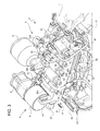
- the actuation unit 5 comprises a generally parallelepipedal hydraulic casing 29 defined by an upper shell 30 and by a lower shell 31 rigidly connected to each other and defining, between them, part of the hydraulic circuit 12.
- the hydraulic casing 29 supports all the other components of the actuation unit 5, some of which are mounted externally on the hydraulic casing 29 and some of which are instead housed in respective seats obtained inside the upper 30 or lower 31 shell.
- the upper shell 30 has an outer surface provided with a longitudinal rib 32, which projects transversally from the above-mentioned outer surface and supports the electro-hydraulic valves 20, arranged side-by-side and evenly set apart from each other.
- the electro-hydraulic valves 20 are housed in respective seats obtained in the upper shell 30 and extend, each one parallel to the other, in a direction of insertion substantially perpendicular to the rib 32.
- Each electro-hydraulic valve 20 is provided with an electrical connector 33 positioned at the free axial end of the respective electro-hydraulic valve 20 and which extends in the above-mentioned direction of insertion.
- the lower shell 31 supports a sensor module 34 housing a plurality of sensors, including position sensors 25, able to measure, in a known manner, respective quantities correlated to the operation of the electro-hydraulic actuation group 4.
- the sensor module 34 is fitted with an electrical connector 35 positioned at one end of the hydraulic casing 29 between the electro-hydraulic valves 20 and the tank 7.
- the position sensor 22a of the hydraulic servo-valve 22 is instead mounted on the side of the rib 32 opposite to the one supporting the electro-hydraulic valves 20 and is provided with an associated electrical connector 22b.
- the pressure sensor 24 associated with clutch K2 is mounted on a longitudinal end of the rib 32 on the opposite side from the electro-hydraulic valves 20 and is provided with an associated connector 36.
- the hydraulic casing 29 also supports the tank 7 and, at the opposite end, the feed filter 16, which comprises a cylindrical outer body having an axis substantially perpendicular to the connecting plane of the upper 30 and lower 31 shells.
- the actuation unit 5 is electrically connected to a control unit (not shown in Figure 2 ) of the transmission 1 by cabling comprising a power line, which provides power to the electrical components of the actuation unit 5, and a signal line, which transmits the signals collected by the actuation unit 5 via its sensors to the control unit.
- the power line comprises a bundle of cables 37 having a watertight electrical input connector 38 and comprising a plurality of cables, fitted at their ends with respective watertight electrical connectors 39 connected to the electrical connectors 33 of the electro-hydraulic valves 20.
- the signal line comprises a bundle of cables 40 having a watertight electrical output connector 41 and comprising a plurality of cables, fitted with respective watertight electrical connectors at their ends and connected to electrical connector 35 of sensor module 34, electrical connector 36 of pressure sensor 24 and electrical connector 22b of position sensor 22a.
- the bundles of cables 37 and 40 are held together by retaining clips 42 so as to form a tidy assembly, at least in part.
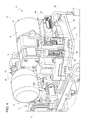
- the power unit 6 is positioned at the side of the actuation unit 5 and comprises a bracket 43 that supports all of the other components of the power unit 6 and is rigidly connected to the hydraulic casing 29 in a position facing the feed filter 16 so as to define the above-mentioned connection element and make the two units integral with each other.
- the accumulator 11 which is connected to the actuation unit 5 via the supply line 15 ( Figure 1 )
- the motor 9 which is fitted with an electrical connector 44 suitable for connecting the motor 9 to an electrical actuator (not shown) normally installed on the vehicle (not shown)
- the pump 8 which is positioned in line with the motor 9 and is connected to the feed filter 16 via a tube that partly defines the feed line 13 ( Figure 1 )
- the suction filter 10 which is placed at the side of the pump 8 and is fluidically connected to the discharge line 26 of the hydraulic circuit 12 via a tube 45 that runs from an inlet of the suction filter 10 to the hydraulic casing 29 and communicates with the discharge line 26 through a hole made in the upper shell 30 on the same side and close to the feed filter 16.
- the discharge line 26 is defined by a channel obtained partly in the upper shell 30 and partly in the lower shell 31 and is positioned along a peripheral portion of the hydraulic casing 29. In this way, since the pressure in the discharge line 26 is close to the ambient pressure, it is possible to avoid sealing problems along the connection portion of the shells, unlike what might occur if the above-mentioned connection portion was instead along a high-pressure channel of the hydraulic circuit 12.
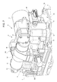
- the electro-hydraulic actuation group 4 shown in Figure 3 mainly differs from the known one shown in Figure 2 in relation to the arrangement of the components of the actuation unit 5 and power unit 6 inside the electro-hydraulic actuation group 4 itself, and in relation to the associated cabling. For this reason and for the sake of clarity, in the description that follows, the same reference numerals will be used, where possible, to indicate parts in Figure 3 that are the same as or correspond to parts in Figure 2 .
- the actuation unit 5 and power unit 6 in the electro-hydraulic actuation group 4 are not two physically distinct assemblies rigidly connected to each other, as in the known example in Figure 2 , but are combined into a single assembly or block, which endows the electro-hydraulic actuation group 4 with compactness and enables the mechanical machining and components needed for the electro-hydraulic connections to be reduced to the minimum.
- the arrangement of the electro-hydraulic valves 20 on the upper shell 30 is substantially identical to that previously described with reference to Figure 2 , while the pump 8, the motor 9, the accumulator 11 and the suction filter 10 are mounted directly on the hydraulic casing 29.
- the accumulator 11 is supported by the upper shell 30 on the part of the rib 32 opposite to that supporting the electro-hydraulic valves 20 and is connected to the distribution line 14 via a channel that defines the supply line 15 and is obtained completely within the hydraulic casing 29, without the need for external piping.
- La pump 8 and the motor 9 are mounted on the rib 32 and are aligned with each other along an axis parallel to the above-mentioned direction of insertion.
- the pump 8 finds itself on the same side as the accumulator 11 with respect to the rib 32
- the motor 9 finds itself on the same side as the electro-hydraulic valves 20;
- the electrical connector 44 of the motor 9 is positioned on a free axial end of the motor 9 and extends in a direction parallel to the above-mentioned direction of insertion.
- the feed filter 16 occupies a position on the hydraulic casing 29 substantially identical to that of the known example in Figure 2 and the pump 8 is placed immediately above the feed filter 16 so as to permit direct connection between an outlet of the pump 8 and an inlet of the feed filter 16, consequently eliminating the need for an external connection pipe.
- the suction filter 10 is mounted on the upper shell 30 at the side of feed filter 16, is parallel to the feed filter 16 and has an outlet that is directly connected to an inlet of the pump 8 and an inlet that tightly engages with an opening obtained in the upper shell 30 and directly facing the discharge line 26.
- the arrangement of the suction filter 10 beneath the pump 8 and in direct fluidic communication with the discharge line 26 has the advantage of not only eliminating the need for an external connection pipe between the suction filter 10 and the hydraulic casing 29, but also of establishing a suction level for the pump 8 capable of guaranteeing the correct operation of the pump 8 itself and eliminating the risk of cavitation phenomena arising.
- pressure sensor 24 is supported by the rib 32 and is positioned, with respect to the rib 32 itself, on the same side as the electro-hydraulic valves 20 and the motor 9, and the associated electrical connector 36, like the electrical connector 44 of the motor 9, extends in a direction parallel to the above-mentioned direction of insertion.
- the rib 32 On opposite sides of the pressure sensor 24, the rib 32 has two communicating openings with respective outlets of two of the electro-hydraulic valves 20 and engaged by respective pipes able, in use, to feed oil under pressure to the hydraulic actuators of the clutches K1 and K2.
- the embodiment shown in Figure 7 differs from that described above only with regard to the shape and arrangement of the accumulator 11 and enables further improvement in the compactness and solidity of the structure.
- the accumulator 11 is defined by a cylindrical body that is cantilever mounted on an appendage 51 projecting from the end of the rib 32 facing the tank 7 and extends parallel to the rib 32 from the part of the rib 32 opposite to the electro-hydraulic valves 20.
- the accumulator 11 is partially wrapped with a retaining band 52 anchored to the rib 32 in a removable manner.
- the components of the actuation unit 5 and power unit 6 are positioned on the hydraulic casing 29 so that the respective electrical connections are all arranged on the same side of the hydraulic casing 29, extending in respective directions parallel to the above-mentioned direction of insertion of the electro-hydraulic valves 20 and are therefore able to all be simultaneously engaged, in a same direction of coupling, by a single connection element.
- the electronic control unit 49 is structurally separate from the assembly formed by the actuation unit 5 and the power unit 6 and is mounted, in a removable manner, on the gearbox 3 in an area away from the hydraulic casing 29 so that it can be easily accessed by an operator for servicing or maintenance without requiring the simultaneous disassembly of the actuation unit 5 and the power unit 6.
- the electrical connector 44 of the motor 9, the electrical connectors 33 of the electro-hydraulic valves 20, the electrical connector 36 of the pressure sensor 24, the electrical connector 35 of the sensor module 34 and, lastly, the electrical connector 22b of the position sensor 22a are connected to the electronic control unit 49 via a multiple electrical connector 46, which simultaneously connects electrical connectors 33, 36, 35 and 22b and has an electrical input/output connector 47 that can be connected to an electrical input/output connector 48 of the electronic control unit 49 via an electrical cable (known and not shown).
- the multiple electrical connector 46 is mounted on the shell 30, extending along the shell 30 itself from the motor 9 up to the tank 7 so as to completely cover the electro-hydraulic valves 20 and comprises a plurality of internal electrical connectors (not visible in the attached figures), each of which is connected to a respective electrical connector of a component of the actuation unit 5 and power unit 6 and is electrically connected to the electrical input/output connector 47 via a respective watertight electrically conductive track 50 (of known type and schematically indicated in Figure 5 with a continuous line) co-printed in the multiple electrical connector 46.
- the above-mentioned internal electrical connectors define an input/output interface for connection of the multiple electrical connector 46 with the electrical components of the electro-hydraulic actuation group 4, and the electrical input/output connector 47 defines an electrical input/output interface for connection of the actuation unit 5 and power unit 6 with the electronic control unit 49.
- the multiple electrical connector 46 is preferable made of a plastic material and is fixed to the upper shell 30 in a removable manner by screws or other fixing devices of known type.
- the multiple electrical connector 46 is suitable for being mounted on the hydraulic casing 29 in a direction of coupling D parallel to the direction of insertion of the electro-hydraulic valves 20, enabling the simultaneous connection of all the electrical connectors arranged on the hydraulic casing 29.
- the multiple electrical connector 46 can be designed to carry out a plurality of functions, based on technical choices and on the possible arrangement of the electronic components needed by the system.
- the multiple electrical connector 46 comprises the above-mentioned electrical connectors (not shown) and the tracks 50, while other electronic components, such as the electrical actuator for piloting the motor 9 (known as a Smart Drive), remain separate from the multiple electrical connector 46; furthermore, in this case, the electronic control unit 49 comprises both the power electronics and the control electronics for piloting the electro-hydraulic valves 20 and the electro-hydraulic valve 22.
- the multiple electrical connector 46 also comprises the electrical actuator for piloting the motor 9 and the power electronics for piloting the electro-hydraulic valves 20, while the electronic control unit 49 comprises just the control electronics; in this case, the electrical input/output connector 47 comprises signal terminals and electric power supply terminals.
Landscapes
- Engineering & Computer Science (AREA)
- General Engineering & Computer Science (AREA)
- Mechanical Engineering (AREA)
- Fluid-Pressure Circuits (AREA)
- Control Of Transmission Device (AREA)
Priority Applications (6)
| Application Number | Priority Date | Filing Date | Title |
|---|---|---|---|
| EP10186531A EP2381137A1 (de) | 2010-04-21 | 2010-10-05 | Elektrohydraulische Gruppe für ein servounterstütztes mechanisches Getriebe eines Automobils |
| BR112012027010-9A BR112012027010B1 (pt) | 2010-04-21 | 2011-04-21 | grupo atuador eletro-hidráulico para uma transmissão mecânica servo assistida automotiva e transmissão mecânica servo assistida automotiva |
| US13/642,171 US9200705B2 (en) | 2010-04-21 | 2011-04-21 | Electro-hydraulic actuation group for an automotive servo-assisted mechanical transmission |
| EP11724749.4A EP2561252B1 (de) | 2010-04-21 | 2011-04-21 | Elektrohydraulische gruppe für ein servounterstütztes mechanisches getriebe eines automobils |
| CN201180002594.4A CN102510962B (zh) | 2010-04-21 | 2011-04-21 | 用于车辆伺服辅助机械变速器的电动液压致动组 |
| PCT/IB2011/000879 WO2011132072A2 (en) | 2010-04-21 | 2011-04-21 | Electro-hydraulic actuation group for an automotive servo- assisted mechanical transmission |
Applications Claiming Priority (2)
| Application Number | Priority Date | Filing Date | Title |
|---|---|---|---|
| EP10425129 | 2010-04-21 | ||
| EP10186531A EP2381137A1 (de) | 2010-04-21 | 2010-10-05 | Elektrohydraulische Gruppe für ein servounterstütztes mechanisches Getriebe eines Automobils |
Publications (2)
| Publication Number | Publication Date |
|---|---|
| EP2381137A1 true EP2381137A1 (de) | 2011-10-26 |
| EP2381137A8 EP2381137A8 (de) | 2012-04-11 |
Family
ID=43858117
Family Applications (4)
| Application Number | Title | Priority Date | Filing Date |
|---|---|---|---|
| EP10186531A Withdrawn EP2381137A1 (de) | 2010-04-21 | 2010-10-05 | Elektrohydraulische Gruppe für ein servounterstütztes mechanisches Getriebe eines Automobils |
| EP10186533A Withdrawn EP2381138A1 (de) | 2010-04-21 | 2010-10-05 | Elektrohydraulische Gruppe für ein servounterstütztes mechanisches Getriebe eines Automobils |
| EP11724749.4A Active EP2561252B1 (de) | 2010-04-21 | 2011-04-21 | Elektrohydraulische gruppe für ein servounterstütztes mechanisches getriebe eines automobils |
| EP11722516.9A Active EP2561251B1 (de) | 2010-04-21 | 2011-04-21 | Elektrohydraulische gruppe für ein servounterstütztes mechanisches getriebe eines automobils |
Family Applications After (3)
| Application Number | Title | Priority Date | Filing Date |
|---|---|---|---|
| EP10186533A Withdrawn EP2381138A1 (de) | 2010-04-21 | 2010-10-05 | Elektrohydraulische Gruppe für ein servounterstütztes mechanisches Getriebe eines Automobils |
| EP11724749.4A Active EP2561252B1 (de) | 2010-04-21 | 2011-04-21 | Elektrohydraulische gruppe für ein servounterstütztes mechanisches getriebe eines automobils |
| EP11722516.9A Active EP2561251B1 (de) | 2010-04-21 | 2011-04-21 | Elektrohydraulische gruppe für ein servounterstütztes mechanisches getriebe eines automobils |
Country Status (5)
| Country | Link |
|---|---|
| US (2) | US9200706B2 (de) |
| EP (4) | EP2381137A1 (de) |
| CN (2) | CN102510962B (de) |
| BR (2) | BR112012027010B1 (de) |
| WO (2) | WO2011132073A1 (de) |
Cited By (6)
| Publication number | Priority date | Publication date | Assignee | Title |
|---|---|---|---|---|
| WO2015010884A1 (de) * | 2013-07-26 | 2015-01-29 | Knorr-Bremse Systeme für Nutzfahrzeuge GmbH | Betätigungseinrichtung für ein schaltgetriebe sowie eine kupplungseinheit eines nutzfahrzeuges |
| WO2017125108A1 (de) * | 2016-01-19 | 2017-07-27 | Schaeffler Technologies AG & Co. KG | Hydraulische schaltanordnung für ein kraftfahrzeug |
| DE102016006751A1 (de) * | 2016-06-06 | 2017-12-07 | Knorr-Bremse Systeme für Nutzfahrzeuge GmbH | Betätigungseinheit für ein Schaltgetriebe eines schaltbaren Antriebsstranges |
| WO2018171837A1 (de) * | 2017-03-22 | 2018-09-27 | Schaeffler Technologies AG & Co. KG | Betätigungsmodul für kupplungen und gangstellersysteme und getriebe mit betätigungsmodul |
| FR3080423A1 (fr) * | 2018-04-18 | 2019-10-25 | Suzuki Motor Corporation | Transmission automatique |
| CN118959551A (zh) * | 2024-10-16 | 2024-11-15 | 坤泰车辆系统(常州)股份有限公司 | 集成式变速箱壳体及加工工艺 |
Families Citing this family (11)
| Publication number | Priority date | Publication date | Assignee | Title |
|---|---|---|---|---|
| US20140165767A1 (en) * | 2012-12-19 | 2014-06-19 | Deere And Company | Manual synchronized gear shift assist |
| EP2787253B1 (de) * | 2013-04-03 | 2018-01-03 | C.R.F. Società Consortile per Azioni | Getriebe für ein Kraftfahrzeug |
| CN103909836A (zh) * | 2014-02-24 | 2014-07-09 | 北京三兴汽车有限公司 | 大功率电容辅助供电动力装置 |
| JP6331993B2 (ja) * | 2014-11-27 | 2018-05-30 | スズキ株式会社 | 自動変速機 |
| DE102015225840A1 (de) * | 2015-12-18 | 2017-06-22 | Robert Bosch Gmbh | Elektrischer Stellantrieb für ein Kraftfahrzeug |
| JP6565946B2 (ja) * | 2017-01-27 | 2019-08-28 | トヨタ自動車株式会社 | 制御部品ユニットの取付構造 |
| WO2019046787A1 (en) * | 2017-09-01 | 2019-03-07 | Eaton Intelligent Power Limited | HYDRAULIC CONTROL UNIT FOR LIMITED SLIP DIFFERENTIAL |
| DE102018102690C5 (de) | 2018-02-07 | 2024-10-24 | Schaeffler Technologies AG & Co. KG | Hydraulische Aktorik |
| DE102018009853B4 (de) * | 2018-12-19 | 2022-12-01 | Fte Automotive Gmbh | Hydraulische Betätigungsvorrichtung für die Betätigung von Stellgliedern in einem Kraftfahrzeuggetriebe |
| DE102019212112A1 (de) * | 2019-08-13 | 2021-02-18 | Zf Friedrichshafen Ag | Dezentraler Steuerblock für ein zentrales hydraulisches Steuergerät eines Kraftfahrzeuggetriebes |
| CN116039915A (zh) * | 2023-01-09 | 2023-05-02 | 中国商用飞机有限责任公司 | 双模式液压伺服作动器 |
Citations (6)
| Publication number | Priority date | Publication date | Assignee | Title |
|---|---|---|---|---|
| DE4237853A1 (de) * | 1992-11-10 | 1994-05-11 | Fichtel & Sachs Ag | Hydraulischer Stellantrieb, insbesondere für eine Kraftfahrzeug-Reibungskupplung |
| FR2703007A1 (fr) * | 1993-03-26 | 1994-09-30 | Fichtel & Sachs Ag | Ensemble de commande hydraulique, notamment pour un embrayage à friction d'un véhicule automobile . |
| US5692909A (en) * | 1996-02-05 | 1997-12-02 | Ford Global Technologies, Inc. | Transmission molded electrical connector system |
| EP1118800A2 (de) * | 2000-01-22 | 2001-07-25 | WABCO GmbH & CO. OHG | Steuereinrichtung für ein Getriebe |
| EP1462681A2 (de) * | 2003-03-28 | 2004-09-29 | Eaton Corporation | Elektro-hydraulische Sammelplatte mit auf einem Leiterrahmen montierten Drucksensoren |
| EP1965101A1 (de) * | 2007-03-01 | 2008-09-03 | CRF Societa'Consortile per Azioni | Elektrohydraulisches Steuersystem für ein Doppelkupplungsgetriebe eines Kraftfahrzeugs |
Family Cites Families (5)
| Publication number | Priority date | Publication date | Assignee | Title |
|---|---|---|---|---|
| BR9304476A (pt) * | 1992-11-10 | 1994-05-17 | Fichtel & Sachs Ag | Acionamento de regulagem hidráulico, especialmente para uma embreagem de atrito de veílculo auto-motor |
| EP1177393B1 (de) * | 1999-05-11 | 2003-01-22 | Siemens Aktiengesellschaft | Elektronisch-hydraulische steuereinrichtung für getriebe von fahrzeugen, vorzugsweise von kraftfahrzeugen |
| US7073407B2 (en) * | 2004-07-09 | 2006-07-11 | Borgwarner Inc. | Integrated control module for use in a dual clutch transmission having integrated shift actuator position sensors |
| US8074680B2 (en) * | 2008-03-28 | 2011-12-13 | Numatics, Incorporated | Modular electrical bus system with built in ground circuit |
| US9033681B2 (en) * | 2009-10-21 | 2015-05-19 | Gm Global Technology Operations, Llc | Control valve body with integrated pump for automatic transmissions |
-
2010
- 2010-10-05 EP EP10186531A patent/EP2381137A1/de not_active Withdrawn
- 2010-10-05 EP EP10186533A patent/EP2381138A1/de not_active Withdrawn
-
2011
- 2011-04-21 BR BR112012027010-9A patent/BR112012027010B1/pt not_active IP Right Cessation
- 2011-04-21 US US13/642,190 patent/US9200706B2/en not_active Expired - Fee Related
- 2011-04-21 WO PCT/IB2011/000880 patent/WO2011132073A1/en active Application Filing
- 2011-04-21 CN CN201180002594.4A patent/CN102510962B/zh not_active Expired - Fee Related
- 2011-04-21 BR BR112012027014A patent/BR112012027014A2/pt active Search and Examination
- 2011-04-21 US US13/642,171 patent/US9200705B2/en not_active Expired - Fee Related
- 2011-04-21 CN CN201180002593.XA patent/CN102510961B/zh not_active Expired - Fee Related
- 2011-04-21 EP EP11724749.4A patent/EP2561252B1/de active Active
- 2011-04-21 EP EP11722516.9A patent/EP2561251B1/de active Active
- 2011-04-21 WO PCT/IB2011/000879 patent/WO2011132072A2/en active Application Filing
Patent Citations (6)
| Publication number | Priority date | Publication date | Assignee | Title |
|---|---|---|---|---|
| DE4237853A1 (de) * | 1992-11-10 | 1994-05-11 | Fichtel & Sachs Ag | Hydraulischer Stellantrieb, insbesondere für eine Kraftfahrzeug-Reibungskupplung |
| FR2703007A1 (fr) * | 1993-03-26 | 1994-09-30 | Fichtel & Sachs Ag | Ensemble de commande hydraulique, notamment pour un embrayage à friction d'un véhicule automobile . |
| US5692909A (en) * | 1996-02-05 | 1997-12-02 | Ford Global Technologies, Inc. | Transmission molded electrical connector system |
| EP1118800A2 (de) * | 2000-01-22 | 2001-07-25 | WABCO GmbH & CO. OHG | Steuereinrichtung für ein Getriebe |
| EP1462681A2 (de) * | 2003-03-28 | 2004-09-29 | Eaton Corporation | Elektro-hydraulische Sammelplatte mit auf einem Leiterrahmen montierten Drucksensoren |
| EP1965101A1 (de) * | 2007-03-01 | 2008-09-03 | CRF Societa'Consortile per Azioni | Elektrohydraulisches Steuersystem für ein Doppelkupplungsgetriebe eines Kraftfahrzeugs |
Cited By (8)
| Publication number | Priority date | Publication date | Assignee | Title |
|---|---|---|---|---|
| WO2015010884A1 (de) * | 2013-07-26 | 2015-01-29 | Knorr-Bremse Systeme für Nutzfahrzeuge GmbH | Betätigungseinrichtung für ein schaltgetriebe sowie eine kupplungseinheit eines nutzfahrzeuges |
| US10161515B2 (en) | 2013-07-26 | 2018-12-25 | Knorr-Bremse Systeme Fuer Nutzfahrzeuge Gmbh | Actuating device for a manual transmission and a clutch unit of a commercial vehicle |
| WO2017125108A1 (de) * | 2016-01-19 | 2017-07-27 | Schaeffler Technologies AG & Co. KG | Hydraulische schaltanordnung für ein kraftfahrzeug |
| US10738884B2 (en) | 2016-01-19 | 2020-08-11 | Schaeffler Technologies AG & Co. KG | Hydraulic switching assembly for a motor vehicle |
| DE102016006751A1 (de) * | 2016-06-06 | 2017-12-07 | Knorr-Bremse Systeme für Nutzfahrzeuge GmbH | Betätigungseinheit für ein Schaltgetriebe eines schaltbaren Antriebsstranges |
| WO2018171837A1 (de) * | 2017-03-22 | 2018-09-27 | Schaeffler Technologies AG & Co. KG | Betätigungsmodul für kupplungen und gangstellersysteme und getriebe mit betätigungsmodul |
| FR3080423A1 (fr) * | 2018-04-18 | 2019-10-25 | Suzuki Motor Corporation | Transmission automatique |
| CN118959551A (zh) * | 2024-10-16 | 2024-11-15 | 坤泰车辆系统(常州)股份有限公司 | 集成式变速箱壳体及加工工艺 |
Also Published As
| Publication number | Publication date |
|---|---|
| EP2561251B1 (de) | 2019-04-17 |
| US9200705B2 (en) | 2015-12-01 |
| CN102510961A (zh) | 2012-06-20 |
| BR112012027014A2 (pt) | 2016-07-19 |
| BR112012027010A2 (pt) | 2016-07-19 |
| WO2011132072A3 (en) | 2011-12-22 |
| WO2011132072A2 (en) | 2011-10-27 |
| BR112012027010B1 (pt) | 2020-11-10 |
| EP2381137A8 (de) | 2012-04-11 |
| EP2381138A1 (de) | 2011-10-26 |
| US20130055706A1 (en) | 2013-03-07 |
| CN102510962B (zh) | 2016-03-02 |
| EP2561251A1 (de) | 2013-02-27 |
| WO2011132073A1 (en) | 2011-10-27 |
| US9200706B2 (en) | 2015-12-01 |
| CN102510961B (zh) | 2015-08-19 |
| EP2561252A2 (de) | 2013-02-27 |
| CN102510962A (zh) | 2012-06-20 |
| US20130055840A1 (en) | 2013-03-07 |
| EP2561252B1 (de) | 2019-06-05 |
Similar Documents
| Publication | Publication Date | Title |
|---|---|---|
| EP2561252B1 (de) | Elektrohydraulische gruppe für ein servounterstütztes mechanisches getriebe eines automobils | |
| CN101725705B (zh) | 双离合变速器集成控制模块 | |
| KR20040084659A (ko) | 압력 센서가 장착된 리드 프레임을 구비한 전기-유압매니폴드 조립체 | |
| CN101194117A (zh) | 自动中间轴变速器及其制造方法 | |
| CN101171445A (zh) | 多组变速器 | |
| JP2003512584A (ja) | 変速機ユニット及び変速機ユニットに用いられる制御プラットフォーム | |
| PL183208B1 (pl) | Urządzenie uruchamiające pneumatyczne | |
| CN104254716A (zh) | 用于车辆变速器的控制器、附加控制器和控制系统以及用于组装车辆变速器的控制系统的方法 | |
| CN101446341B (zh) | 具有集成电子元件的自动变速器致动器和传感器 | |
| CN1952454A (zh) | 安装有压力传感器的电动液压歧管组件 | |
| US5941137A (en) | Controller for a motor vehicle with an automatic transmission | |
| CN101687464A (zh) | 液压驱动车辆 | |
| US20040118466A1 (en) | Electro-hydraulic manifold assembly and pressure sensor therefor | |
| CN102769003A (zh) | 带液体冷却的功率电子装置 | |
| CN105121915A (zh) | 用于切换和控制变速器的功能单元 | |
| KR0157094B1 (ko) | 밸브 레인지 | |
| US20060032541A1 (en) | Electro-hydraulic manifold assembly with mounted pressure sensors | |
| CN103339389B (zh) | 电流体控制装置 | |
| US20210080201A1 (en) | Integrable coolant conveyor module and transmission having coolant conveyor module | |
| CN115585260B (zh) | 一种集成式电控气动换挡执行机构 | |
| KR101274357B1 (ko) | 자동변속기의 전장 하네스 모듈 | |
| CN219796071U (zh) | 换档结构及变速器 | |
| KR101430132B1 (ko) | 차량의 변속기용 에프피씨타입의 배선장치 | |
| CN101435444A (zh) | 液压装置 | |
| CN119177957A (zh) | 一体化电动静液作动装置 |
Legal Events
| Date | Code | Title | Description |
|---|---|---|---|
| AK | Designated contracting states |
Kind code of ref document: A1 Designated state(s): AL AT BE BG CH CY CZ DE DK EE ES FI FR GB GR HR HU IE IS IT LI LT LU LV MC MK MT NL NO PL PT RO RS SE SI SK SM TR |
|
| AX | Request for extension of the european patent |
Extension state: BA ME |
|
| PUAI | Public reference made under article 153(3) epc to a published international application that has entered the european phase |
Free format text: ORIGINAL CODE: 0009012 |
|
| RTI1 | Title (correction) |
Free format text: ELECTRO-HYDRAULIC ACTUATION GROUP FOR AN AUTOMOTIVE SERVO-ASSISTED MECHANICAL TRANSMISSION |
|
| STAA | Information on the status of an ep patent application or granted ep patent |
Free format text: STATUS: THE APPLICATION IS DEEMED TO BE WITHDRAWN |
|
| 18D | Application deemed to be withdrawn |
Effective date: 20120427 |