EP1117883B1 - Autobetonpumpe - Google Patents
Autobetonpumpe Download PDFInfo
- Publication number
- EP1117883B1 EP1117883B1 EP99947351A EP99947351A EP1117883B1 EP 1117883 B1 EP1117883 B1 EP 1117883B1 EP 99947351 A EP99947351 A EP 99947351A EP 99947351 A EP99947351 A EP 99947351A EP 1117883 B1 EP1117883 B1 EP 1117883B1
- Authority
- EP
- European Patent Office
- Prior art keywords
- magazine
- concrete pump
- pump according
- mobile concrete
- vehicle chassis
- Prior art date
- Legal status (The legal status is an assumption and is not a legal conclusion. Google has not performed a legal analysis and makes no representation as to the accuracy of the status listed.)
- Expired - Lifetime
Links
- 230000008878 coupling Effects 0.000 claims description 14
- 238000010168 coupling process Methods 0.000 claims description 14
- 238000005859 coupling reaction Methods 0.000 claims description 14
- 239000000463 material Substances 0.000 claims description 4
- 230000007423 decrease Effects 0.000 claims description 3
- 230000005540 biological transmission Effects 0.000 claims 3
- 230000005484 gravity Effects 0.000 claims 1
- 238000007654 immersion Methods 0.000 description 2
- 238000005192 partition Methods 0.000 description 2
- 241001416181 Axis axis Species 0.000 description 1
- 230000004308 accommodation Effects 0.000 description 1
- 230000001419 dependent effect Effects 0.000 description 1
- 238000011161 development Methods 0.000 description 1
- 230000018109 developmental process Effects 0.000 description 1
- 230000002349 favourable effect Effects 0.000 description 1
- 238000012423 maintenance Methods 0.000 description 1
- 238000000034 method Methods 0.000 description 1
- 238000000926 separation method Methods 0.000 description 1
- 239000002002 slurry Substances 0.000 description 1
- 125000006850 spacer group Chemical group 0.000 description 1
Images





Classifications
-
- B—PERFORMING OPERATIONS; TRANSPORTING
- B28—WORKING CEMENT, CLAY, OR STONE
- B28C—PREPARING CLAY; PRODUCING MIXTURES CONTAINING CLAY OR CEMENTITIOUS MATERIAL, e.g. PLASTER
- B28C5/00—Apparatus or methods for producing mixtures of cement with other substances, e.g. slurries, mortars, porous or fibrous compositions
- B28C5/42—Apparatus specially adapted for being mounted on vehicles with provision for mixing during transport
- B28C5/4203—Details; Accessories
- B28C5/4234—Charge or discharge systems therefor
-
- E—FIXED CONSTRUCTIONS
- E04—BUILDING
- E04G—SCAFFOLDING; FORMS; SHUTTERING; BUILDING IMPLEMENTS OR AIDS, OR THEIR USE; HANDLING BUILDING MATERIALS ON THE SITE; REPAIRING, BREAKING-UP OR OTHER WORK ON EXISTING BUILDINGS
- E04G21/00—Preparing, conveying, or working-up building materials or building elements in situ; Other devices or measures for constructional work
- E04G21/02—Conveying or working-up concrete or similar masses able to be heaped or cast
- E04G21/04—Devices for both conveying and distributing
-
- E—FIXED CONSTRUCTIONS
- E04—BUILDING
- E04G—SCAFFOLDING; FORMS; SHUTTERING; BUILDING IMPLEMENTS OR AIDS, OR THEIR USE; HANDLING BUILDING MATERIALS ON THE SITE; REPAIRING, BREAKING-UP OR OTHER WORK ON EXISTING BUILDINGS
- E04G21/00—Preparing, conveying, or working-up building materials or building elements in situ; Other devices or measures for constructional work
- E04G21/02—Conveying or working-up concrete or similar masses able to be heaped or cast
- E04G21/04—Devices for both conveying and distributing
- E04G21/0418—Devices for both conveying and distributing with distribution hose
- E04G21/0436—Devices for both conveying and distributing with distribution hose on a mobile support, e.g. truck
-
- E—FIXED CONSTRUCTIONS
- E04—BUILDING
- E04G—SCAFFOLDING; FORMS; SHUTTERING; BUILDING IMPLEMENTS OR AIDS, OR THEIR USE; HANDLING BUILDING MATERIALS ON THE SITE; REPAIRING, BREAKING-UP OR OTHER WORK ON EXISTING BUILDINGS
- E04G21/00—Preparing, conveying, or working-up building materials or building elements in situ; Other devices or measures for constructional work
- E04G21/02—Conveying or working-up concrete or similar masses able to be heaped or cast
- E04G21/04—Devices for both conveying and distributing
- E04G21/0418—Devices for both conveying and distributing with distribution hose
- E04G21/0445—Devices for both conveying and distributing with distribution hose with booms
-
- Y—GENERAL TAGGING OF NEW TECHNOLOGICAL DEVELOPMENTS; GENERAL TAGGING OF CROSS-SECTIONAL TECHNOLOGIES SPANNING OVER SEVERAL SECTIONS OF THE IPC; TECHNICAL SUBJECTS COVERED BY FORMER USPC CROSS-REFERENCE ART COLLECTIONS [XRACs] AND DIGESTS
- Y10—TECHNICAL SUBJECTS COVERED BY FORMER USPC
- Y10T—TECHNICAL SUBJECTS COVERED BY FORMER US CLASSIFICATION
- Y10T137/00—Fluid handling
- Y10T137/8593—Systems
- Y10T137/8807—Articulated or swinging flow conduit
Definitions
- the invention relates to a truck-mounted concrete pump with a Chassis that is at least one lateral, parallel to the Has chassis axle extending loading area.
- a Chassis On the Chassis is suitably arranged on a support frame which in turn has a rear material feed container comprehensive pump unit and a fold-out concrete placing boom is arranged, to the pump unit or, if necessary, to the delivery boom conveyor pipes or -Hoses are connectable and being on the support frame preferably laterally next to the one in the driving position Placing boom that has at least one walkable side Loading area is arranged. Because the supporting frame is rigid is connected to the chassis, in the following the Support frame considered as belonging to the chassis.
- truck-mounted concrete pumps of the type specified above such as. in document WO 95/30088 or in particular in the document DE-A-20 21 903 described is the pump unit on the pressure side via a Diverter with a delivery line of the placing boom connectable.
- the pump unit On the pressure side via a Diverter with a delivery line of the placing boom connectable.
- there are applications where immediate to the pump unit in the area of the pipe switch decoupled delivery line of the concrete placing boom separate pipe or hose line is coupled. This is especially the case when the concrete to be concreted Location not reachable with the concrete placing boom is.
- the Truck concrete pump to provide a storage space in which the Pipes and / or hoses can be transported. Proceeding from this, the invention is based on the object Take precautions on a truck-mounted concrete pump that allow the pipes and hoses in the field of Load space easily accessible from the outside and nevertheless keep the loading area accessible.
- an elongated, box-shaped magazine for recording provided by delivery pipes or hoses, that between a transport position spanning the loading area and a removal position releasing the loading area is pivotable or displaceable.
- the magazine is one of the first inventions axis of rotation parallel to the vertical axis of the chassis the cargo area in a transport position Removal position releasing at least part of the loading area pivotable.
- the magazine is an additional transverse to its longitudinal extent and perpendicular to the chassis vertical axis aligned tilt axis from the essentially Transport position aligned parallel to the loading area in one down to its rear end Removable position can be swiveled to a limited extent.
- the transverse axis and the tilt axis expediently form one Type universal joint.
- truck-mounted concrete pumps (DE-A 197 36 108) on the two long sides of the chassis or the support frame each has a rear outrigger to be arranged, which is parallel to the chassis vertical axis Swivel axis between the respective loading area overlapping, aligned parallel to the longitudinal axis of the chassis Transport position in at least one Part of the loading area releasing support position can be swung out is.
- the magazine in a free space above the outrigger is arranged.
- At least one of the magazines can on a chassis that forms the axis of rotation and / or tilting Articulation point are articulated.
- At least one of the magazines can one of the cantilever arms forming the axis of rotation and / or tilting Articulation point are articulated.
- the magazine is there appropriately articulated on the base side at the joint.
- the magazine is advantageously in its transport position can be locked on the support frame or on the outrigger. With outrigger arms and magazines swung out, they are lateral loading areas accessible, so that the pump unit is easily accessible for maintenance purposes, for example.
- a preferred embodiment of the invention provides that the hinge comprises a console that around the to Chassis vertical axis rotatable parallel axis on Transport frame or on the outrigger, while the magazine is pivotable on the Console is arranged. It is an advantage if the tilt axis in the longitudinal extent of the magazine approximately is arranged centrally on the bottom side, the Focus of the magazine in the transport position and in the removal position in its vertical projection different sides of the tilt axis is arranged. In order to is achieved that the magazine in both the horizontal Transport position as well as in the tilted removal position is kept stable by its own weight. additionally can rotate and / or tilt the magazine limited by a limiting element or a stop become.
- a preferred embodiment of the invention provides that between the chassis and magazine preferably as a linkage trained gear means for pivoting of the magazine between the transport position and the untwisted position and tilted end position at a distance from the Rotation and the tilt axis are arranged.
- the gear means are expediently motorized or with hydraulic Means actuable.
- Another alternative embodiment of the invention provides that the elongated box-shaped magazine between a transport position spanning the loading area and a parallel one to the side and / or removal position arranged below the loading area is movable, tiltable or foldable.
- the magazine can be in the transport position on the loading area rest and, if necessary, be locked on the chassis.
- a preferred embodiment of this alternative invention provides that the magazine by means of a four-bar linkage, whose hinge axes parallel to the chassis longitudinal axis are aligned, articulated on the chassis is.
- the coupling gear advantageously has two at one end at a distance from each other on the chassis hinged wings on, with their other end on articulated points of the magazine bottom arranged at a distance from one another are articulated.
- the wings that through the Magazine bottom formed coupling link and that through the articulation points are frame member formed on the chassis Appropriately arranged and dimensioned so that the magazine bottom both in the transport position and in the removal position is aligned parallel to the loading area and in the intermediate positions over the free side edge the loading area swings away without contact.
- a gas pressure spring or a hydraulic cylinder so articulated is that the immersion depth of the spring plunger of the gas pressure spring or the piston rod of the hydraulic cylinder in the associated cylinder on the swivel path between the transport position and the removal position steadily decreases.
- the gas pressure spring is advantageous or the hydraulic cylinder at a pivot point of the shorter, second swing arm articulated above the frame Articulation point is arranged.
- Each of the four-bar linkages can have a gas pressure spring or a hydraulic cylinder with coaxial articulation points be assigned. Basically, however, it is also possible that the two four-bar linkages just a gas spring or a hydraulic cylinder assigned.
- the four-bar linkage can also motorized, for example with the help be driven by a hydraulic motor.
- the magazine in several, aligned parallel to its longitudinal extent, compartments separated by partitions is divided like a honeycomb.
- At least part of the Compartments can be made by pipes, preferably made of plastic, be educated.
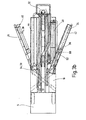
- the truck-mounted concrete pump shown in FIGS. 1 to 4 exists essentially from a multi-axle chassis 10, with a cab 11, one on a near the front axle Mast bracket 12 rotatably mounted about a vertical axis Concrete placing boom 14 and a support structure that a chassis-fixed support frame 16, two on the support frame 16 in 18 diagonally aligned slide-out boxes front outrigger 20 and two to the chassis vertical axis parallel axes 22 pivotable rear Has jib 24.
- the outriggers 20, 24 are each with a downward extending foot section 26 the floor 28 can be supported.
- a two-cylinder slurry pump trained pump unit 30 On the support frame 16 is also a two-cylinder slurry pump trained pump unit 30 arranged, which engages in a material feed container 32 Diverter on the pressure side with conveyor pipes 36 the concrete placing boom 14 is connected.
- the pipe switch 34 can at the separation points 37 from the delivery pipes 36 of the placing boom 14 is uncoupled and independent of it Delivery pipes and / or hoses 38, 40 connected become.
- the conveyor pipes and hoses 38, 40 are in magazines 42, 44, 46 specially provided for this purpose the chassis 10 transported.
- a truck-mounted concrete pump is a manually swiveling one Hose magazine 42, a hydraulically swiveling Hose magazine 44 and one in one of the support legs 24 Integrated tube magazine 46 provided.
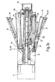
- the elongated Hose magazines 42, 44 are above the side Loading areas 48, 50 of the support frame 16 arranged and around one axis of rotation 52 parallel to the vertical axis of the chassis, 54 from a transport position spanning the loading area (Fig. 3a) in a part of the side loading area 48, 50 releasing removal position (Fig. 3c) pivotable arranged.
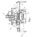
- the magazines are around one transverse to its longitudinal extension and perpendicular to Chassis vertical axis aligned tilt axis 56, 58 of one aligned essentially parallel to the loading surface 48, 50 Transport position in one to the rear End position lowerable lowering position (Fig. 3c, 4) pivotable.
- the axes of rotation 52, 54 form with the associated tilt axes 56, 58 a kind of universal joint.
- the magazines 42, 44 each in a space between the neighboring Outrigger 24 and the placing boom 14 above of the jib 24 arranged.
- the manually swiveling one Magazine 42 has the associated axis of rotation 52 and the articulation point which is fixed to the boom and forms the tilt axis 56 hinged.
- the joint comprises a bracket 60, that on the associated outrigger 24 around the vertical Axis of rotation 52 is arranged pivotably and on which Magazine 42 arranged to pivot limited about the tilt axis 56 is.
- the tilt axis is 56 in the longitudinal extent of the magazine 42 approximately arranged centrally on its bottom side 62, the Focus 64 of the magazine in the horizontal transport position and in the tilted removal position in its vertical projection on different sides of the Tilt axis 56 is arranged (see. Fig. 6a).
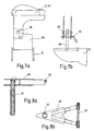
- the magazine 42 In the transport position is the magazine 42 with the locking member 66 a locking device fixed to the jib 68 is pushed on and secured with a plug pin 70.
- the Twist Tilting can be done using suitable stop or spacer elements (not shown) can be limited.
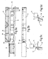
- the hydraulically swiveling magazine 44 is over a the pivot axis 54 and the tilt axis 58 comprising joint hinged directly to the support frame 16. Is further there at a distance from the articulation point 54, 58 nearby a lowering mechanism at the rear end of the chassis 10 72 provided, the trained as an articulated gear Gear means for pivoting the magazine between the transport position (Fig. 5c) and the removal position (Fig. 5d).
- a lowering mechanism at the rear end of the chassis 10 72 provided, the trained as an articulated gear Gear means for pivoting the magazine between the transport position (Fig. 5c) and the removal position (Fig. 5d).
- the piston rod 76 of a hydraulic cylinder 78 articulated via which the lowering mechanism 72 can be operated.
- the magazines are through partitions 80 or plastic pipes 82 divided like a honeycomb, so that one for each hose own subject is available.
- FIGS. 9a to d is a modified one compared to FIGS. 1 to 8 Embodiment of a truck-mounted concrete pump Hose magazines shown. Same parts are with the marked with the same reference numerals. It is missing rear support legs that can be swiveled over the loading area, so that more space for the accommodation of the Hose magazine 142, 144 is available.
- the Hose magazine 142 is rigid on the associated one Loading area 148 arranged while the hose magazine 144 between one overlapping the loading area 150 Transport position and a parallel, laterally removal position arranged next to and below the loading area is movable, tiltable or foldable. In In the transport position, the magazine can be locked on the chassis.
- the movement takes place of the magazine 144 with the help of a four-bar linkage 90, whose hinge axes parallel to Chassis longitudinal axis are aligned.
- the four-bar linkage has two at one end at a distance articulated from one another at articulation points 92, 94 on the chassis Swing 96, 98 on the other end at spaced apart hinge points 100, 102 of the magazine bottom 104 are articulated.
- the wings 96, 98, the coupling member formed by the magazine bottom 104 and that between the fixed articulation points 92, 94 formed frame member 106 are arranged and dimensioned that the magazine bottom 104 both in the transport position as well as parallel in the removal position is aligned to the loading area 150 and in the intermediate positions over the free side edge 108 of the bed swings away without contact.
- the longer swing arm 96 is on the outer corner edge and the shorter rocker 98 hinged to the inside corner edge of the magazine bottom 104, while the frame-side joint 92 of the long Swing arm 96 below the hinge point 94 on the frame side the short rocker 98 is arranged.
- the joint 92 is at Chassis laterally opposite hinge point 94 offset inside so that the short rocker 98 before reaching the transport position with the magazine-side articulation point 102 passes through a higher dead center.
- the four-link linkage is actuated via a hydraulic cylinder 110, the cylinder-side end at a pivot point 112 fixed to the frame and its rod end at one above the fixed one Articulation point 112 arranged articulation point 114 of the short Swing arm 98 is articulated.
- the hydraulic cylinder 110 is like this arranged that the immersion depth of its piston rod 116th in the cylinder 118 on the swing path between the Transport position and the removal position decreases steadily.
- Four-link coupling gear 90 additionally one in Chassis longitudinal direction at a distance from it coaxial four-link coupling gear provided.
- the four-link linkage can either be driven one or two hydraulic cylinders or another motor drive.
- the invention refers to a truck-mounted concrete pump with one on one Chassis 10 arranged support frame 16 and with a arranged on the support frame 16, a rear material feed container 32 comprehensive pump unit 30.
- To the Pump unit 30 are delivery pipes or hoses 38, 40 connectable in magazines 42, 44 with the truck-mounted concrete pump are transportable.
- the magazines are easily accessible, if they are parallel to the chassis vertical axis Axis of rotation 52, 54 and about a transverse to its longitudinal extent and aligned perpendicular to the chassis vertical axis Tilt axis 56, 58 of a substantially parallel to the loading area 48, 50 aligned transport position into one lowered to the rear end Removal position are pivotable.
- the pivoting of the Magazines 42, 44 can either be manual or hydraulic Funds.
Landscapes
- Engineering & Computer Science (AREA)
- Architecture (AREA)
- Mechanical Engineering (AREA)
- Structural Engineering (AREA)
- Civil Engineering (AREA)
- On-Site Construction Work That Accompanies The Preparation And Application Of Concrete (AREA)
- Preparation Of Clay, And Manufacture Of Mixtures Containing Clay Or Cement (AREA)
Description
- Fig. 1
- eine schaubildliche Darstellung einer Autobetonpumpe mit seitlichen Schlauchmagazinen in Transportstellung;
- Fig. 2a
- eine Seitenansicht der Autobetonpumpe mit Sicht auf ein manuell dreh- und senkbares Magazin;
- Fig. 2b
- eine Seitenansicht der Autobetonpumpe von der anderen Seite mit Sicht auf ein hydraulisch schwenk- und senkbares Magazin;
- Fig. 3a
- eine Draufsicht auf die Autobetonpumpe mit Stützauslegern und Magazinen in Transportstellung;
- Fig. 3b
- eine Draufsicht entsprechend Fig. 3a mit ausgeschwenkten rückwärtigen Stützauslegern;
- Fig. 3c
- eine Draufsicht entsprechend Fig. 3b mit Magazinen in Entladestellung;
- Fig. 4
- eine Ansicht der Autobetonpumpe von hinten mit Magazinen in Entladestellung;
- Fig. 5a
- und b eine Seitenansicht und eine Draufsicht des einen Stützauslegers und des hydraulisch schwenkbaren Magazins in Transportstellung;
- Fig. 5c
- und d eine Ansicht. der Senkkinematik des Magazins in angehobener und in abgesenkter Endstellung;
- Fig. 6a
- bis c eine Seitenansicht, eine Stirnseitenansicht und eine Draufsicht des anderen Stützauslegers und des manuell verschwenkbaren Magazins in Transportstellung;
- Fig. 7a
- und b zwei um 90° gegeneinander verdrehte Seitenansichten der Arretierungseinrichtung für das manuell verschwenkbare Magazin;
- Fig. 8a
- und b die Gelenkkonsole für das manuell verschwenkbare Magazin in zwei verschiedenen, teilweise geschnittenen Darstellungen;
- Fig. 9a
- bis d eine Ansicht einer abgewandelten Autobetonpumpe von hinten mit einem schwenkbaren Magazin in verschiedenen Schwenkstellungen.
Claims (31)
- Autobetonpumpe mit einem Fahrgestell (10), das mindestens eine seitliche, parallel zur Fahrgestell-Längsachse verlaufende Ladefläche (48, 50) aufweist,
wobei oberhalb der mindestens einen seitlichen Ladefläche (48, 50) ein langgestrecktes kastenförmiges Magazin (42, 44) zur Aufnahme von Förderrohren oder -schläuchen (38, 40) angeordnet ist, dadurch gekennzeichnet, daß das Magazin (42, 44) um eine zur Fahrgestellhochachse parallele Drehachse (52, 54) von einer die Ladefläche (48, 50) übergreifenden Transportstellung in eine zumindest einen Teil der Ladefläche freigebende Entnahmestellung verschwenkbar ist. - Autobetonpumpe nach Anspruch 1, dadurch gekennzeichnet, daß das Magazin (42, 44) zusätzlich um eine quer zu seiner Längserstreckung und senkrecht zur Fahrgestellhochachse ausgerichtete Kippachse (56, 58) von einer im wesentlichen parallel zur Ladefläche (48, 50) ausgerichteten Transportstellung in eine zu seinem rückwärtigen Ende nach unten begrenzt absenkbare Entnahmestellung verschwenkbar ist.
- Autobetonpumpe nach Anspruch 1 oder 2, dadurch gekennzeichnet, daß die Drehachse (52, 54) und die Kippachse (56, 58) gemeinsam ein Kardangelenk bilden.
- Autobetonpumpe nach einem der Ansprüche 1 bis 3, wobei an den Längsseiten des Fahrgestells (10) je ein um eine zur Fahrgestellhochachse parallele Schwenkachse (22) zwischen einem die jeweilige Ladefläche (48, 50) übergreifenden, parallel zur Fahrgestell-Längsachse ausgerichteten Transportstellung und einer zumindest einen Teil der Ladefläche (48, 50) freigebenden Abstützstellung ausschwenkbarer rückwärtiger Stützausleger (24) angeordnet ist, dadurch gekennzeichnet, daß das Magazin (42, 44) in einem Freiraum oberhalb des Stützauslegers (24) angeordnet ist.
- Autobetonpumpe nach Anspruch 4, dadurch gekennzeichnet, daß zumindest eines der Magazine (44) an einer die Dreh- und/oder Kippachse (54, 58) bildenden, fahrgestellfesten Gelenkstelle angelenkt ist.
- Autobetonpumpe nach Anspruch 4 oder 5, dadurch gekennzeichnet, daß zumindest eines der Magazine (42) an einer die Dreh- und/oder die Kippachse (52, 56) bildenden auslegerfesten Gelenkstelle angelenkt ist.
- Anordnung nach Anspruch 5 oder 6, dadurch gekennzeichnet, daß das Magazin (42, 44) bodenseitig an der Gelenkstelle angelenkt ist.
- Autobetonpumpe nach einem der Ansprüche 1 bis 7, dadurch gekennzeichnet, daß das Magazin (42, 44) in seiner Transportstellung am Fahrgestell (10) oder am Stützausleger (24) arretierbar ist.
- Autobetonpumpe nach einem der Ansprüche 5 bis 8, dadurch gekennzeichnet, daß die Gelenkstelle eine Konsole (60) umfaßt, die um die zur Fahrgestellhochachse parallele Drehachse (52) drehbar am Fahrgestell oder am Stützausleger (24) angeordnet ist, und daß an der Konsole (60) das Magazin (42) um die Kippachse (56) verschwenkbar angeordnet ist.
- Autobetonpumpe nach Anspruch 9, dadurch gekennzeichnet, daß die Kippachse (56) in der Längserstreckung des Magazins (42) etwa mittig an dessen Bodenseite (62) angeordnet ist, wobei der Schwerpunkt (64) des Magazins (42) in der horizontalen Transportstellung und in der abgekippten Entnahmestellung in seiner lotrechten Projektion auf verschiedenen Seiten der Kippachse (56) angeordnet ist.
- Autobetonpumpe nach einem der Ansprüche 1 bis 10, dadurch gekennzeichnet, daß das Magazin (42, 44) durch ein Begrenzungs- oder Anschlagelement um die Drehund/oder Kippachse begrenzt verschwenkbar ist.
- Autobetonpumpe nach einem der Ansprüche 2 bis 11, dadurch gekennzeichnet, daß zwischen Fahrgestell (10) und Magazin (44) vorzugsweise als Gelenkgetriebe ausgebildete Getriebemittel (72) zum Verschwenken des Magazins (44) zwischen der horizontalen Transportstellung und der ausgedrehten und abgekippten Endstellung im Abstand von der zugehörigen Dreh- und der Kippachse (54,58) angeordnet sind.
- Autobetonpumpe nach Anspruch 12, dadurch gekennzeichnet, daß die Getriebemittel (72) mit hydraulischen Mitteln (76, 78) betätigbar sind.
- Autobetonpumpe, mit einem Fahrgestell (10), das mindestens eine seitliche, parallel zur Fahrgestell-Längsachse verlaufende Ladefläche (150) aufweist, und einem langgestreckten kastenförmigen Magazin (144) zur Aufnahme von Förderrohren oder -schläuchen (38), dadurch gekennzeichnet, daß das Magazin (144) zwischen einer die Ladefläche (150) übergreifenden Transportstellung und einer hierzu parallelen, seitlich neben und/oder unterhalb der Ladefläche angeordneten Entnahmestellung bewegbar, kippbar oder herausklappbar ist.
- Autobetonpumpe nach Anspruch 14, dadurch gekennzeichnet, daß das Magazin (144) in der Transportstellung auf der Ladefläche (150) aufliegt.
- Autobetonpumpe nach Anspruch 14 oder 15, dadurch gekennzeichnet, daß das Magazin (144) in der Transportstellung am Fahrgestell (10) arretierbar ist.
- Autobetonpumpe nach einem der Ansprüche 14 bis 16, dadurch gekennzeichnet, daß das Magazin (144) mittels eines Viergelenk-Koppelgetriebes (90), dessen Gelenkachsen parallel zur Fahrgestell-Längsachse ausgerichtet sind, am Fahrgestell (10) angelenkt ist.
- Autobetonpumpe nach Anspruch 17, dadurch gekennzeichnet, daß das Koppelgetriebe (90) zwei an ihrem einen-Ende im Abstand voneinander am Fahrgestell (10) angelenkte Schwingen (96, 98) aufweist, die mit ihrem anderen Ende an im Abstand voneinander angeordneten Gelenkstellen (100, 102) des Magazinbodens (104) angelenkt sind.
- Autobetonpumpe nach Anspruch 18, dadurch gekennzeichnet, daß die Schwingen (96, 98), das durch den Magazinboden (104) gebildete Koppelglied und das durch die Gelenkstellen (92, 94) am Fahrgestell gebildete Gestellglied (106) so angeordnet und bemessen sind, daß der Magazinboden (104) sowohl in der Transportstellung als auch in der Entnahmestellung parallel zur Ladefläche (150) ausgerichtet ist und in den Zwischenstellungen über die freie Seitenkante (108) der Ladefläche (150) berührungsfrei hinwegschwenkt.
- Autobetonpumpe nach Anspruch 18 oder 19, dadurch gekennzeichnet, daß die erste, längere Schwinge (96) an der äußeren Eckkante (100) und die zweite, kürzere Schwinge (98) an der inneren Eckkante (102) des Magazinbodens (104) angelenkt ist, wobei die gestellseitige Gelenkstelle (92) der ersten Schwinge (96) unterhalb der gestellseitigen Gelenkstelle (94) der zweiten Schwinge (98) angeordnet ist.
- Autobetonpumpe nach Anspruch 20, dadurch gekennzeichnet, daß die Gelenkstelle (92) der ersten Schwinge (96) am Fahrgestell (10) seitlich gegenüber der Gelenkstelle (94) der zweiten Schwinge (98) nach innen versetzt ist.
- Autobetonpumpe nach einem der Ansprüche 18 bis 21, dadurch gekennzeichnet, daß zwischen einem gestellfesten Anlenkpunkt (112) und einem Anlenkpunkt (114) einer der beweglichen Schwingen (98) eine Gasdruckfeder oder ein Hydrozylinder (110) so angelenkt ist, daß die Eintauchtiefe des Federstöesels bzw. der Kolbenstange (116) in den zugehörigen Zylinder (118) auf der Schwenkstrecke zwischen der Transportstellung und der Entnahmestellung stetig zu- oder abnimmt.
- Autobetonpumpe nach Anspruch 22, dadurch gekennzeichnet, daß die Gasdruckfeder oder der Hydrozylinder (110) an einer Anlenkstelle (114) der kürzeren, zweiten Schwinge (98) angelenkt ist, die oberhalb der gestellfesten Anlenkstelle (112) angeordnet ist.
- Autobetonpumpe nach einem der Ansprüche 18 bis 23, dadurch gekennzeichnet, daß zwei in Fahrgestell-Längsrichtung im Abstand voneinander angeordnete gleichachsige Viergelenk-Koppelgetriebe (90) vorgesehen sind.
- Autobetonpumpe nach Anspruch 24, dadurch gekennzeichnet, daß jedem der Viergelenk-Koppelgetriebe (90) eine Gasdruckfeder oder ein Hydrozylinder (110) mit gleichachsigen Anlenkstellen (112, 114) zugeordnet ist.
- Autobetonpumpe nach Anspruch 24, dadurch gekennzeichnet, daß den beiden Viergelenk-Koppelgetrieben (90) nur eine Gasdruckfeder oder ein Hydrozylinder (110) zugeordnet ist.
- Autobetonpumpe nach einem der Ansprüche 18 bis 24, dadurch gekennzeichnet, daß das Viergelenk-Koppelgetriebe motorisch antreibbar ist.
- Autobetonpumpe nach einem der Ansprüche 18 bis 27, dadurch gekennzeichnet, daß zumindest eine der Schwingen, vorzugsweise die kurze, zweite Schwinge (98) vor dem Erreichen der Transportstellung mit ihrer magazinseitigen Gelenkstelle (102) einen höher gelegenen Totpunkt durchläuft.
- Autobetonpumpe nach einem der Ansprüche 1 bis 28, dadurch gekennzeichnet, daß das Magazin (42, 44, 144) in mehrere parallel zu seiner Längserstreckung ausgerichtete, durch Zwischenwände (80) voneinander getrennte Fächer (84) unterteilt ist.
- Autobetonpumpe nach Anspruch 29, dadurch gekennzeichnet, daß zumindest ein Teil der Fächer (84) durch Rohre, vorzugsweise aus Kunststoff, gebildet sind.
- Autobetonpumpe nach einem der Ansprüche 1 bis 30, dadurch gekennzeichnet, daß auf dem Fahrgestell (10) ein Tragrahmen (16) angeordnet ist, an welchem eine, einen rückwärtigen Materialaufgabebehälter (32) umfassende Pumpeinheit (30) und ein ausklappbarer Verteilermast (14) angeordnet ist, wobei an die Pumpeinheit (30) oder an den Verteilermast (14) die Förderrohre oder Förderschläuche anschließbar sind und wobei auf dem Tragrahmen seitlich neben dem in Fahrstellung befindlichen Verteilermast (14) mindestens eine der begehbaren seitlichen Ladeflächen (48, 50, 150) angeordnet ist.
Applications Claiming Priority (5)
| Application Number | Priority Date | Filing Date | Title |
|---|---|---|---|
| DE19844341 | 1998-09-28 | ||
| DE19844341 | 1998-09-28 | ||
| DE19850009A DE19850009A1 (de) | 1998-09-28 | 1998-10-30 | Autobetonpumpe |
| DE19850009 | 1998-10-30 | ||
| PCT/EP1999/006816 WO2000019039A1 (de) | 1998-09-28 | 1999-09-15 | Autobetonpumpe |
Publications (2)
| Publication Number | Publication Date |
|---|---|
| EP1117883A1 EP1117883A1 (de) | 2001-07-25 |
| EP1117883B1 true EP1117883B1 (de) | 2003-03-26 |
Family
ID=26049115
Family Applications (1)
| Application Number | Title | Priority Date | Filing Date |
|---|---|---|---|
| EP99947351A Expired - Lifetime EP1117883B1 (de) | 1998-09-28 | 1999-09-15 | Autobetonpumpe |
Country Status (4)
| Country | Link |
|---|---|
| US (1) | US6484752B1 (de) |
| EP (1) | EP1117883B1 (de) |
| ES (1) | ES2193748T3 (de) |
| WO (1) | WO2000019039A1 (de) |
Cited By (1)
| Publication number | Priority date | Publication date | Assignee | Title |
|---|---|---|---|---|
| EP4387869A1 (de) * | 2021-08-16 | 2024-06-26 | Putzmeister Engineering GmbH | Rahmengestell einer mobilen arbeitsmaschine mit einem transportmagazin |
Families Citing this family (19)
| Publication number | Priority date | Publication date | Assignee | Title |
|---|---|---|---|---|
| DE10000814A1 (de) * | 2000-01-12 | 2001-07-19 | Putzmeister Ag | Fahrbare Betonpumpe mit teleskopierbaren Stützauslegern |
| DE10032622A1 (de) * | 2000-07-07 | 2002-01-17 | Putzmeister Ag | Stützausleger für fahrbare Arbeitsmaschinen und Autobetonpumpen mit solchen Stützauslegern |
| ITMI20050434A1 (it) * | 2005-03-17 | 2006-09-18 | Stefano Baiardo | Dispositivo estensibile per la distribuzione di calcestruzzo |
| US7513758B2 (en) * | 2005-11-08 | 2009-04-07 | Good Earth Tools, Inc. | Sealing rings for abrasive slurry pumps |
| DE102005055667B4 (de) * | 2005-11-22 | 2009-02-12 | Schwing Gmbh | Knickmast für eine Dickstoffförderanlage |
| DE102008007918A1 (de) * | 2008-02-06 | 2009-08-13 | Putzmeister Concrete Pumps Gmbh | Fahrbare Arbeitsmaschine |
| CN102039877B (zh) * | 2010-09-25 | 2012-06-27 | 中联重科股份有限公司 | 支腿结构、混凝土泵车及油管装配方法 |
| US20130043714A1 (en) * | 2011-08-19 | 2013-02-21 | Raphael Schlanger | Vehicle wheel spoke connection |
| DE102012215050A1 (de) * | 2012-08-24 | 2014-03-27 | Putzmeister Engineering Gmbh | Fahrbare Betonpumpe |
| CN103707794A (zh) * | 2013-12-05 | 2014-04-09 | 亚太水处理(天长)有限公司 | 一种液压式移动泵车 |
| CN104265730B (zh) * | 2014-10-21 | 2017-01-18 | 安徽星马专用汽车有限公司 | 一种臂架液压缸及臂架式混凝土泵车 |
| USD788883S1 (en) | 2015-04-16 | 2017-06-06 | Robert A Drake | Pressure relief valve for use with concrete pumping system |
| US9732739B2 (en) | 2015-04-16 | 2017-08-15 | Robert A Drake | Concrete pumping system having safety recirculation and method features |
| CN108909586A (zh) * | 2018-06-28 | 2018-11-30 | 福建侨龙应急装备有限公司 | 一种双折叠履带式排水车 |
| CN108909587A (zh) * | 2018-06-29 | 2018-11-30 | 福建侨龙应急装备有限公司 | 一种双折叠式排水车 |
| CN110549489B (zh) * | 2019-09-19 | 2024-08-09 | 长沙爱达智能科技有限公司 | 一种混凝土搅拌站集料斗 |
| CN111058637B (zh) * | 2019-11-26 | 2021-08-31 | 上海建工集团股份有限公司 | 横折臂混凝土布料机的智能布料控制系统及方法 |
| CN115262557B (zh) * | 2022-05-23 | 2024-05-28 | 福建士维建设有限公司 | 一种水利堤防工程施工用混凝土浇筑设备 |
| DE102024114106A1 (de) * | 2024-05-21 | 2025-11-27 | Liebherr-Mischtechnik Gmbh | Mobile Betonpumpe |
Family Cites Families (9)
| Publication number | Priority date | Publication date | Assignee | Title |
|---|---|---|---|---|
| FR1562083A (de) | 1968-01-26 | 1969-04-04 | ||
| US3532442A (en) | 1969-01-27 | 1970-10-06 | Morgen Mfg Co | Mobile concrete pump |
| DE2021903A1 (de) | 1970-05-05 | 1971-11-25 | Kaiser Kg Maschf Otto | Transportbetonmischer mit einer Foerdereinrichtung |
| US3661170A (en) * | 1970-12-02 | 1972-05-09 | Stewart & Stevenson Serv Inc | Air start system for airplanes |
| IT995849B (it) | 1973-10-12 | 1975-11-20 | Italiana Forme Acciaio | Nastro trasportatore snodato per autobetoniere |
| US4130134A (en) * | 1976-12-13 | 1978-12-19 | Morgen Manufacturing Company | Material conveying apparatus |
| DE4233171A1 (de) * | 1992-10-02 | 1994-04-07 | Putzmeister Maschf | Betonverteilermast |
| DE19635200A1 (de) * | 1996-08-30 | 1998-03-05 | Putzmeister Ag | Fahrbare Dickstoffpumpe |
| DE19736108A1 (de) | 1997-08-21 | 1999-02-25 | Putzmeister Ag | Fahrbare Arbeitsmaschine mit teleskopierbaren Stützauslegern |
-
1999
- 1999-09-15 WO PCT/EP1999/006816 patent/WO2000019039A1/de not_active Ceased
- 1999-09-15 EP EP99947351A patent/EP1117883B1/de not_active Expired - Lifetime
- 1999-09-15 ES ES99947351T patent/ES2193748T3/es not_active Expired - Lifetime
- 1999-09-15 US US09/674,885 patent/US6484752B1/en not_active Expired - Fee Related
Cited By (1)
| Publication number | Priority date | Publication date | Assignee | Title |
|---|---|---|---|---|
| EP4387869A1 (de) * | 2021-08-16 | 2024-06-26 | Putzmeister Engineering GmbH | Rahmengestell einer mobilen arbeitsmaschine mit einem transportmagazin |
Also Published As
| Publication number | Publication date |
|---|---|
| US6484752B1 (en) | 2002-11-26 |
| ES2193748T3 (es) | 2003-11-01 |
| WO2000019039A1 (de) | 2000-04-06 |
| EP1117883A1 (de) | 2001-07-25 |
Similar Documents
| Publication | Publication Date | Title |
|---|---|---|
| DE102009003005B4 (de) | Fördersystem | |
| WO2000019039A1 (de) | Autobetonpumpe | |
| DE3237801C2 (de) | Verfahrbare Schrämmaschine | |
| DE2821295A1 (de) | Container-ladevorrichtung | |
| DE29816385U1 (de) | Kran, vorzugsweise Derrickkran | |
| WO2000035709A1 (de) | Pick-up-fahrzeug mit einer schwenkvorrichtung zu dessen be- und entladung sowie schwenkvorrichtung für ein pick-up-fahrzeug | |
| DE1580071B2 (de) | Fahrzeug, insbesondere anhaenger, zum aufnehmen, transport und kippen eines schweren behaelters | |
| DE19850009A1 (de) | Autobetonpumpe | |
| DE4403287C2 (de) | Schienengebundener Mobilkran | |
| DE2808591A1 (de) | Pneumatisches streugeraet | |
| DE202007002115U1 (de) | Teleskopische Abstützeinrichtung für mobile Fahrzeuge | |
| EP1068096B1 (de) | Fahrbares fördergerät | |
| DE1160740B (de) | Aufsattelbarer Muldenkipper | |
| DE3347316A1 (de) | Lasttragvorrichtung und damit ausgeruestetes lasthebe- und -transportfahrzeug | |
| DE2128073C3 (de) | Mobilkranartiger Hublader | |
| DE1680152C3 (de) | Einrichtung an Kraftfahrzeugen zum Aufnehmen und Absetzen sowie zum Kippen von Behältern | |
| DE3812675C2 (de) | Türe für ein Transportkraftfahrzeug | |
| DE3405502A1 (de) | Fahrzeug mit geraet zum aufnehmen, kippen und/oder absetzen von behaeltern oder dgl. | |
| DE2450003C2 (de) | Fahrzeugkran mit Kabine mit verschiedenen Stellungen | |
| DE3336638C2 (de) | Fahrzeugkran hoher Traglast mit verlängerbarem Ausleger, insbesondere Teleskopausleger | |
| DE202004013077U1 (de) | Fahrzeugkran | |
| DE2027259B2 (de) | Be- und Entladeeinrichtung für Behälter od.dgl. an Fahrzeugen | |
| DE4006860A1 (de) | Selbstfahrendes hebegeraet | |
| DE1281863B (de) | Absetzkipper mit zwei miteinander verbundenen, hydraulisch betaetigten starren Schwenkarmen | |
| EP0795436B1 (de) | Fahrzeug, vorzugsweise Abfallsammelfahrzeug, mit als Wechselbehälter ausgebildeten Containern |
Legal Events
| Date | Code | Title | Description |
|---|---|---|---|
| PUAI | Public reference made under article 153(3) epc to a published international application that has entered the european phase |
Free format text: ORIGINAL CODE: 0009012 |
|
| 17P | Request for examination filed |
Effective date: 20001004 |
|
| AK | Designated contracting states |
Kind code of ref document: A1 Designated state(s): AT BE CH CY DE DK ES FI FR GB GR IE IT LI LU MC NL PT SE |
|
| GRAG | Despatch of communication of intention to grant |
Free format text: ORIGINAL CODE: EPIDOS AGRA |
|
| 17Q | First examination report despatched |
Effective date: 20020521 |
|
| GRAG | Despatch of communication of intention to grant |
Free format text: ORIGINAL CODE: EPIDOS AGRA |
|
| GRAG | Despatch of communication of intention to grant |
Free format text: ORIGINAL CODE: EPIDOS AGRA |
|
| GRAH | Despatch of communication of intention to grant a patent |
Free format text: ORIGINAL CODE: EPIDOS IGRA |
|
| GRAH | Despatch of communication of intention to grant a patent |
Free format text: ORIGINAL CODE: EPIDOS IGRA |
|
| GRAA | (expected) grant |
Free format text: ORIGINAL CODE: 0009210 |
|
| AK | Designated contracting states |
Designated state(s): DE ES FR GB IT |
|
| REG | Reference to a national code |
Ref country code: GB Ref legal event code: FG4D Free format text: NOT ENGLISH |
|
| REF | Corresponds to: |
Ref document number: 59904770 Country of ref document: DE Date of ref document: 20030430 Kind code of ref document: P |
|
| GBT | Gb: translation of ep patent filed (gb section 77(6)(a)/1977) |
Effective date: 20030516 |
|
| REG | Reference to a national code |
Ref country code: ES Ref legal event code: FG2A Ref document number: 2193748 Country of ref document: ES Kind code of ref document: T3 |
|
| ET | Fr: translation filed | ||
| PLBE | No opposition filed within time limit |
Free format text: ORIGINAL CODE: 0009261 |
|
| STAA | Information on the status of an ep patent application or granted ep patent |
Free format text: STATUS: NO OPPOSITION FILED WITHIN TIME LIMIT |
|
| 26N | No opposition filed |
Effective date: 20031230 |
|
| PGFP | Annual fee paid to national office [announced via postgrant information from national office to epo] |
Ref country code: ES Payment date: 20071029 Year of fee payment: 9 Ref country code: DE Payment date: 20070922 Year of fee payment: 9 |
|
| PGFP | Annual fee paid to national office [announced via postgrant information from national office to epo] |
Ref country code: IT Payment date: 20071022 Year of fee payment: 9 |
|
| PGFP | Annual fee paid to national office [announced via postgrant information from national office to epo] |
Ref country code: GB Payment date: 20071018 Year of fee payment: 9 Ref country code: FR Payment date: 20071011 Year of fee payment: 9 |
|
| REG | Reference to a national code |
Ref country code: FR Ref legal event code: CJ Ref country code: FR Ref legal event code: CD |
|
| GBPC | Gb: european patent ceased through non-payment of renewal fee |
Effective date: 20080915 |
|
| REG | Reference to a national code |
Ref country code: FR Ref legal event code: ST Effective date: 20090529 |
|
| PG25 | Lapsed in a contracting state [announced via postgrant information from national office to epo] |
Ref country code: IT Free format text: LAPSE BECAUSE OF NON-PAYMENT OF DUE FEES Effective date: 20080915 Ref country code: DE Free format text: LAPSE BECAUSE OF NON-PAYMENT OF DUE FEES Effective date: 20090401 |
|
| PG25 | Lapsed in a contracting state [announced via postgrant information from national office to epo] |
Ref country code: FR Free format text: LAPSE BECAUSE OF NON-PAYMENT OF DUE FEES Effective date: 20080930 |
|
| REG | Reference to a national code |
Ref country code: ES Ref legal event code: FD2A Effective date: 20080916 |
|
| PG25 | Lapsed in a contracting state [announced via postgrant information from national office to epo] |
Ref country code: GB Free format text: LAPSE BECAUSE OF NON-PAYMENT OF DUE FEES Effective date: 20080915 |
|
| PG25 | Lapsed in a contracting state [announced via postgrant information from national office to epo] |
Ref country code: ES Free format text: LAPSE BECAUSE OF NON-PAYMENT OF DUE FEES Effective date: 20080916 |