EP1117469B1 - Flüssig-gekühlter einspritzer - Google Patents
Flüssig-gekühlter einspritzer Download PDFInfo
- Publication number
- EP1117469B1 EP1117469B1 EP19990960107 EP99960107A EP1117469B1 EP 1117469 B1 EP1117469 B1 EP 1117469B1 EP 19990960107 EP19990960107 EP 19990960107 EP 99960107 A EP99960107 A EP 99960107A EP 1117469 B1 EP1117469 B1 EP 1117469B1
- Authority
- EP
- European Patent Office
- Prior art keywords
- valve
- orifice
- reagent
- injector
- fluid
- Prior art date
- Legal status (The legal status is an assumption and is not a legal conclusion. Google has not performed a legal analysis and makes no representation as to the accuracy of the status listed.)
- Expired - Lifetime
Links
Images

Classifications
-
- F—MECHANICAL ENGINEERING; LIGHTING; HEATING; WEAPONS; BLASTING
- F01—MACHINES OR ENGINES IN GENERAL; ENGINE PLANTS IN GENERAL; STEAM ENGINES
- F01N—GAS-FLOW SILENCERS OR EXHAUST APPARATUS FOR MACHINES OR ENGINES IN GENERAL; GAS-FLOW SILENCERS OR EXHAUST APPARATUS FOR INTERNAL-COMBUSTION ENGINES
- F01N3/00—Exhaust or silencing apparatus having means for purifying, rendering innocuous, or otherwise treating exhaust
- F01N3/08—Exhaust or silencing apparatus having means for purifying, rendering innocuous, or otherwise treating exhaust for rendering innocuous
- F01N3/10—Exhaust or silencing apparatus having means for purifying, rendering innocuous, or otherwise treating exhaust for rendering innocuous by thermal or catalytic conversion of noxious components of exhaust
- F01N3/18—Exhaust or silencing apparatus having means for purifying, rendering innocuous, or otherwise treating exhaust for rendering innocuous by thermal or catalytic conversion of noxious components of exhaust characterised by methods of operation; Control
- F01N3/20—Exhaust or silencing apparatus having means for purifying, rendering innocuous, or otherwise treating exhaust for rendering innocuous by thermal or catalytic conversion of noxious components of exhaust characterised by methods of operation; Control specially adapted for catalytic conversion
- F01N3/206—Adding periodically or continuously substances to exhaust gases for promoting purification, e.g. catalytic material in liquid form, NOx reducing agents
- F01N3/2066—Selective catalytic reduction [SCR]
-
- A—HUMAN NECESSITIES
- A61—MEDICAL OR VETERINARY SCIENCE; HYGIENE
- A61P—SPECIFIC THERAPEUTIC ACTIVITY OF CHEMICAL COMPOUNDS OR MEDICINAL PREPARATIONS
- A61P5/00—Drugs for disorders of the endocrine system
- A61P5/06—Drugs for disorders of the endocrine system of the anterior pituitary hormones, e.g. TSH, ACTH, FSH, LH, PRL, GH
-
- B—PERFORMING OPERATIONS; TRANSPORTING
- B01—PHYSICAL OR CHEMICAL PROCESSES OR APPARATUS IN GENERAL
- B01D—SEPARATION
- B01D53/00—Separation of gases or vapours; Recovering vapours of volatile solvents from gases; Chemical or biological purification of waste gases, e.g. engine exhaust gases, smoke, fumes, flue gases, aerosols
- B01D53/34—Chemical or biological purification of waste gases
- B01D53/74—General processes for purification of waste gases; Apparatus or devices specially adapted therefor
- B01D53/86—Catalytic processes
- B01D53/8621—Removing nitrogen compounds
- B01D53/8625—Nitrogen oxides
-
- B—PERFORMING OPERATIONS; TRANSPORTING
- B01—PHYSICAL OR CHEMICAL PROCESSES OR APPARATUS IN GENERAL
- B01D—SEPARATION
- B01D53/00—Separation of gases or vapours; Recovering vapours of volatile solvents from gases; Chemical or biological purification of waste gases, e.g. engine exhaust gases, smoke, fumes, flue gases, aerosols
- B01D53/34—Chemical or biological purification of waste gases
- B01D53/74—General processes for purification of waste gases; Apparatus or devices specially adapted therefor
- B01D53/86—Catalytic processes
- B01D53/90—Injecting reactants
-
- F—MECHANICAL ENGINEERING; LIGHTING; HEATING; WEAPONS; BLASTING
- F01—MACHINES OR ENGINES IN GENERAL; ENGINE PLANTS IN GENERAL; STEAM ENGINES
- F01N—GAS-FLOW SILENCERS OR EXHAUST APPARATUS FOR MACHINES OR ENGINES IN GENERAL; GAS-FLOW SILENCERS OR EXHAUST APPARATUS FOR INTERNAL-COMBUSTION ENGINES
- F01N2260/00—Exhaust treating devices having provisions not otherwise provided for
- F01N2260/02—Exhaust treating devices having provisions not otherwise provided for for cooling the device
- F01N2260/024—Exhaust treating devices having provisions not otherwise provided for for cooling the device using a liquid
-
- F—MECHANICAL ENGINEERING; LIGHTING; HEATING; WEAPONS; BLASTING
- F01—MACHINES OR ENGINES IN GENERAL; ENGINE PLANTS IN GENERAL; STEAM ENGINES
- F01N—GAS-FLOW SILENCERS OR EXHAUST APPARATUS FOR MACHINES OR ENGINES IN GENERAL; GAS-FLOW SILENCERS OR EXHAUST APPARATUS FOR INTERNAL-COMBUSTION ENGINES
- F01N2610/00—Adding substances to exhaust gases
- F01N2610/02—Adding substances to exhaust gases the substance being ammonia or urea
-
- F—MECHANICAL ENGINEERING; LIGHTING; HEATING; WEAPONS; BLASTING
- F01—MACHINES OR ENGINES IN GENERAL; ENGINE PLANTS IN GENERAL; STEAM ENGINES
- F01N—GAS-FLOW SILENCERS OR EXHAUST APPARATUS FOR MACHINES OR ENGINES IN GENERAL; GAS-FLOW SILENCERS OR EXHAUST APPARATUS FOR INTERNAL-COMBUSTION ENGINES
- F01N2610/00—Adding substances to exhaust gases
- F01N2610/11—Adding substances to exhaust gases the substance or part of the dosing system being cooled
-
- F—MECHANICAL ENGINEERING; LIGHTING; HEATING; WEAPONS; BLASTING
- F01—MACHINES OR ENGINES IN GENERAL; ENGINE PLANTS IN GENERAL; STEAM ENGINES
- F01N—GAS-FLOW SILENCERS OR EXHAUST APPARATUS FOR MACHINES OR ENGINES IN GENERAL; GAS-FLOW SILENCERS OR EXHAUST APPARATUS FOR INTERNAL-COMBUSTION ENGINES
- F01N2610/00—Adding substances to exhaust gases
- F01N2610/14—Arrangements for the supply of substances, e.g. conduits
- F01N2610/1453—Sprayers or atomisers; Arrangement thereof in the exhaust apparatus
-
- Y—GENERAL TAGGING OF NEW TECHNOLOGICAL DEVELOPMENTS; GENERAL TAGGING OF CROSS-SECTIONAL TECHNOLOGIES SPANNING OVER SEVERAL SECTIONS OF THE IPC; TECHNICAL SUBJECTS COVERED BY FORMER USPC CROSS-REFERENCE ART COLLECTIONS [XRACs] AND DIGESTS
- Y02—TECHNOLOGIES OR APPLICATIONS FOR MITIGATION OR ADAPTATION AGAINST CLIMATE CHANGE
- Y02C—CAPTURE, STORAGE, SEQUESTRATION OR DISPOSAL OF GREENHOUSE GASES [GHG]
- Y02C20/00—Capture or disposal of greenhouse gases
- Y02C20/10—Capture or disposal of greenhouse gases of nitrous oxide (N2O)
-
- Y—GENERAL TAGGING OF NEW TECHNOLOGICAL DEVELOPMENTS; GENERAL TAGGING OF CROSS-SECTIONAL TECHNOLOGIES SPANNING OVER SEVERAL SECTIONS OF THE IPC; TECHNICAL SUBJECTS COVERED BY FORMER USPC CROSS-REFERENCE ART COLLECTIONS [XRACs] AND DIGESTS
- Y02—TECHNOLOGIES OR APPLICATIONS FOR MITIGATION OR ADAPTATION AGAINST CLIMATE CHANGE
- Y02T—CLIMATE CHANGE MITIGATION TECHNOLOGIES RELATED TO TRANSPORTATION
- Y02T10/00—Road transport of goods or passengers
- Y02T10/10—Internal combustion engine [ICE] based vehicles
- Y02T10/12—Improving ICE efficiencies
-
- Y—GENERAL TAGGING OF NEW TECHNOLOGICAL DEVELOPMENTS; GENERAL TAGGING OF CROSS-SECTIONAL TECHNOLOGIES SPANNING OVER SEVERAL SECTIONS OF THE IPC; TECHNICAL SUBJECTS COVERED BY FORMER USPC CROSS-REFERENCE ART COLLECTIONS [XRACs] AND DIGESTS
- Y10—TECHNICAL SUBJECTS COVERED BY FORMER USPC
- Y10T—TECHNICAL SUBJECTS COVERED BY FORMER US CLASSIFICATION
- Y10T137/00—Fluid handling
- Y10T137/6416—With heating or cooling of the system
- Y10T137/6552—With diversion of part of fluid to heat or cool the device or its contents
-
- Y—GENERAL TAGGING OF NEW TECHNOLOGICAL DEVELOPMENTS; GENERAL TAGGING OF CROSS-SECTIONAL TECHNOLOGIES SPANNING OVER SEVERAL SECTIONS OF THE IPC; TECHNICAL SUBJECTS COVERED BY FORMER USPC CROSS-REFERENCE ART COLLECTIONS [XRACs] AND DIGESTS
- Y10—TECHNICAL SUBJECTS COVERED BY FORMER USPC
- Y10T—TECHNICAL SUBJECTS COVERED BY FORMER US CLASSIFICATION
- Y10T137/00—Fluid handling
- Y10T137/6416—With heating or cooling of the system
- Y10T137/6579—Circulating fluid in heat exchange relationship
Definitions
- This invention relates to an apparatus and a method according to the preamble of claims 1 and 8, respectively.
- Improved fuel efficiency for vehicles having internal combustion engines can be achieved by using diesel engines or gasoline engines operated with an excess of oxygen over the amount necessary for complete combustion of the fuel. Such engines are said to run “lean” or on a “lean mixture.”
- the increase in fuel economy, however, is offset by undesired pollution emissions, specifically in the form of oxides of nitrogen (NOx).
- NOx oxides of nitrogen
- SCR selective catalytic reduction
- SCR when used, for example, to reduce NOx emissions from a diesel engine, involves injecting an atomized reagent into the exhaust stream of the engine in relation to one or more selected engine operational parameters, such as exhaust gas temperature, engine rpm or engine load as measured by engine fuel flow, turbo boost pressure or exhaust NOx mass flow.
- the reagent/exhaust gas mixture is passed through a reactor containing a catalyst, such as, for example, activated carbon, or metals, such as platinum, vanadium or tungsten, which are capable of reducing the NOx concentration in the presence of the reagent.
- a catalyst such as, for example, activated carbon, or metals, such as platinum, vanadium or tungsten
- urea An aqueous solution of urea is known to be an effective reagent in SCR systems for diesel engines but suffers several disadvantages.
- Urea is highly corrosive and tends to attack mechanical components of the SCR system, such as the injectors used to inject the urea mixture into the exhaust gas stream.
- Urea also tends to solidify upon prolonged exposure to elevated temperatures, such as encountered in diesel exhaust systems.
- Solidified urea tends to accumulate in the narrow passageways and orifice openings typically found in injectors. The solidified urea fouls moving parts of the injector and clogs any openings, thus, rendering the injector unusable.
- urea deposits will form in the catalytic reactor, inhibiting the action of the catalyst and thereby reducing the SCR system effectiveness.
- High injection pressures are one way of dealing with the problem of insufficient atomization of the urea mixture, but high injection pressures often result in over-penetration of the injector spray plume into the exhaust stream, causing the plume to impinge on the inner surface of the exhaust pipe opposite the injector.
- Over-penetration leads to inefficient use of the urea mixture and reduces the range over which the vehicle can operate with reduced NOx emissions.
- Like fuel for the vehicle only a finite amount of aqueous urea can be carried and what is carried should be used efficiently to maximize vehicle range and reduce the need for frequent fill ups of the reagent.
- aqueous urea is a poor lubricant. This characteristic adversely affects moving parts within the injector and requires that special fits, clearances and tolerances be employed between relatively moving parts within an injector.
- US 5 522 218 A discloses a combustion exhaust purification apparatus and a method according to the preamble of claims 1 and 8, respectively. Cooling of the injector is provided either by circulation of a coolant by the engine's cooling system or by mixing the reagent with cool air before entering the exhaust stream. Both embodiments necessitate an extra cooling system and therefore are complicated.
- the invention provides an apparatus with an injector for delivery of a fluid into a stream of hat gas, the injector being designed to operate effectively with a corrosive, temperature-sensitive reagent, such as aqueous urea.
- the injector When used in a system for reducing NOx emissions, the injector is mounted on an exhaust conduit of an internal combustion engine where it injects the reagent into the exhaust gas stream.
- the injector comprises a valve and a means for actuating the valve between a closed position and an open position.
- Acceptable actuating means include, for example, a solenoid-type actuator.
- the components of the valve exposed to extreme heat or corrosive reagents like urea are made of a corrosion resistant material such as stainless steel.
- the valve includes an orifice through which the reagent is expelled when the valve is in the open position. Regardless of the state of the valve (i.e., open or closed), the reagent is continuously circulated through it when the system is in operation, at least a portion of the circulating reagent being expelled when the valve is opened.
- the circulation of the reagent cools the valve and minimizes the dwell time of the reagent within the valve, thereby minimizing exposure of the reagent to heat and the creation of urea deposits.
- aqueous urea for example, can be effectively used with such an injector without the characteristic fouling and clogging of the injector.
- Means independent of the valve actuating means are provided for continuously circulating the reagent through the valve, as described in detail below.
- the valve comprises a valve body which has an elongated cylindrical chamber therein in fluid communication with the orifice.
- a valve seat is positioned within the chamber surrounding the orifice.
- An elongated valve plunger is slidably mounted within the chamber. One end of the plunger is sealingly interengagable with the valve seat to close the orifice.
- the plunger is connected with the actuating means and is movable from the closed position where the plunger end sealingly engages the valve seat and the open position where the plunger end is removed from sealing interengagement with the valve seat to open the orifice.
- the means for independently circulating fluid through the valve comprises a portion of the plunger which is arranged adjacent to the plunger end. This portion of the plunger has a diameter less than the chamber diameter and forms an annular fluid space or passageway within the valve adjacent to the valve seat and the orifice.
- the annular passageway thus, allows for both the continuous circulation of fluid through the valve and the expelling of a portion of the fluid through the orifice when the valve is in the open position.
- the independent fluid circulating means further comprises a fluid inlet and a fluid outlet arranged within the valve body in fluid communication with the annular passageway.
- Fluid such as the aqueous urea reagent
- the valve plunger is moved to the open position, and a portion of the fluid is expelled from the chamber through the orifice.
- a heat shield is preferably interposed between the valve and the stream of hot gas.
- the heat shield has an aperture which is aligned with the orifice.
- the heat shield aperture allows fluid expelled from the valve to pass through the heat shield and into the hot gas stream.
- the heat shield preferably comprises a metal plate and a layer of insulating material interposed between the plate and the valve. The heat shield aperture passes through both the layer of insulating material, as well as the metal plate.
- an atomizing hook is preferably mounted on the valve.
- the atomizing hook has an end surface which is positioned in a spaced apart relation with the orifice. Liquid reagent expelled through the orifice impinges on the hook end surface where further atomization of the reagent occurs.
- the shape and position of the hook end surface directly affect the dispersion characteristics of the injected reagent.
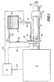
- Figure 1 illustrates a pollution control system as might be used to reduce NOx emissions from the exhaust of a diesel engine 3.
- the system includes an engine exhaust conduit 4 in fluid communication with a catalytic reactor 5, a reagent reservoir 6 holding reagent 7, a central processing unit 8 and an injector 10.
- Injector 10 is mounted on exhaust conduit 4 and fed reagent, for example, a solution of aqueous urea via supply line 9 extending from reservoir 7 to the injector.
- a pump 11 is used to pump the reagent to the injector at a predetermined pressure.
- Reagent 7 is circulated back to the reservoir via return line 12, the circulation of the reagent being shown by the arrows 7a.
- signals 13, representing engine operational parameters such as exhaust gas temperature, engine speed and fuel flow rate are monitored by central processing unit 8.
- central processing unit 8 sends control signals 14 and 15 to injector 10 and pump 11 respectively, the control signals commanding pump 11 to circulate reagent and injector 10 to inject or cease injecting reagent into exhaust gases 16 within the exhaust conduit 4.
- the reagent is atomized upon injection into the conduit and forms a mixture with the exhaust gases.
- This mixture enters the catalytic reactor 5 which contains a catalyst, such as activated carbon, or metals, such as platinum, tungsten or vanadium, which reduces NOx in the exhaust gases in the presence of the reagent.
- the exhaust exits the conduit 4 and passes to the atmosphere.
- reagent 7 is circulated continuously between the reservoir 6 and the injector 10 to cool the injector and minimize the dwell time of the reagent in the injector so that the reagent remains cool.
- Continuous reagent circulation is necessary for temperature-sensitive reagents, such as aqueous urea, which tend to solidify upon exposure to elevated temperatures of 300°C to 650°C as would be experienced in an engine exhaust system. It has been found to be important to keep the urea mixture below 140°C and preferably in a lower operating range between 5°C and 95°C to provide a margin of safety ensuring that solidification of the urea is prevented.
- FIG. 2 shows a cross-sectional view of the preferred embodiment of the injector 10 according to the invention.
- the injector is shown mounted on an exhaust gas conduit 4, only partially depicted, in cross-section.
- Injector 10 comprises a valve body 18 having an elongated cylindrical chamber 20 disposed therein. Chamber 20 is in fluid communication with an orifice 22 which opens onto the exhaust gases within conduit 4.
- a valve seat 24 Surrounding orifice 22 is a valve seat 24 which can have any practical shape but is preferably conical.
- a valve member in the form of an elongated valve plunger 26 is slidably mounted within chamber 20. Valve plunger 26 has an end 28 formed to sealingly interengage valve seat 24, as seen in Figure 2, thereby closing orifice 22 from fluid communication with chamber 20.
- Valve plunger 26 is movable within the chamber between the closed position shown in Figure 2 and an open position wherein end 28 is removed from sealing interengagment with valve seat 24. In the open position, orifice 22 is opened to fluid communication with chamber 20.
- the chamber 20 and the valve plunger 26 provide a means for circulating fluid, such as the reagent, through the valve for cooling the valve and for minimizing the dwell time of the reagent within the valve.
- the circulating means comprises an annular fluid passageway 30 formed between the relatively larger inner diameter of chamber 20 and the relatively smaller outer diameter of a section 32 of the valve-plunger 26.
- plunger section 32 is arranged adjacent to plunger end 28 and close to valve seat 24 and orifice 22.
- Positioning fluid passageway 30 close to the orifice allows the circulating fluid to directly cool an otherwise hot part of the valve body most sensitive to the adverse effects of heat.
- aqueous urea when used with this cooled valve, will not solidify anywhere within chamber 20.
- the urea could prevent plunger 26 from seating properly or could cause the plunger to seize in either the open or closed position and/or the orifice 22 could become clogged.
- plunger 26 further comprises a guide section 33 disposed adjacent to section 32 of the valve plunger.
- Guide section 33 preferably has a polygonal cross-section formed by a plurality of flats 33a intersecting at a plurality of corners 33 b.
- Flats 33a provide fluid circulation spaces adjacent to the chamber 20 and augment the cooling function of the fluid passageway 30.
- the flats also provide space for any debris formed within or brought into chamber 20 to wash out of the chamber with the circulating fluid.
- the corners 33b of the guide section 33 provide a stabilizing and a guiding function for plunger 26.
- the corners are toleranced to ride close to or in light contact with the wall of chamber 20 to provide support points which guide the plunger within the chamber to ensure proper seating of plunger end 28.
- a reduced circular cross-section 35 of plunger 26 Immediately above guide section 33 is a reduced circular cross-section 35 of plunger 26. Reduced section 35 provides an annular space for fluid to flow into the chamber through an inlet, described in detail below. Above the reduced section is a circular guide section 37. Circular guide section 37 provides the main guiding function for sliding motion of the plunger 26 within the chamber 20. The tolerance between the circular guide section and the chamber is sufficient to allow relative motion and lubrication of the plunger while still guiding the plunger's motion and forming a partial hydraulic seal between the plunger and the chamber.
- valve plunger and valve body Generally the specific tolerances required at the various sections between the valve plunger and the chamber will vary according to the operating temperature, operating pressure, the desired flow rate and circulation rate of the reagent, the tribological properties of the reagent and the materials chosen for the valve plunger and valve body. The tolerances for optimum injector performance are best obtained experimentally by a few field trials.
- Fluid inlet 34 is arranged within valve body 18 in fluid communication with chamber 20 and is externally connected to supply line 9 ( Figure 1). It is preferred that the fluid inlet be positioned to deliver fluid to chamber 20 in a region removed from the valve seat 24 adjacent to reduced section 25 and guide section 33, as shown in Figure 2. Positioning the fluid inlet upstream from the seat, as shown, allows the fluid to contact valve plunger 26 over a substantial length before it encounters the valve seat, thereby enhancing the cooling function of the fluid. Fluid, such as reagent 7, is pumped via pump 11 at a predetermined pressure into the fluid inlet 34 from which it flows along valve plunger 26 into annular fluid passageway 30.
- a fluid outlet 36 is provided to remove the fluid from the annular fluid passageway.
- Fluid outlet 36 is arranged within valve body 18 in fluid communication with chamber 20.
- fluid outlet 36 is positioned as shown in Figure 2 for removing fluid from chamber 20 in the region of the valve seat 24.
- Fluid outlet 36 is externally connected to return line 12 ( Figure 1), thus permitting the fluid (such as reagent 7) to circulate from reservoir 6, through supply line 9, through fluid inlet 34, into annular fluid passageway 30, through fluid outlet 36, through return line 12 and back into reservoir 6. This circulation keeps critical regions of the valve body 18 cool and minimizes the dwell time of the fluid in the injector.
- valve plunger 26 When the valve plunger 26 is moved from the closed position, shown in Figure 2, to an open position, plunger end 28 is removed from sealing interengagement with seat 24. This action opens orifice 22 and allows at least a portion of the circulating fluid to be expelled through the orifice and into exhaust conduit 4.
- actuating means are provided, preferably in the form of solenoid 38 mounted atop valve body 18. Solenoid 38 has an armature 40 connected to valve plunger 26. When the solenoid is energized, the armature 40 is drawn upward, thereby sliding valve plunger 26 within chamber 20 from the closed position to the open position.
- the solenoid would be energized, for example, in response to a signal 14 (see Figure 1) from central processing unit 8, which decides, based upon sensor input signals 13 and its preprogrammed algorithms, when reagent is needed for effective selective catalytic reduction of NOx emissions in the exhaust stream.
- valve plunger 26 is biased in the closed position by a biasing member, preferably in the form of a coil spring 42 coaxially disposed about valve plunger 26.
- the valve plunger has a shoulder 44 which serves as a lower spring seat against which the spring can push to bias the valve plunger.
- An upper plate 46 is fixed to the valve body 18 and serves as the upper spring seat, as well as a stop to limit the upward travel of the valve plunger.
- Spring 42 is located within a spring chamber 48 which is isolated from chamber 20 by seal 50.
- Seal 50 is preferably made of carbon reinforced Teflon® or glass reinforced Teflon® and prevents any corrosive reagent from entering the spring chamber and possibly attacking or fouling the spring and the solenoid.
- Injector 10 is shown mounted on exhaust conduit 4 by means of sleeve 52 which is welded to an opening in the conduit by weldment 54.
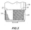
- valve body 18 has external threads 19 which engage matching internal threads 53 in sleeve 52 to attach the injector to the sleeve.
- the external threads 19 are not continuous around the circumference of valve body 18 but interrupted or discontinuous, as seen in Figure 3.
- the thread contact area is minimized by using intermittent arcs of threads subtending angles on the order of 20° arranged circumferentially around valve body 18, with flat regions 21 arranged between each thread arc.
- the flats have an across-the-flat dimension which is less than the root diameter of the thread on valve body 18 and, therefore, make no contact with sleeve 52.
- Heat shield 56 includes an outer metal plate 58 and a layer of insulating material in the form of a thermal gasket 60 interposed between outer plate 58 and valve body 18.
- outer plate 58 is made of stainless steel to resist the corrosive environment within the exhaust conduit.
- Gasket 60 is preferably made of a flexible graphite foil material whose low thermal conductivity serves to isolate valve body 18 from outer plate 58, reducing conductive heat transfer to the injector and thereby helping to keep the fluid circulating within the valve cool.
- Heat shield 56 surrounds the orifice 22 and has an aperture 62 which passes through both the outer plate and the insulating thermal gasket and permits fluid expelled from the injector to pass through the heat shield and into the conduit.
- the heat shield has a substantially planar surface which is preferably oriented perpendicular to the jet of fluid expelled from the injector.
- a radiant heat reflector 70 seen edge on in Figure 2.
- Reflector 70 is preferably a round disc of polished aluminum having an outer diameter of sufficient extent such that the surface 70a of the disc blocks radiant heat transfer from exhaust conduit 4 to parts of the injector which have a direct line of sight to the conduit.
- the reflector has a centrally positioned aperture 72 which fits around valve body 18 and sits atop sleeve 52 to mount the reflector between the exposed parts of the injector and the conduit 4. Reflector 70 is retained in position by a nut 74 which threads onto valve body 18.
- injection pressure relatively low to prevent the fluid jet or plume from the injector from over-penetrating into the exhaust gas stream and impinging on the sidewall of the conduit. Injection pressures within a range of 30 to 100 psi (0.21 to 0.69 MPa) have been found to prevent over-penetration. An injection pressure of 67 psi (0.46 MPa) is preferred for the injector according to the invention.
- an atomization hook 64 is provided. It is an advantage of the invention that no secondary atomization fluid is required.
- Hook 64 is mounted on the valve, preferably on the metal plate 58 of heat shield 56 as seen in Figure 2.
- the hook is made of stainless steel to withstand the corrosive environment within the exhaust conduit. Mounting the hook on the heat shield serves to thermally isolate the hook from the valve body 18. Because the hook extends into the exhaust stream, it will be hot, and being metal, it will tend to conduct heat readily. However, by mounting the hook on the heat shield heat conducted by the hook will be blocked by the thermal gasket 60, and heat transfer from the hook to the valve body will be minimized by this preferred mounting of the hook 64.
- Hook 64 has an end surface 66 which is positioned in a spaced-apart relation facing orifice 22.
- the valve plunger 26 When the valve plunger 26 is actuated into its open position by solenoid 38, expelling fluid at a predetermined pressure from orifice 22, the fluid jet will impinge on end surface 66. This impingement will cause further atomization of the fluid.
- the dispersion characteristics of the fluid are a function of the shape of the end surface, which is tuned to a particular size and shape of the exhaust stream to ensure maximum dispersion and penetration of the fluid without over-penetration.
- An injector wherein critical valve components are directly cooled by circulating fluid provides a component for a pollution control system which allows a corrosive and heat-sensitive reagent, such as aqueous urea, to be effectively employed to reduce NOx emissions and thereby ultimately attain greater fuel efficiency without the adverse effects of increased undesired emissions.
Landscapes
- Engineering & Computer Science (AREA)
- Chemical & Material Sciences (AREA)
- Health & Medical Sciences (AREA)
- Chemical Kinetics & Catalysis (AREA)
- Environmental & Geological Engineering (AREA)
- General Chemical & Material Sciences (AREA)
- Biomedical Technology (AREA)
- Analytical Chemistry (AREA)
- Oil, Petroleum & Natural Gas (AREA)
- General Engineering & Computer Science (AREA)
- Toxicology (AREA)
- Mechanical Engineering (AREA)
- Combustion & Propulsion (AREA)
- Life Sciences & Earth Sciences (AREA)
- Bioinformatics & Cheminformatics (AREA)
- Pharmacology & Pharmacy (AREA)
- Diabetes (AREA)
- Animal Behavior & Ethology (AREA)
- General Health & Medical Sciences (AREA)
- Public Health (AREA)
- Veterinary Medicine (AREA)
- Nuclear Medicine, Radiotherapy & Molecular Imaging (AREA)
- Medicinal Chemistry (AREA)
- Endocrinology (AREA)
- Organic Chemistry (AREA)
- Exhaust Gas After Treatment (AREA)
- Nozzles (AREA)
- Magnetically Actuated Valves (AREA)
- Fuel-Injection Apparatus (AREA)
- Exhaust Silencers (AREA)
- Physical Or Chemical Processes And Apparatus (AREA)
- Treating Waste Gases (AREA)
- Exhaust Gas Treatment By Means Of Catalyst (AREA)
- Jet Pumps And Other Pumps (AREA)
Claims (12)
- Vorrichtung zum Einspritzen eines Strahls eines flüssigen Reagenzes (7) in zerstäubter Form in eine Abgasanlage mit einer Abgasleitung (4), die heiße Gase (16) enthält, und einem einen Katalysator enthaltenden Reaktor (5), wobei der Reaktor (5) in Strömungsverbindung mit der Abgasleitung (4) ist und wobei die Vorrichtung aufweist::gekennzeichnet durch eine Rückleitung (12), die sich zwischen dem Reservoir (6) und dem Ventil (18,26) erstreckt, um das flüssige Reagenz (7) von dem Ventil (18,26) zu dem Reservoir (6) zurückzuführen;ein Reservoir (6), das das flüssige Reagenz (7) enthält;ein Ventil (18,26), das an der Leitung (4) befestigt ist und eine Öffnung (22) hat, die eine Strömungsverbindung zwischen dem Ventil (18,26) und der Leitung (4) liefert;eine Hinleitung (9), die sich zwischen dem Reservoir (6) und dem Ventil (18,26) erstreckt, um das flüssige Reagenz (7) zu dem Ventil (18,26) zur Einspritzung zu führen;einen Einlass (34), der in dem Ventil (18,26) angeordnet und in Strömungsverbindung mit der Hinleitung (9) ist;
Mittel (11 ) zum Zirkulieren (7a) des flüssigen Reagenzes (7) von dem Reservoir (6) durch das Ventil (18,26) mit einem vorbestimmten Druck;
den Einlass (34), der das Reagenz (7) zu einem der Öffnung (22) benachbarten Bereich des Ventils führt;
einen Auslass (36), der in dem Ventil (18,26) angeordnet und in Strömungsverbindung mit der Rückleitung (12) ist, wobei der Auslass (36) für die Entfernung des Reagenzes (7) aus dem zu der Öffnung (22) benachbarten Bereich des Ventils (18,26) sorgt; und
Mittel (38) zum Betätigen des Ventils (18,26) zwischen einer offenen Stellung, in der die Öffnung (22) geöffnet ist und wenigstens ein Teil des durch das Ventil (18,26) zirkulierenden flüssigen Reagenzes (7) durch die Öffnung (22) in die Leitung (4) mit dem vorbestimmten Druck ausgetrieben wird, und einer geschlossenen Stellung, in der die Öffnung (22) mittels des Ventils (18,26) geschlossen ist, wobei die Zirkulationsmittel (11) für die Zirkulation der Flüssigkeit (7) unabhängig von der Stellung des Ventils (18,26) sorgen. - Vorrichtung nach Anspruch 1, bei der das Ventil (18,26) aus nichtrostendern Stahl hergestellt ist.
- Vorrichtung nach Anspruch 1, bei der der vorbestimmte Druck zwischen 30 psi (0,21 MPa) und 100 psi (0,69 MPa) liegt.
- Vorrichtung nach Anspruch 1, bei der der vorbestimmte Druck zwischen 60 psi (0,42 MPa) und 75 psi (0,52 MPa) liegt.
- Vorrichtung nach Anspruch 1, bei der der vorbestimmte Druck ungefähr 67 psi (0,46 MPa) beträgt.
- Vorrichtung nach Anspruch 1, welche ferner einen an dem Ventil (18,26) befestigten und die Öffnung (22) umgebenden Hitzeschild (56) aufweist, wobei der Hitzeschild (56) eine im Wesentlichen ebene Fläche aufweist, die senkrecht zu dem Strahl des flüssigen Reagenzes (7) orientiert ist.
- Vorrichtung nach Anspruch 1, welche ferner einen Strahlungswärmereflektor (70) mit einer zwischen der Abgasleitung (4) und dem Injektor (10) positionierten Fläche (70a) zum Blockieren von Strahlungswärme von der Abgasleitung (4) aufweist
- Verfahren zum Reduzieren von Emissionen von Oxiden von Stickstoff aus einem Verbrennungsprozess, wobei ein temperaturempfindliches flüssiges Reagenz (7) in einen Strom von Abgasen (16) aus dem Verbrennungsprozess eingespritzt wird und die Abgase (16) und das Reagenz (7) durch einen katalytischen Reaktor (5), der die Oxide von Stickstoff in der Anwesenheit des Reagenzes (7) reduziert, geführt werden, wobei das Verfahren die Schritte aufweist:gekennzeichnet durch Kühlen des Injektors (10), indem das Reagenz (7) kontinuierlich durch diesen hindurch und zwischen einem das flüssige Reagenz (7) enthaltenden Reservoir (6) zirkuliert wird, wodurch sowohl der Injektor (10) als auch das Reagenz (7) in dem Injektor (10) unterhalb einer Temperatur, bei der das Reagenz (7) festwird, gehalten werden; undZur-Verfügung-Stellen eines Injektors (10) mit einer Öffnung (22) zum Zerstäuben des flüssigen Reagenzes (7);Positionieren eines Abschnitts des Injektors (10) mit der Öffnung (22) innerhalb des Stroms von Abgasen (16);
Einspritzen eines Teils des Reagenzes (7) in den Abgasstrom (16) stromaufwärts von dem Reaktor (5). - Verfahren nach Anspruch 8, wobei das Reagenz (7) eine wässrige Harnstofflösung ist.
- Verfahren nach Anspruch 9, wobei der Harnstoff eine Konzentration zwischen 25 % und 35 % besitzt.
- Verfahren nach Anspruch 8, wobei der Verbrennungsprozess in einer Verbrennungskraftmaschine (3) stattfindet.
- Verfahren nach Anspruch 11, wobei die Maschine (3) eine Dieselmaschine ist.
Applications Claiming Priority (3)
| Application Number | Priority Date | Filing Date | Title |
|---|---|---|---|
| US164304 | 1998-10-01 | ||
| US09/164,304 US6279603B1 (en) | 1998-10-01 | 1998-10-01 | Fluid-cooled injector |
| PCT/US1999/022386 WO2000018491A1 (en) | 1998-10-01 | 1999-09-27 | Fluid-cooled injector |
Publications (3)
| Publication Number | Publication Date |
|---|---|
| EP1117469A1 EP1117469A1 (de) | 2001-07-25 |
| EP1117469A4 EP1117469A4 (de) | 2002-06-05 |
| EP1117469B1 true EP1117469B1 (de) | 2003-12-10 |
Family
ID=22593890
Family Applications (1)
| Application Number | Title | Priority Date | Filing Date |
|---|---|---|---|
| EP19990960107 Expired - Lifetime EP1117469B1 (de) | 1998-10-01 | 1999-09-27 | Flüssig-gekühlter einspritzer |
Country Status (10)
| Country | Link |
|---|---|
| US (2) | US6279603B1 (de) |
| EP (1) | EP1117469B1 (de) |
| JP (2) | JP3851775B2 (de) |
| CN (2) | CN1483924A (de) |
| AT (1) | ATE255950T1 (de) |
| AU (1) | AU1704500A (de) |
| CA (1) | CA2345807C (de) |
| DE (1) | DE69913549T2 (de) |
| ES (1) | ES2209531T3 (de) |
| WO (1) | WO2000018491A1 (de) |
Cited By (2)
| Publication number | Priority date | Publication date | Assignee | Title |
|---|---|---|---|---|
| WO2018219947A1 (en) | 2017-05-29 | 2018-12-06 | Liebherr-Components Colmar Sas | Reductant injection system |
| EP3741968A2 (de) | 2019-04-26 | 2020-11-25 | Liebherr-Components Colmar SAS | Reduktionsmitteldosiersystem für einen scr-katalysator |
Families Citing this family (127)
| Publication number | Priority date | Publication date | Assignee | Title |
|---|---|---|---|---|
| US7389792B2 (en) * | 1998-12-24 | 2008-06-24 | Nl Technologies, Ltd. | Dip tube valve assembly |
| JP3525787B2 (ja) | 1999-02-24 | 2004-05-10 | トヨタ自動車株式会社 | 内燃機関の排気浄化装置 |
| DE19919426C1 (de) * | 1999-04-28 | 2000-03-30 | Siemens Ag | Ventilaufnahmevorrichtung für ein Dosierventil einer Abgasnachbehandlungsanlage |
| DE10107618A1 (de) * | 2001-02-17 | 2002-08-29 | Pierburg Ag | Ventilanordnung zur Druckregelung der Kraftstoffzufuhr bei einer Brennkraftmaschine |
| US6669057B2 (en) * | 2001-10-31 | 2003-12-30 | Nordson Corporation | High-speed liquid dispensing modules |
| CA2466181A1 (en) * | 2001-11-09 | 2003-05-15 | Clean Diesel Technologies, Inc. | Continuously-variable control of pollution reducing chemicals for combustion sources |
| US6814303B2 (en) * | 2002-04-03 | 2004-11-09 | Cleaire Advanced Emission Controls | Fluid-cooled mount for an injector |
| US6996976B2 (en) * | 2002-04-03 | 2006-02-14 | Cleaire Advanced Emmision Controls | Apparatus and method for mounting a device to a pipe |
| AU2003273138A1 (en) * | 2002-05-07 | 2003-12-12 | Extengine Transport Systems | Emission control system |
| US7497076B2 (en) * | 2002-05-07 | 2009-03-03 | Extengine Transport Systems | Emission control system |
| US6887284B2 (en) * | 2002-07-12 | 2005-05-03 | Dannie B. Hudson | Dual homogenization system and process for fuel oil |
| US6941746B2 (en) * | 2002-11-21 | 2005-09-13 | Combustion Components Associates, Inc. | Mobile diesel selective catalytic reduction systems and methods |
| EP1644619A2 (de) * | 2003-06-12 | 2006-04-12 | Donaldson Company, Inc. | Verfahren zur abgabe von kraftstoff in den instationären fluss eines abgassystems |
| DE10332114A1 (de) * | 2003-07-09 | 2005-01-27 | Robert Bosch Gmbh | Gekühlte Vorrichtung zur Dosierung von Reduktionsmittel zum Abgas eines Verbrennungsmotors |
| WO2005028826A1 (ja) * | 2003-09-19 | 2005-03-31 | Nissan Diesel Motor Co., Ltd. | エンジンの排気浄化装置 |
| JP2005127318A (ja) * | 2003-09-19 | 2005-05-19 | Nissan Diesel Motor Co Ltd | エンジンの排気浄化装置 |
| DE602004015317D1 (de) * | 2003-09-30 | 2008-09-04 | Nissan Diesel Motor Co | Abgasentgiftungsvorrichtung für motor |
| US7186396B2 (en) * | 2003-11-26 | 2007-03-06 | Asemblon, Inc. | Method for hydrogen storage and delivery |
| EP2383444B1 (de) * | 2004-02-02 | 2012-12-19 | Nissan Diesel Motor Co., Ltd. | Abgasreinigungsvorrichtung für einen Motor |
| EP1712754A4 (de) | 2004-02-02 | 2010-09-29 | Nissan Diesel Motor Co | Vorrichtung zur abgasreinigung eines verbrennungsmotors |
| DE102004015805B4 (de) * | 2004-03-29 | 2007-07-26 | J. Eberspächer GmbH & Co. KG | Vorrichtung zum Einbringen einer Flüssigkeit in einen Abgasstrang |
| US8047452B2 (en) * | 2004-04-26 | 2011-11-01 | Tenneco Automotive Operating Company Inc. | Method and apparatus for injecting atomized fluids |
| US7467749B2 (en) * | 2004-04-26 | 2008-12-23 | Tenneco Automotive Operating Company Inc. | Methods and apparatus for injecting atomized reagent |
| DE102004025062B4 (de) * | 2004-05-18 | 2006-09-14 | Hydraulik-Ring Gmbh | Gefriertaugliches Dosierventil |
| DE102004048336A1 (de) * | 2004-10-01 | 2006-04-13 | J. Eberspächer GmbH & Co. KG | Abgasanlage für eine Brennkraftmaschine |
| JP3714559B1 (ja) * | 2004-11-05 | 2005-11-09 | 日産ディーゼル工業株式会社 | 排気浄化装置 |
| DE102004056791B4 (de) * | 2004-11-24 | 2007-04-19 | J. Eberspächer GmbH & Co. KG | Abgasanlage |
| DE102004058542A1 (de) * | 2004-12-03 | 2006-06-08 | Nordson Corporation, Westlake | Rotationsauftragskopf und Etikettieranlage zum Aufbringen von Etiketten |
| EP1698768A1 (de) * | 2005-03-02 | 2006-09-06 | Hydraulik-Ring Gmbh | Einspritzvorrichtung zur Abgasnachbehandlung |
| US7771556B2 (en) | 2005-07-01 | 2010-08-10 | Nordson Corporation | Apparatus and process to apply adhesive during labeling operations |
| JP2007032472A (ja) * | 2005-07-28 | 2007-02-08 | Hitachi Ltd | 尿素水を用いた排気処理装置 |
| DE102005061145A1 (de) * | 2005-12-21 | 2007-06-28 | Robert Bosch Gmbh | Abgasnachbehandlungsvorrichtung |
| US20070210926A1 (en) * | 2006-03-08 | 2007-09-13 | Chavez Jon P | Apparatus and Method for Communicating Cues During a Musical Performance |
| CN100446838C (zh) * | 2006-03-29 | 2008-12-31 | 宝山钢铁股份有限公司 | 洗涤塔雾化喷射装置 |
| US20070228191A1 (en) * | 2006-03-31 | 2007-10-04 | Caterpillar Inc. | Cooled nozzle assembly for urea/water injection |
| US7735756B2 (en) * | 2006-04-12 | 2010-06-15 | Combustion Components Associates, Inc. | Advanced mechanical atomization for oil burners |
| DE102006020439A1 (de) * | 2006-05-03 | 2007-11-08 | Purem Abgassysteme Gmbh & Co. Kg | Verfahren und Vorrichtung zum Dosieren eines Reduktionsmittels in ein Abgassystem einer Brennkraftmaschine |
| JP4662886B2 (ja) * | 2006-05-26 | 2011-03-30 | ボッシュ株式会社 | 内燃機関の排気浄化装置 |
| US20070277505A1 (en) * | 2006-05-30 | 2007-12-06 | Ford Global Technologies, Llc | Venting of on-board vehicle emissions treatment system |
| CA2655129C (en) * | 2006-05-31 | 2012-12-11 | Tenneco Automotive Operating Company, Inc. | Method and apparatus for reducing emissions in diesel engines |
| US20070289288A1 (en) * | 2006-06-19 | 2007-12-20 | Ford Global Technologies, Llc | Venting of on-board vehicle emissions treatment system with pressure assist |
| JP4799289B2 (ja) * | 2006-06-26 | 2011-10-26 | Udトラックス株式会社 | エンジンの排気浄化装置 |
| JP4804242B2 (ja) * | 2006-06-26 | 2011-11-02 | Udトラックス株式会社 | エンジンの排気浄化装置 |
| EP1878920B1 (de) * | 2006-07-12 | 2011-06-08 | Delphi Technologies Holding S.à.r.l. | Dosierpumpe für eines Reduktionsmittels |
| US7497077B2 (en) * | 2006-07-26 | 2009-03-03 | Southwest Research Institute | System and method for dispensing an aqueous urea solution into an exhaust gas stream |
| JP4888171B2 (ja) * | 2006-07-27 | 2012-02-29 | 株式会社デンソー | 排気浄化装置 |
| US8109077B2 (en) * | 2006-10-11 | 2012-02-07 | Tenneco Automotive Operating Company Inc. | Dual injector system for diesel emissions control |
| JP4656039B2 (ja) * | 2006-10-19 | 2011-03-23 | 株式会社デンソー | エンジンの排気浄化装置 |
| US9151201B2 (en) * | 2006-11-08 | 2015-10-06 | Continental Automotive Systems, Inc. | Laser welded automotive diesel exhaust HC dosing valve |
| DE102006053485A1 (de) * | 2006-11-14 | 2008-05-15 | Robert Bosch Gmbh | Verfahren zum Betreiben eines Reagenzmittel-Dosierventils und Vorrichtung zur Durchführung des Verfahrens |
| DE102006062491A1 (de) * | 2006-12-28 | 2008-07-03 | Robert Bosch Gmbh | Vorrichtung zur Dosierung von Kraftstoff zum Abgassystem eines Verbrennungsmotors |
| US8171721B2 (en) | 2007-01-22 | 2012-05-08 | International Engine Intellectual Property Company, Llc | Closed loop control of exhaust system fluid dosing |
| DE102007004687B4 (de) | 2007-01-25 | 2012-03-01 | Hydraulik-Ring Gmbh | Volumensmengenabgabeeinheit und Verfahren zur Kalibrierung der Druckausgangssignal-Volumensmenge-Charakteristik |
| US8453436B2 (en) * | 2007-03-08 | 2013-06-04 | Mack Trucks, Inc. | Aftertreatment injector anti-fouling device |
| US7818960B2 (en) | 2007-03-14 | 2010-10-26 | Gm Global Technology Operations, Inc. | SCR cold start heating system for a diesel exhaust |
| EP2538049B1 (de) * | 2007-03-30 | 2015-03-18 | Continental Automotive Systems US, Inc. | Reduktionsmittelabgabeeinheit für selektive katalytische Reduktion |
| US7797932B2 (en) * | 2007-04-30 | 2010-09-21 | Cummins, Inc | Apparatus and system for enhancing aftertreatment regeneration |
| JP4174685B1 (ja) * | 2007-05-31 | 2008-11-05 | 三菱自動車工業株式会社 | 内燃機関の排気浄化装置 |
| US8056326B2 (en) | 2007-05-31 | 2011-11-15 | Caterpillar Inc. | Regeneration device having cooled injection housing |
| ATE488677T1 (de) * | 2007-07-09 | 2010-12-15 | Delphi Technologies Holding | Dosierungssystem für reagensmittel |
| JP5001793B2 (ja) * | 2007-11-13 | 2012-08-15 | 三菱ふそうトラック・バス株式会社 | 排気浄化装置 |
| US20090137350A1 (en) * | 2007-11-26 | 2009-05-28 | Jason Lenig | Game Ball with Enhanced in Flight Movement |
| DE102008012780B4 (de) * | 2008-03-05 | 2012-10-04 | Hydraulik-Ring Gmbh | Abgasnachbehandlungseinrichtung |
| US8127538B2 (en) * | 2008-03-21 | 2012-03-06 | Ford Global Technologies, Llc | Liquid injector assembly with a flanged connector connection |
| EP2105592B1 (de) * | 2008-03-28 | 2010-03-24 | Magneti Marelli S.p.A. | Haltevorrichtung für einen Injektor in einem Abgassystem einer Brennkraftmaschine |
| US8499550B2 (en) * | 2008-05-20 | 2013-08-06 | Cummins Ip, Inc. | Apparatus, system, and method for controlling particulate accumulation on an engine filter during engine idling |
| DE102008049097A1 (de) * | 2008-09-26 | 2010-04-01 | Daimler Ag | Kraftwagen mit System zum Zuführen von Flüssigkeit in ein anderes Medium, insbesondere zum Zuführen eines Reduktionsmittels in das Abgas eines Verbrennungsmotors |
| US7980483B2 (en) * | 2008-10-13 | 2011-07-19 | Eaton Corporation | Injector for a fluid injection system |
| US8459012B2 (en) * | 2008-11-19 | 2013-06-11 | Caterpillar Inc. | Method for purging a dosing system |
| US7966979B2 (en) * | 2009-01-26 | 2011-06-28 | Caterpillar Inc. | Mounting and cooling device for emissions system electronics |
| JP5727941B2 (ja) * | 2009-02-02 | 2015-06-03 | テネコ オートモティブ オペレーティング カンパニー インコーポレイテッドTenneco Automotive Operating Company Inc. | 噴射器取り付け装置 |
| US8517284B2 (en) * | 2009-05-13 | 2013-08-27 | Caterpillar Inc. | System and method for internal cooling of a fuel injector |
| DE102009028030A1 (de) * | 2009-07-27 | 2011-02-03 | Robert Bosch Gmbh | Montageeinheit zur Befestigung eines Einspritzorgans an einem Abgasstrang und Abgasnachbehandlungsanordnung |
| DE102009035940C5 (de) * | 2009-08-03 | 2017-04-20 | Cummins Ltd. | SCR-Abgasnachbehandlungseinrichtung |
| FR2949532B1 (fr) * | 2009-09-03 | 2011-09-23 | Air Liquide | Calorifugation des canalisations d'une installation de travail par jets de fluide cryogenique |
| US8429903B2 (en) * | 2009-12-22 | 2013-04-30 | Caterpillar Inc. | Radial mounting for regeneration device |
| US8789361B2 (en) * | 2010-01-26 | 2014-07-29 | Deere & Company | Diesel aftertreatment regeneration system and method |
| US8740113B2 (en) | 2010-02-10 | 2014-06-03 | Tenneco Automotive Operating Company, Inc. | Pressure swirl flow injector with reduced flow variability and return flow |
| US8973895B2 (en) | 2010-02-10 | 2015-03-10 | Tenneco Automotive Operating Company Inc. | Electromagnetically controlled injector having flux bridge and flux break |
| JP5748781B2 (ja) * | 2010-02-10 | 2015-07-15 | テネコ オートモティブ オペレーティング カンパニー インコーポレイテッドTenneco Automotive Operating Company Inc. | インジェクターを通して試薬を方向付ける方法 |
| US9683472B2 (en) | 2010-02-10 | 2017-06-20 | Tenneco Automotive Operating Company Inc. | Electromagnetically controlled injector having flux bridge and flux break |
| SE534974C2 (sv) * | 2010-06-21 | 2012-03-06 | Scania Cv Ab | Förfarande och anordning för att baserat på en doseringsenhets kylbehov bestämma miniminivån i en reduktionsmedelsbehållare i ett SCR-system |
| SE536873C2 (sv) * | 2010-06-21 | 2014-10-14 | Scania Cv Ab | HC-doseringssystem för avgasrening samt förfarande för kylning därav |
| US8438839B2 (en) | 2010-10-19 | 2013-05-14 | Tenneco Automotive Operating Company Inc. | Exhaust gas stream vortex breaker |
| CN101988412A (zh) * | 2010-11-12 | 2011-03-23 | 无锡市凯龙汽车设备制造有限公司 | 柴油机scr喷射头 |
| US8549840B2 (en) | 2010-11-12 | 2013-10-08 | Cummins Cal Pacific, Llc | Fluid injector |
| DE102010061222B4 (de) | 2010-12-14 | 2015-05-07 | Cummins Ltd. | SCR-Abgasnachbehandlungseinrichtung |
| WO2012138373A1 (en) * | 2011-04-04 | 2012-10-11 | Mack Trucks, Inc. | Fluid cooled injector and exhaust aftertreatment system, vehicle, and method using a fluid cooled injector |
| DE102011075381A1 (de) * | 2011-05-06 | 2012-11-08 | Robert Bosch Gmbh | Injektor zur Dosierung von Reduktionsmittel zum Abgas einer Brennkraftmaschine |
| US8910882B2 (en) | 2011-06-23 | 2014-12-16 | Caterpillar Inc. | Fuel injector having reduced armature cavity pressure |
| US9726063B2 (en) | 2011-09-08 | 2017-08-08 | Tenneco Automotive Operating Company Inc. | In-line flow diverter |
| US9347355B2 (en) | 2011-09-08 | 2016-05-24 | Tenneco Automotive Operating Company Inc. | In-line flow diverter |
| US8677738B2 (en) | 2011-09-08 | 2014-03-25 | Tenneco Automotive Operating Company Inc. | Pre-injection exhaust flow modifier |
| US20130126644A1 (en) * | 2011-11-22 | 2013-05-23 | Jeremy Popovich | Threaded Injector Mount |
| US8978364B2 (en) | 2012-05-07 | 2015-03-17 | Tenneco Automotive Operating Company Inc. | Reagent injector |
| US8910884B2 (en) | 2012-05-10 | 2014-12-16 | Tenneco Automotive Operating Company Inc. | Coaxial flow injector |
| US20140054394A1 (en) * | 2012-08-27 | 2014-02-27 | Continental Automotive Systems Us, Inc. | Reductant delivery unit for automotive selective catalytic reduction systems - active cooling |
| US9511350B2 (en) | 2013-05-10 | 2016-12-06 | Clean Diesel Technologies, Inc. (Cdti) | ZPGM Diesel Oxidation Catalysts and methods of making and using same |
| US9511355B2 (en) | 2013-11-26 | 2016-12-06 | Clean Diesel Technologies, Inc. (Cdti) | System and methods for using synergized PGM as a three-way catalyst |
| US20140274662A1 (en) | 2013-03-15 | 2014-09-18 | Cdti | Systems and Methods for Variations of ZPGM Oxidation Catalysts Compositions |
| US9771534B2 (en) | 2013-06-06 | 2017-09-26 | Clean Diesel Technologies, Inc. (Cdti) | Diesel exhaust treatment systems and methods |
| DE102013211684A1 (de) * | 2013-06-20 | 2014-12-24 | Robert Bosch Gmbh | Kühlkörper für Einspritzventil |
| US9545626B2 (en) | 2013-07-12 | 2017-01-17 | Clean Diesel Technologies, Inc. | Optimization of Zero-PGM washcoat and overcoat loadings on metallic substrate |
| JP6111948B2 (ja) * | 2013-09-19 | 2017-04-12 | トヨタ自動車株式会社 | 内燃機関の排気浄化装置 |
| JP6177641B2 (ja) * | 2013-09-26 | 2017-08-09 | 株式会社ニフコ | 蓋体取付部材 |
| JP5880514B2 (ja) * | 2013-10-02 | 2016-03-09 | 株式会社デンソー | エンジンの排気浄化システム |
| US9511358B2 (en) | 2013-11-26 | 2016-12-06 | Clean Diesel Technologies, Inc. | Spinel compositions and applications thereof |
| US9475004B2 (en) | 2014-06-06 | 2016-10-25 | Clean Diesel Technologies, Inc. | Rhodium-iron catalysts |
| DE102014215084C5 (de) * | 2014-07-31 | 2023-10-05 | Purem GmbH | Injektionseinrichtung und zugehöriges Herstellungsverfahren |
| US9731279B2 (en) | 2014-10-30 | 2017-08-15 | Clean Diesel Technologies, Inc. | Thermal stability of copper-manganese spinel as Zero PGM catalyst for TWC application |
| US9700841B2 (en) | 2015-03-13 | 2017-07-11 | Byd Company Limited | Synergized PGM close-coupled catalysts for TWC applications |
| US9951706B2 (en) | 2015-04-21 | 2018-04-24 | Clean Diesel Technologies, Inc. | Calibration strategies to improve spinel mixed metal oxides catalytic converters |
| CN106285854B (zh) * | 2015-05-07 | 2019-08-27 | 浙江福爱电子有限公司 | 一种scr液体喷射装置 |
| JP6345628B2 (ja) * | 2015-05-26 | 2018-06-20 | コベルコ建機株式会社 | 還元剤インジェクタ用ガスケット及びそれを備えた排気ガス後処理装置 |
| US10605213B2 (en) * | 2015-08-21 | 2020-03-31 | Cummins Inc. | Nozzle combustion shield and sealing member with improved heat transfer capabilities |
| US10533472B2 (en) | 2016-05-12 | 2020-01-14 | Cdti Advanced Materials, Inc. | Application of synergized-PGM with ultra-low PGM loadings as close-coupled three-way catalysts for internal combustion engines |
| DE102016209269A1 (de) * | 2016-05-30 | 2017-11-30 | Robert Bosch Gmbh | Kühlkörper für ein Einspritz-/Dosierventil |
| US9861964B1 (en) | 2016-12-13 | 2018-01-09 | Clean Diesel Technologies, Inc. | Enhanced catalytic activity at the stoichiometric condition of zero-PGM catalysts for TWC applications |
| WO2018190843A1 (en) | 2017-04-13 | 2018-10-18 | Cummins Emission Solutions Inc. | Dosing module for use in aftertreatment systems for internal combustion engines |
| US10265684B2 (en) | 2017-05-04 | 2019-04-23 | Cdti Advanced Materials, Inc. | Highly active and thermally stable coated gasoline particulate filters |
| US10753252B2 (en) * | 2017-06-14 | 2020-08-25 | Vitesco Technologies USA, LLC. | Thermally isolated reductant dosing unit with hermetic seal |
| US10738256B1 (en) | 2017-12-22 | 2020-08-11 | TerSol, LLC | Fuel additive systems, compositions, and methods |
| US10704444B2 (en) | 2018-08-21 | 2020-07-07 | Tenneco Automotive Operating Company Inc. | Injector fluid filter with upper and lower lip seal |
| JP2020176602A (ja) * | 2019-04-22 | 2020-10-29 | 株式会社デンソー | 流体噴射装置及び流体噴射システム |
| US11268417B2 (en) | 2019-06-26 | 2022-03-08 | Cummins Emission Solutions Inc. | Liquid only lance injector |
| US11225716B2 (en) | 2019-11-27 | 2022-01-18 | Tokyo Electron Limited | Internally cooled multi-hole injectors for delivery of process chemicals |
| CN115246662B (zh) * | 2021-04-27 | 2024-05-28 | 邢台旭阳煤化工有限公司 | 苯加氢废水的处理装置及处理方法 |
Family Cites Families (13)
| Publication number | Priority date | Publication date | Assignee | Title |
|---|---|---|---|---|
| US2540663A (en) * | 1946-11-25 | 1951-02-06 | Merit Engineering And Mfg Co | Spray device |
| US3680537A (en) * | 1969-04-17 | 1972-08-01 | Nippon Denso Co | Fuel supply device for internal combustion engines |
| DE2644135A1 (de) * | 1976-09-30 | 1978-04-06 | Daimler Benz Ag | Einspritzventil |
| KR950012137B1 (ko) * | 1989-02-02 | 1995-10-14 | 닛뽄 쇼크바이 카가꾸 고오교오 가부시기가이샤 | 디이젤엔진 배기가스 중의 질소산화물 제거방법 |
| US4964471A (en) * | 1989-09-01 | 1990-10-23 | Cominco Ltd. | Sprinkler system and sprinkler assembly therefor |
| DE3935402C1 (de) * | 1989-10-24 | 1991-02-21 | Martin Gmbh Fuer Umwelt- Und Energietechnik, 8000 Muenchen, De | |
| US5189876A (en) * | 1990-02-09 | 1993-03-02 | Toyota Jidosha Kabushiki Kaisha | Exhaust gas purification system for an internal combustion engine |
| JP2887933B2 (ja) * | 1991-03-13 | 1999-05-10 | トヨタ自動車株式会社 | 内燃機関の排気浄化装置 |
| US5184462A (en) * | 1991-03-19 | 1993-02-09 | Oskar Schatz | Method and an apparatus for the treatment of exhaust gas from an IC engine |
| US5620142A (en) * | 1992-07-23 | 1997-04-15 | Elkas; Michael V. | Jeweled orifice fog nozzle |
| US5522218A (en) * | 1994-08-23 | 1996-06-04 | Caterpillar Inc. | Combustion exhaust purification system and method |
| JPH0932540A (ja) * | 1995-07-13 | 1997-02-04 | Hino Motors Ltd | ディーゼルエンジンの排ガス浄化装置 |
| US5976475A (en) * | 1997-04-02 | 1999-11-02 | Clean Diesel Technologies, Inc. | Reducing NOx emissions from an engine by temperature-controlled urea injection for selective catalytic reduction |
-
1998
- 1998-10-01 US US09/164,304 patent/US6279603B1/en not_active Expired - Lifetime
-
1999
- 1999-09-27 JP JP2000572005A patent/JP3851775B2/ja not_active Expired - Fee Related
- 1999-09-27 WO PCT/US1999/022386 patent/WO2000018491A1/en not_active Ceased
- 1999-09-27 AT AT99960107T patent/ATE255950T1/de not_active IP Right Cessation
- 1999-09-27 AU AU17045/00A patent/AU1704500A/en not_active Abandoned
- 1999-09-27 CN CNA03106339XA patent/CN1483924A/zh active Pending
- 1999-09-27 CA CA 2345807 patent/CA2345807C/en not_active Expired - Fee Related
- 1999-09-27 CN CNB99813726XA patent/CN1137750C/zh not_active Expired - Fee Related
- 1999-09-27 ES ES99960107T patent/ES2209531T3/es not_active Expired - Lifetime
- 1999-09-27 DE DE1999613549 patent/DE69913549T2/de not_active Expired - Lifetime
- 1999-09-27 EP EP19990960107 patent/EP1117469B1/de not_active Expired - Lifetime
-
2001
- 2001-07-09 US US09/901,180 patent/US20020001554A1/en not_active Abandoned
-
2003
- 2003-03-12 JP JP2003065834A patent/JP3863120B2/ja not_active Expired - Fee Related
Cited By (2)
| Publication number | Priority date | Publication date | Assignee | Title |
|---|---|---|---|---|
| WO2018219947A1 (en) | 2017-05-29 | 2018-12-06 | Liebherr-Components Colmar Sas | Reductant injection system |
| EP3741968A2 (de) | 2019-04-26 | 2020-11-25 | Liebherr-Components Colmar SAS | Reduktionsmitteldosiersystem für einen scr-katalysator |
Also Published As
| Publication number | Publication date |
|---|---|
| US6279603B1 (en) | 2001-08-28 |
| EP1117469A4 (de) | 2002-06-05 |
| CN1483924A (zh) | 2004-03-24 |
| US20020001554A1 (en) | 2002-01-03 |
| DE69913549D1 (de) | 2004-01-22 |
| JP3863120B2 (ja) | 2006-12-27 |
| CN1137750C (zh) | 2004-02-11 |
| JP2003328735A (ja) | 2003-11-19 |
| WO2000018491A1 (en) | 2000-04-06 |
| CA2345807A1 (en) | 2000-04-06 |
| DE69913549T2 (de) | 2004-11-18 |
| AU1704500A (en) | 2000-04-17 |
| WO2000018491A9 (en) | 2000-10-19 |
| ATE255950T1 (de) | 2003-12-15 |
| CA2345807C (en) | 2007-01-09 |
| JP3851775B2 (ja) | 2006-11-29 |
| ES2209531T3 (es) | 2004-06-16 |
| CN1328479A (zh) | 2001-12-26 |
| JP2002525491A (ja) | 2002-08-13 |
| EP1117469A1 (de) | 2001-07-25 |
Similar Documents
| Publication | Publication Date | Title |
|---|---|---|
| EP1117469B1 (de) | Flüssig-gekühlter einspritzer | |
| CA2563764C (en) | Methods and apparatus for injecting atomized fluid | |
| KR101460967B1 (ko) | 디젤엔진의 배기가스를 감소시키는 방법과 장치 | |
| US8047452B2 (en) | Method and apparatus for injecting atomized fluids | |
| US8438839B2 (en) | Exhaust gas stream vortex breaker | |
| US8998114B2 (en) | Pressure swirl flow injector with reduced flow variability and return flow | |
| US20110266370A1 (en) | Pressure swirl flow injector with reduced flow variability and return flow |
Legal Events
| Date | Code | Title | Description |
|---|---|---|---|
| PUAI | Public reference made under article 153(3) epc to a published international application that has entered the european phase |
Free format text: ORIGINAL CODE: 0009012 |
|
| 17P | Request for examination filed |
Effective date: 20010410 |
|
| AK | Designated contracting states |
Kind code of ref document: A1 Designated state(s): AT BE CH CY DE DK ES FI FR GB GR IE IT LI LU MC NL PT SE |
|
| AX | Request for extension of the european patent |
Free format text: AL;LT;LV;MK;RO;SI |
|
| A4 | Supplementary search report drawn up and despatched |
Effective date: 20020422 |
|
| AK | Designated contracting states |
Kind code of ref document: A4 Designated state(s): AT BE CH CY DE DK ES FI FR GB GR IE IT LI LU MC NL PT SE |
|
| RIC1 | Information provided on ipc code assigned before grant |
Free format text: 7B 01D 53/90 A, 7B 01D 53/86 B, 7F 01N 3/20 B |
|
| 17Q | First examination report despatched |
Effective date: 20021104 |
|
| GRAH | Despatch of communication of intention to grant a patent |
Free format text: ORIGINAL CODE: EPIDOS IGRA |
|
| GRAS | Grant fee paid |
Free format text: ORIGINAL CODE: EPIDOSNIGR3 |
|
| GRAA | (expected) grant |
Free format text: ORIGINAL CODE: 0009210 |
|
| AK | Designated contracting states |
Kind code of ref document: B1 Designated state(s): AT BE CH CY DE DK ES FI FR GB GR IE IT LI LU MC NL PT SE |
|
| PG25 | Lapsed in a contracting state [announced via postgrant information from national office to epo] |
Ref country code: NL Free format text: LAPSE BECAUSE OF FAILURE TO SUBMIT A TRANSLATION OF THE DESCRIPTION OR TO PAY THE FEE WITHIN THE PRESCRIBED TIME-LIMIT Effective date: 20031210 Ref country code: LI Free format text: LAPSE BECAUSE OF FAILURE TO SUBMIT A TRANSLATION OF THE DESCRIPTION OR TO PAY THE FEE WITHIN THE PRESCRIBED TIME-LIMIT Effective date: 20031210 Ref country code: FI Free format text: LAPSE BECAUSE OF FAILURE TO SUBMIT A TRANSLATION OF THE DESCRIPTION OR TO PAY THE FEE WITHIN THE PRESCRIBED TIME-LIMIT Effective date: 20031210 Ref country code: CY Free format text: LAPSE BECAUSE OF FAILURE TO SUBMIT A TRANSLATION OF THE DESCRIPTION OR TO PAY THE FEE WITHIN THE PRESCRIBED TIME-LIMIT Effective date: 20031210 Ref country code: CH Free format text: LAPSE BECAUSE OF FAILURE TO SUBMIT A TRANSLATION OF THE DESCRIPTION OR TO PAY THE FEE WITHIN THE PRESCRIBED TIME-LIMIT Effective date: 20031210 Ref country code: BE Free format text: LAPSE BECAUSE OF FAILURE TO SUBMIT A TRANSLATION OF THE DESCRIPTION OR TO PAY THE FEE WITHIN THE PRESCRIBED TIME-LIMIT Effective date: 20031210 Ref country code: AT Free format text: LAPSE BECAUSE OF FAILURE TO SUBMIT A TRANSLATION OF THE DESCRIPTION OR TO PAY THE FEE WITHIN THE PRESCRIBED TIME-LIMIT Effective date: 20031210 |
|
| REG | Reference to a national code |
Ref country code: GB Ref legal event code: FG4D |
|
| REG | Reference to a national code |
Ref country code: CH Ref legal event code: EP |
|
| REG | Reference to a national code |
Ref country code: IE Ref legal event code: FG4D |
|
| REF | Corresponds to: |
Ref document number: 69913549 Country of ref document: DE Date of ref document: 20040122 Kind code of ref document: P |
|
| PG25 | Lapsed in a contracting state [announced via postgrant information from national office to epo] |
Ref country code: GR Free format text: LAPSE BECAUSE OF FAILURE TO SUBMIT A TRANSLATION OF THE DESCRIPTION OR TO PAY THE FEE WITHIN THE PRESCRIBED TIME-LIMIT Effective date: 20040310 Ref country code: DK Free format text: LAPSE BECAUSE OF FAILURE TO SUBMIT A TRANSLATION OF THE DESCRIPTION OR TO PAY THE FEE WITHIN THE PRESCRIBED TIME-LIMIT Effective date: 20040310 |
|
| REG | Reference to a national code |
Ref country code: SE Ref legal event code: TRGR |
|
| NLV1 | Nl: lapsed or annulled due to failure to fulfill the requirements of art. 29p and 29m of the patents act | ||
| REG | Reference to a national code |
Ref country code: CH Ref legal event code: PL |
|
| REG | Reference to a national code |
Ref country code: ES Ref legal event code: FG2A Ref document number: 2209531 Country of ref document: ES Kind code of ref document: T3 |
|
| ET | Fr: translation filed | ||
| PG25 | Lapsed in a contracting state [announced via postgrant information from national office to epo] |
Ref country code: LU Free format text: LAPSE BECAUSE OF NON-PAYMENT OF DUE FEES Effective date: 20040927 Ref country code: IE Free format text: LAPSE BECAUSE OF NON-PAYMENT OF DUE FEES Effective date: 20040927 |
|
| PG25 | Lapsed in a contracting state [announced via postgrant information from national office to epo] |
Ref country code: MC Free format text: LAPSE BECAUSE OF NON-PAYMENT OF DUE FEES Effective date: 20040930 |
|
| PLBE | No opposition filed within time limit |
Free format text: ORIGINAL CODE: 0009261 |
|
| STAA | Information on the status of an ep patent application or granted ep patent |
Free format text: STATUS: NO OPPOSITION FILED WITHIN TIME LIMIT |
|
| 26N | No opposition filed |
Effective date: 20040913 |
|
| REG | Reference to a national code |
Ref country code: IE Ref legal event code: MM4A |
|
| PG25 | Lapsed in a contracting state [announced via postgrant information from national office to epo] |
Ref country code: PT Free format text: LAPSE BECAUSE OF NON-PAYMENT OF DUE FEES Effective date: 20040510 |
|
| REG | Reference to a national code |
Ref country code: DE Ref legal event code: R082 Ref document number: 69913549 Country of ref document: DE Representative=s name: CALLIES, RAINER, DIPL.-PHYS. DR.RER.NAT., DE Ref country code: DE Ref legal event code: R082 Ref document number: 69913549 Country of ref document: DE Representative=s name: RAINER CALLIES, DE |
|
| REG | Reference to a national code |
Ref country code: FR Ref legal event code: PLFP Year of fee payment: 17 |
|
| PGFP | Annual fee paid to national office [announced via postgrant information from national office to epo] |
Ref country code: GB Payment date: 20150928 Year of fee payment: 17 Ref country code: ES Payment date: 20150928 Year of fee payment: 17 |
|
| PGFP | Annual fee paid to national office [announced via postgrant information from national office to epo] |
Ref country code: SE Payment date: 20150929 Year of fee payment: 17 Ref country code: FR Payment date: 20150917 Year of fee payment: 17 |
|
| PGFP | Annual fee paid to national office [announced via postgrant information from national office to epo] |
Ref country code: IT Payment date: 20150923 Year of fee payment: 17 |
|
| PGFP | Annual fee paid to national office [announced via postgrant information from national office to epo] |
Ref country code: DE Payment date: 20150929 Year of fee payment: 17 |
|
| REG | Reference to a national code |
Ref country code: DE Ref legal event code: R119 Ref document number: 69913549 Country of ref document: DE |
|
| PG25 | Lapsed in a contracting state [announced via postgrant information from national office to epo] |
Ref country code: SE Free format text: LAPSE BECAUSE OF NON-PAYMENT OF DUE FEES Effective date: 20160928 |
|
| REG | Reference to a national code |
Ref country code: SE Ref legal event code: EUG |
|
| GBPC | Gb: european patent ceased through non-payment of renewal fee |
Effective date: 20160927 |
|
| REG | Reference to a national code |
Ref country code: FR Ref legal event code: ST Effective date: 20170531 |
|
| PG25 | Lapsed in a contracting state [announced via postgrant information from national office to epo] |
Ref country code: DE Free format text: LAPSE BECAUSE OF NON-PAYMENT OF DUE FEES Effective date: 20170401 Ref country code: GB Free format text: LAPSE BECAUSE OF NON-PAYMENT OF DUE FEES Effective date: 20160927 Ref country code: FR Free format text: LAPSE BECAUSE OF NON-PAYMENT OF DUE FEES Effective date: 20160930 |
|
| PG25 | Lapsed in a contracting state [announced via postgrant information from national office to epo] |
Ref country code: IT Free format text: LAPSE BECAUSE OF NON-PAYMENT OF DUE FEES Effective date: 20160927 |
|
| PG25 | Lapsed in a contracting state [announced via postgrant information from national office to epo] |
Ref country code: ES Free format text: LAPSE BECAUSE OF NON-PAYMENT OF DUE FEES Effective date: 20160928 |
|
| REG | Reference to a national code |
Ref country code: ES Ref legal event code: FD2A Effective date: 20181119 |