EP1117256A1 - Verfahren und gerät für rundumbildausgabe - Google Patents
Verfahren und gerät für rundumbildausgabe Download PDFInfo
- Publication number
- EP1117256A1 EP1117256A1 EP00937308A EP00937308A EP1117256A1 EP 1117256 A1 EP1117256 A1 EP 1117256A1 EP 00937308 A EP00937308 A EP 00937308A EP 00937308 A EP00937308 A EP 00937308A EP 1117256 A1 EP1117256 A1 EP 1117256A1
- Authority
- EP
- European Patent Office
- Prior art keywords
- image
- images
- terminal device
- data
- omnidirectional
- Prior art date
- Legal status (The legal status is an assumption and is not a legal conclusion. Google has not performed a legal analysis and makes no representation as to the accuracy of the status listed.)
- Withdrawn
Links
- 238000000034 method Methods 0.000 title claims description 33
- 230000007175 bidirectional communication Effects 0.000 claims abstract description 42
- 230000002194 synthesizing effect Effects 0.000 claims description 17
- 238000013500 data storage Methods 0.000 claims description 14
- 239000000284 extract Substances 0.000 abstract description 2
- 230000006854 communication Effects 0.000 description 7
- 238000004891 communication Methods 0.000 description 7
- 238000010586 diagram Methods 0.000 description 6
- 230000003287 optical effect Effects 0.000 description 4
- 230000005540 biological transmission Effects 0.000 description 2
- 230000006835 compression Effects 0.000 description 2
- 238000007906 compression Methods 0.000 description 2
- 230000003111 delayed effect Effects 0.000 description 2
- 235000019640 taste Nutrition 0.000 description 2
- 230000002457 bidirectional effect Effects 0.000 description 1
- 230000015572 biosynthetic process Effects 0.000 description 1
- 238000006243 chemical reaction Methods 0.000 description 1
- 230000008602 contraction Effects 0.000 description 1
- 238000007796 conventional method Methods 0.000 description 1
- 230000000593 degrading effect Effects 0.000 description 1
- 230000001419 dependent effect Effects 0.000 description 1
- 230000000694 effects Effects 0.000 description 1
- 230000000717 retained effect Effects 0.000 description 1
- 239000007787 solid Substances 0.000 description 1
- 238000003786 synthesis reaction Methods 0.000 description 1
- 230000000007 visual effect Effects 0.000 description 1
Images


Classifications
-
- G—PHYSICS
- G06—COMPUTING; CALCULATING OR COUNTING
- G06T—IMAGE DATA PROCESSING OR GENERATION, IN GENERAL
- G06T1/00—General purpose image data processing
-
- H—ELECTRICITY
- H04—ELECTRIC COMMUNICATION TECHNIQUE
- H04N—PICTORIAL COMMUNICATION, e.g. TELEVISION
- H04N21/00—Selective content distribution, e.g. interactive television or video on demand [VOD]
- H04N21/20—Servers specifically adapted for the distribution of content, e.g. VOD servers; Operations thereof
- H04N21/23—Processing of content or additional data; Elementary server operations; Server middleware
- H04N21/234—Processing of video elementary streams, e.g. splicing of video streams or manipulating encoded video stream scene graphs
- H04N21/2343—Processing of video elementary streams, e.g. splicing of video streams or manipulating encoded video stream scene graphs involving reformatting operations of video signals for distribution or compliance with end-user requests or end-user device requirements
- H04N21/234318—Processing of video elementary streams, e.g. splicing of video streams or manipulating encoded video stream scene graphs involving reformatting operations of video signals for distribution or compliance with end-user requests or end-user device requirements by decomposing into objects, e.g. MPEG-4 objects
-
- G—PHYSICS
- G06—COMPUTING; CALCULATING OR COUNTING
- G06F—ELECTRIC DIGITAL DATA PROCESSING
- G06F3/00—Input arrangements for transferring data to be processed into a form capable of being handled by the computer; Output arrangements for transferring data from processing unit to output unit, e.g. interface arrangements
- G06F3/14—Digital output to display device ; Cooperation and interconnection of the display device with other functional units
-
- G—PHYSICS
- G06—COMPUTING; CALCULATING OR COUNTING
- G06T—IMAGE DATA PROCESSING OR GENERATION, IN GENERAL
- G06T19/00—Manipulating 3D models or images for computer graphics
-
- G—PHYSICS
- G08—SIGNALLING
- G08B—SIGNALLING OR CALLING SYSTEMS; ORDER TELEGRAPHS; ALARM SYSTEMS
- G08B13/00—Burglar, theft or intruder alarms
- G08B13/18—Actuation by interference with heat, light, or radiation of shorter wavelength; Actuation by intruding sources of heat, light, or radiation of shorter wavelength
- G08B13/189—Actuation by interference with heat, light, or radiation of shorter wavelength; Actuation by intruding sources of heat, light, or radiation of shorter wavelength using passive radiation detection systems
- G08B13/194—Actuation by interference with heat, light, or radiation of shorter wavelength; Actuation by intruding sources of heat, light, or radiation of shorter wavelength using passive radiation detection systems using image scanning and comparing systems
- G08B13/196—Actuation by interference with heat, light, or radiation of shorter wavelength; Actuation by intruding sources of heat, light, or radiation of shorter wavelength using passive radiation detection systems using image scanning and comparing systems using television cameras
- G08B13/19617—Surveillance camera constructional details
- G08B13/19626—Surveillance camera constructional details optical details, e.g. lenses, mirrors or multiple lenses
- G08B13/19628—Surveillance camera constructional details optical details, e.g. lenses, mirrors or multiple lenses of wide angled cameras and camera groups, e.g. omni-directional cameras, fish eye, single units having multiple cameras achieving a wide angle view
-
- G—PHYSICS
- G08—SIGNALLING
- G08B—SIGNALLING OR CALLING SYSTEMS; ORDER TELEGRAPHS; ALARM SYSTEMS
- G08B13/00—Burglar, theft or intruder alarms
- G08B13/18—Actuation by interference with heat, light, or radiation of shorter wavelength; Actuation by intruding sources of heat, light, or radiation of shorter wavelength
- G08B13/189—Actuation by interference with heat, light, or radiation of shorter wavelength; Actuation by intruding sources of heat, light, or radiation of shorter wavelength using passive radiation detection systems
- G08B13/194—Actuation by interference with heat, light, or radiation of shorter wavelength; Actuation by intruding sources of heat, light, or radiation of shorter wavelength using passive radiation detection systems using image scanning and comparing systems
- G08B13/196—Actuation by interference with heat, light, or radiation of shorter wavelength; Actuation by intruding sources of heat, light, or radiation of shorter wavelength using passive radiation detection systems using image scanning and comparing systems using television cameras
- G08B13/19678—User interface
- G08B13/19691—Signalling events for better perception by user, e.g. indicating alarms by making display brighter, adding text, creating a sound
-
- H—ELECTRICITY
- H04—ELECTRIC COMMUNICATION TECHNIQUE
- H04N—PICTORIAL COMMUNICATION, e.g. TELEVISION
- H04N21/00—Selective content distribution, e.g. interactive television or video on demand [VOD]
- H04N21/20—Servers specifically adapted for the distribution of content, e.g. VOD servers; Operations thereof
- H04N21/23—Processing of content or additional data; Elementary server operations; Server middleware
- H04N21/234—Processing of video elementary streams, e.g. splicing of video streams or manipulating encoded video stream scene graphs
- H04N21/23412—Processing of video elementary streams, e.g. splicing of video streams or manipulating encoded video stream scene graphs for generating or manipulating the scene composition of objects, e.g. MPEG-4 objects
-
- H—ELECTRICITY
- H04—ELECTRIC COMMUNICATION TECHNIQUE
- H04N—PICTORIAL COMMUNICATION, e.g. TELEVISION
- H04N21/00—Selective content distribution, e.g. interactive television or video on demand [VOD]
- H04N21/40—Client devices specifically adapted for the reception of or interaction with content, e.g. set-top-box [STB]; Operations thereof
- H04N21/43—Processing of content or additional data, e.g. demultiplexing additional data from a digital video stream; Elementary client operations, e.g. monitoring of home network or synchronising decoder's clock; Client middleware
- H04N21/44—Processing of video elementary streams, e.g. splicing a video clip retrieved from local storage with an incoming video stream or rendering scenes according to encoded video stream scene graphs
- H04N21/44012—Processing of video elementary streams, e.g. splicing a video clip retrieved from local storage with an incoming video stream or rendering scenes according to encoded video stream scene graphs involving rendering scenes according to scene graphs, e.g. MPEG-4 scene graphs
-
- H—ELECTRICITY
- H04—ELECTRIC COMMUNICATION TECHNIQUE
- H04N—PICTORIAL COMMUNICATION, e.g. TELEVISION
- H04N21/00—Selective content distribution, e.g. interactive television or video on demand [VOD]
- H04N21/40—Client devices specifically adapted for the reception of or interaction with content, e.g. set-top-box [STB]; Operations thereof
- H04N21/47—End-user applications
- H04N21/472—End-user interface for requesting content, additional data or services; End-user interface for interacting with content, e.g. for content reservation or setting reminders, for requesting event notification, for manipulating displayed content
- H04N21/4722—End-user interface for requesting content, additional data or services; End-user interface for interacting with content, e.g. for content reservation or setting reminders, for requesting event notification, for manipulating displayed content for requesting additional data associated with the content
- H04N21/4725—End-user interface for requesting content, additional data or services; End-user interface for interacting with content, e.g. for content reservation or setting reminders, for requesting event notification, for manipulating displayed content for requesting additional data associated with the content using interactive regions of the image, e.g. hot spots
-
- H—ELECTRICITY
- H04—ELECTRIC COMMUNICATION TECHNIQUE
- H04N—PICTORIAL COMMUNICATION, e.g. TELEVISION
- H04N23/00—Cameras or camera modules comprising electronic image sensors; Control thereof
- H04N23/60—Control of cameras or camera modules
- H04N23/698—Control of cameras or camera modules for achieving an enlarged field of view, e.g. panoramic image capture
-
- H—ELECTRICITY
- H04—ELECTRIC COMMUNICATION TECHNIQUE
- H04N—PICTORIAL COMMUNICATION, e.g. TELEVISION
- H04N5/00—Details of television systems
- H04N5/222—Studio circuitry; Studio devices; Studio equipment
- H04N5/262—Studio circuits, e.g. for mixing, switching-over, change of character of image, other special effects ; Cameras specially adapted for the electronic generation of special effects
-
- H—ELECTRICITY
- H04—ELECTRIC COMMUNICATION TECHNIQUE
- H04N—PICTORIAL COMMUNICATION, e.g. TELEVISION
- H04N7/00—Television systems
- H04N7/18—Closed-circuit television [CCTV] systems, i.e. systems in which the video signal is not broadcast
Definitions
- the present invention relates to an apparatus for processing panoramic images or the like which have been photographed in all directions.
- the viewing direction can be freely varied for an image such as that obtained using a fisheye lens or an omnidirectional image obtained using a reflection mirror, which image has a field of view much larger than that obtained by a normal camera lens, the feeling of being at the site is further improved.
- Japanese Patent Laid-Open No. 9-62861 discloses an apparatus for storing panoramic images photographed around a view point moving while traveling through space as well as a relative-moving position from a certain point.
- an image extending in a specified viewing direction is synthesized from the panoramic image stored in the apparatus, and the synthesized image is displayed.
- a next image is correspondingly invoked, computed, and displayed; this operation is repeated.
- the view point is a position where an image is photographed, and the line of sight is a direction in which a viewer looks at the view point position.
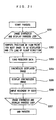
- FIG. 21 shows a process loop of image reproduction according to this conventional technique.
- S201 is a loop in which an image is repeatedly synthesized and displayed.
- a view point and a line-of-sight direction for a traveling path are initially computed.
- the next view point position and line-of-sight direction to be displayed are computed and determined from a relative movement computed at S206, relative to the current view point and line-of-sight direction.
- an image extending in the line-of-sight direction determined at S202 is synthesized from the panoramic image.
- a user views the image displayed at S205 to indicate movement of the view point and the line-of-sight direction in which a visual angle is moved.
- the user can command move forward, move backward, stop, clockwise rotation, counterclockwise rotation, upward rotation, downward rotation, enlargement, contraction, and end.
- this conventional apparatus can predict the next possible view point position and line-of-sight direction to be indicated by the user in order to load a required image in advance, thereby achieving fast display.
- the conventional apparatus repeatedly invokes, for each reproduction, images photographed at a view point position and in a line-of-sight direction dependent on the user's command and synthesizes and displays the images, to provide the user with images that provide him or her with the feeling of being at the site.
- An omnidirectional video output method comprises transmitting image pickup position data representing a service area having omnidirectional images, from a supply center to a terminal device, and transmitting at least view point information of desired view point information and line-of-sight information from the terminal device to the supply center.
- the amount of data in information between the supply center and the terminal device is reduced to increase the reproduction speed, thereby providing users with the feeling of being at the site.
- This configuration also improves the input method for the terminal device to facilitate the operation of inputting the desired traveling path and line of sight.
- the supply center presents image pickup position data for omnidirectional images to the terminal device, which receives, based on the image pickup position data, image information for a desired traveling path determined depending on the desired view point. Accordingly, the user can easily input the desired traveling path and can continuously view only images on the desired traveling path in such a manner that the reproduction time passes smoothly.
- the supply center extracts omnidirectional images from an omnidirectional image position file based on the view point information, subsequently processes the images based on the line-of-sight information, and then transmits only the required image to the terminal device for display. Consequently, the user can enjoy an all-image display that provides users with the feeling of being at the site, regardless of an arithmetic-operation process speed of the terminal device.
- FIGS. 1 to 12 show (Embodiment 1).
- FIG. 1 is an omnidirectional video apparatus according to Embodiment 1.
- An omnidirectional image pickup means 1 photographs omnidirectional images at a view point position to output image data.
- An image pickup position obtaining means 2 obtains positions where the omnidirectional image pickup means 1 picked up the images.
- the images picked up by the omnidirectional image pickup means 1 and the image pickup positions obtained by the image pickup position obtaining means 2 are stored in an omnidirectional image position storage means 3.
- the omnidirectional image position storage means 3 and an image pickup position display means 4 are connected together via a bidirectional communication means 10 so that image pickup positions stored in the omnidirectional image position storage means 3 are displayed on the image pickup position display means 4.
- a user specifies one of the image pickup positions displayed by the image pickup position display means 4, as his or her desired view point position, by inputting it to a view point position indicating means 5.
- the view point position indicating means 5 is connected to an image converting means 6 via a bidirectional communication means 10, and the image converting means 6 invokes from the omnidirectional view point position storage means 3 an image recorded at a position indicated by the view point position indicating means 5 and geometrically converts and rearranges the image, which was photographed in all directions.
- the image converting means 6 is connected to an image processing means 8 via the bidirectional communication means 10, and the image processing means 8 has a line-of-sight indicating means 7 connected thereto for indicating a line-of-sight direction and an angle of view for the image obtained from the image converting means 6.
- the image processing means 8 cuts a partial image out from the image obtained from the image converting means 6 depending on the line-of-sight direction and angle of view specified by the line-of-sight indicating means 7.
- the partial image obtained by the image processing means 8 by cutting out the original image is displayed by the image display means 9.
- the omnidirectional image pickup means 1 and the image pickup position obtaining means 2 are provided in a video sensor device 11 in an arrangement drawing of the entire system shown in FIG. 2.
- the omnidirectional image position storage means 3 and the image converting means 6 are provided in a supply center 12.
- the image pickup position display means 4, the view point position indicating means 5, the line-of-sight indicating means 7, the image processing means 8, and the image display means 9 are provided in a terminal device 13.
- the supply center 12 and the terminal device 13 are connected together via the bidirectional communication means 10 for bidirectional information communication.
- FIG. 2 shows the one supply center 12 and the one terminal device 13, a plurality of supply centers or terminal devices may be connected to the bidirectional communication means 10.
- the video sensor device 11 is configured to move in a direction perpendicular to the direction of an optical axis of a television camera 15 while mounting a mirror 14 and the television camera 15 on a traveling device 17.
- the traveling device 17 moves on a horizontal plane.
- the television camera 15 is installed in such a manner that the optical axis extends in a vertical direction, to pick up an image reflected by the mirror 14.
- the mirror 14 is installed in such a manner that the optical axis of the television camera 15 aligns with the center axis of the mirror 14 so that the image reflected by the mirror 14 can be picked up to obtain an omnidirectional image around the optical axis of the television camera 15 at one time.
- the mirror 14 is a curved surface that is symmetrical with respect to the axis. It may be shaped into a cone or a spherical surface but will be described as having a hyperboloid.
- Reference numeral 14a denotes a cylindrical translucent body for supporting the mirror 14 at a target position. In this embodiment, however, a method for picking up an image extending around a view point position through 360° using the mirror 14, but for example, a fisheye lens may be used for image pickup or the camera may be rotated to synthesize picked-up images, as long as the image can be arranged around the view point position through 360°.
- the video sensor device 11 is used outdoors.
- the television camera 15 can desirably obtain dynamic-range images that are larger than those obtained by normal cameras; a preferable television camera can synthesize images obtained with a normal exposure and a short-time exposure, into one field.
- the video sensor device 11 has a GPS device 16 mounted thereon as the image pickup position obtaining means 2, to obtain global positions of the video sensor device 11.
- the GPS device 16 obtains its own position on the earth (latitude and longitude) via a satellite (not shown).
- a preferable GPS is a differential one that can obtain its own position by detecting its relative position to a certain point the latitude and longitude of which are known.
- FIG. 3 is a view useful in explaining the principle of image pickup of an omnidirectional image.
- Reference numeral 18 denotes a photographing object.
- Reference numeral 19 denotes an image forming plane of the television camera 15.
- Reference numeral 20 is a focal point of the television camera 15.
- Reference numeral 21 denotes a position on the image forming plane 19 where the photographing object 18 is formed into an image.
- Reference numeral 22 denotes an area of the formed image obtained by image pickup in all directions.
- Coordinate axes X and Y are set on a plane parallel with the image forming plane 19 using a focal point 20 of the television camera 20 as an origin.
- a Z axis is set in a direction perpendicular to the image forming plane 19 using the focal point 20 of the television camera 15 as an origin.
- the center axis of the mirror 14 aligns with the Z axis. In this case, an image of the photographing object 18 has its direction changed by the mirror 14 and passes through the focal point 20 of the television camera before reaching an image forming position 21 on the image forming plane 19.
- the formed image 22 corresponds to an image observed from the virtual focal point 23 through an azimuth of 360° around the X axis.
- An elevation direction at the virtual focal point 23 from an XY plane varies depending on the angle of view of the television camera 15.
- FIG. 4 An example of an omnidirectional image is shown in FIG. 4.
- Reference numeral 24 denotes an omnidirectional image that is circular.
- a radial direction of the omnidirectional image 24 is denoted by R and its circumferential direction is denoted by ⁇
- the radial direction R corresponds to the direction of the elevation angle of the line of sight from the virtual focal point 23 in FIG. 3
- the circumferential direction ⁇ corresponds to the direction of the azimuth of the line of sight from the virtual focal point 23 in FIG. 3.
- FIG. 5 is an image showing a traveling path of the video sensor device 11.
- the arrow shows a traveling direction, indicating that the device starts from point A and moves in the order of A, B, C, D, E, F, C, D, and A.
- Reference numerals 25a, 25b, and 25c denote the positions of buildings located on the path.
- the video sensor device 11 While moving along the traveling path shown in FIG. 5, the video sensor device 11 uses the television camera 15 and the GPS device 16 mounted thereon to obtain an omnidirectional image and positional information and then transmits them to the supply center 12.
- the transmission of the omnidirectional image and positional information from the video sensor device 11 to the supply center 12 can be implemented by using radio or wired communication or recording them on a recording medium such as a DVD.
- FIG. 6 is a schematic view showing how omnidirectional images and positions are recorded in the supply center 12.
- reference numeral 26 denotes an omnidirectional image position file in which are recorded omnidirectional images photographed at the same time and their positions which are allocated with record numbers.
- reference numeral 26 denotes an omnidirectional image position file in which are recorded omnidirectional images photographed at the same time and their positions which are allocated with record numbers.
- the omnidirectional image and positional information are recorded together is shown, but they may be individually recorded and have the same record number attached thereto.
- the bidirectional communication means 10 starts communication between the supply center 12 and the terminal device 13 in response to a command from the terminal device 13.
- the omnidirectional image position storage means 3 has the omnidirectional image position file 26 recorded therein as shown in FIG. 6. First, positional information and a record number are obtained, and all image pickup positions are displayed on the image pickup position display means 4 of the terminal device 13 via the bidirectional communication means 10.
- FIG. 7 shows all image pickup positions displayed on the image pickup position display means 4. Dotted lines in FIG. 7 show the image pickup position.
- the image pickup position display means 4 displays the latitude and longitude information on a reduced scale. Characters A, B, C, D, E, and F in FIG. 7 indicating positions are for explanation only and are not displayed on the image pickup position display means 4.
- the user who has checked all the image pickup positions displayed on the image pickup position display means 4 at (step 1-1), specifies the user's desired observation path from all the image pickup positions using the view point position indicating means 5.
- FIG. 8 shows a result of the indication of the observation path using the view point position indicating means 5. This figure shows, for example, a result of the indication of a path passing through the points A, B, C, and D.
- the continuous observation path is selected using the view point position indicating means 5, but a discontinuous observation path such as A-B and E-F may be selected.
- the terminal device 13 recognizes all the image pickup positions and displays them on a display screen of the terminal device 13 in the format shown in FIG. 7.
- the user uses as an input device a touch panel mounted in such a manner as to overlap the display screen, to touch via the touch panel the display screen of all the image pickup positions at positions corresponding to the observation path, thereby inputting the indicated positions.
- the user inputs the observation path from a keyboard of the terminal device 13.
- Record numbers corresponding to the positions of the observation path indicated by the view point position indicating means 5 at (Step 1-2) are arranged in the order of observation and then transmitted to the image converting means 6 via the bidirectional communication means 10.
- Omnidirectional images corresponding to the record numbers transmitted from the view point position indicating means 5 at (Step 1-3) are invoked from the omnidirectional image position storage means 3 and transmitted to the image converting means 6.
- the omnidirectional images transmitted to the image converging means 6 at (Step 1-4) are converted.
- the process method executed by the image converting means 6 will be explained with reference to FIGS. 3, 4, 9, and 10.
- FIG. 9 shows an image into which the omnidirectional image 24 in FIG. 4 has been converted and which is assumed to be observed from the virtual focal point 23 shown in FIG. 3. This image is hereafter referred to as a "expanded image 27".
- An X direction of the expanded image 27 corresponds to an azimuth direction ⁇ around the Z axis observed from the virtual focal point 23, thereby allowing an image extending through an azimuth of 360° to be obtained.
- a Y direction of the image corresponds to the elevation direction R observed from the virtual focal point 23.
- the image converting means 6 invokes the omnidirectional images 24 corresponding to the record numbers transmitted from the view point position indicating means 5 and converts them into the expanded images 27.
- the image converting means 6 then rearranges the expanded images 27 in the order of the observation path specified by the view point position indicating means 5.
- FIG. 10 shows a sequence of the expanded images 27 thus obtained.
- a expanded image file 28 having the expanded images 27 arranged in the order of the observation is created and transmitted to the image processing means 8 via the bidirectional communication means 10.
- FIG. 11 shows an example of an image obtained by the image processing means 8 by cutting a partial area out from the expanded image 27 in FIG. 9. This image is hereafter referred to as a "window image 29".
- the window image 29 in FIG. 11 is obtained by specifying a line-of-sight direction, that is, an elevation angle and an azimuth and cutting the partial area out from the expanded image 27 in FIG. 9.
- the size of the cut-out area corresponds to the angle of view from the observation point.
- Step 1-6 (Step 1-6) will be explained below in detail.
- the image processing means 8 uses preset predetermined elevation angle and azimuth to create a first window image 29 from the expanded image file 28 in FIG. 10 transmitted via the bidirectional communication means 10 at (step 1-5), and then displays this window image on the image display means 9.
- FIG. 12 is a schematic view of the sight indicating means 7.
- FIG. 12 is a schematic view of the sight indicating means 7.
- reference numerals 30a and 30b denote elevation angle indicating buttons
- reference numerals 31a and 31b denote azimuth indicating buttons
- 32a and 32b denote angle of view indicating buttons.
- Step 1-6-(2) the line-of-sight direction and angle of view changed by the line-of-sight indicating means 7 are transmitted to the image processing means 8, and the cut-out area is changed for the next expanded image to create the window image 29, which is then displayed on the image display means 9.
- Step 1-6-(3) the cut-out area is changed for the next expanded image to create the window image 29, which is then displayed on the image display means 9.
- the positions at which the omnidirectional image 24 was photographed are presented to the user beforehand so that an image free from information on unwanted paths and containing only a required view point position can be created and transmitted. Consequently, the images of all the photographed areas need not be transmitted to thereby reduce the amount of communicated data and thus communication costs. Additionally, the user can display images promptly to reduce the amount of waiting time.
- FIGS. 13 and 14 show (Embodiment 2).
- FIG. 13 shows an omnidirectional video apparatus according to (Embodiment 2).
- the omnidirectional image pickup means 1, the image pickup position obtaining means 2, the omnidirectional image position storage means 3, and the image pickup position display means 4 are the same as those of (Embodiment 1).
- the terminal device 13 inputs a desired view point and then processes data received from the supply center 12 depending on its desired line of sight to obtain a target display screen.
- (Embodiment 2) differs from (Embodiment 1) in that not only the desired view point but also a line-of-sight direction are specified and communicated to the supply center 12 to obtain the target display screen without the need to reprocess data returned to the terminal device 13 from the supply center 12.
- An output from the line-of-sight vector indicating means 33 is input to an image extracting and converting means 34 via the bidirectional communication means 10.
- the image extracting and converting means 34 provided in the supply center 12 invokes the omnidirectional image 24 from the omnidirectional image position file 26 of the omnidirectional image position storage means 3, the omnidirectional image 24 having been recorded at the view point position indicated by the line-of-sight vector indicating means 33.
- the image extracting and converting means 34 then generates the window image 29 photographed in the line-of-sight direction indicated by the line-of-sight vector indicating means 33.
- a sequence of the window images 29 created by the image extracting and converting means 34 are compressed by the image compressing means 35 and transmitted via the bidirectional communication means 10 to the terminal device 13, where an image recovering means 36 recovers the signal transmitted from the image compressing means 35.
- the sequence of images recovered by the image recovering means 36 are displayed on the image display means 9.
- (Embodiment 2) differs from (Embodiment 1) in that the supply center 12 has the omnidirectional image position storage means 3, the image extracting and converting means 34, and the image compressing means 35 and in that the terminal device 13 has the image pickup position display means 4, the line-of-sight vector indicating means 33, the image recovering means 36, and the image display means 9.
- the omnidirectional image position storage means 3 has the omnidirectional image position file 26 shown in FIG. 6, recorded therein. First, positional information and record numbers are taken out from the storage means, and the image pickup positions are displayed on the image pickup position display means 4 of the terminal device 13 via the bidirectional communication means 10. The image pickup positions displayed by the image pickup position display means 4 are similar to those in FIG. 7.
- the user specifies his or her desired observation path and line-of-sight directions for each observation path, from all the image pickup positions, using the line-of-sight vector indicating means 33.
- FIG. 14 shows the observation path and line-of-sight directions indicated using the line-of-sight vector indicating means 33.
- the observation path is shown by solid arrows 41, and the line-of-sight directions are denoted by thick white arrows 42.
- the indication of the observation path is input from the display screen or keyboard (not shown) of the terminal device 13 in the same manner as in (Embodiment 1).
- the observation path and line-of-sight directions indicated by the line-of-sight vector indicating means 33, that is, the elevation angle and the azimuth are transmitted to the image extracting and converting means 34 via the bidirectional communication means 10.
- the image extracting and converting means 34 invokes the omnidirectional image 24 from the omnidirectional image position storage means 3, the omnidirectional image 24 corresponding to the observation path transmitted from the line-of-sight vector indicating means 33.
- the image extracting and converting means 34 uses the omnidirectional image 24 obtained at (Step 2-4) and the line-of-sight directions obtained at (Step 2-3) to create the window images 29 shown in FIG. 11.
- the expanded images 27 shown in FIG. 9 need not necessarily be created but the window images 29 are desirably created directly from the omnidirectional images 24.
- the created window images 29 are rearranged along the observation path and then transmitted to the image compressing means 35.
- the image compressing means 35 compresses the sequence of the window images 29 obtained at (Step 2-5) to reduce the amount of signals. Since the window images 29 have been rearranged in the order of the observation path, for example, the order of display, the image compression may be video compression, for example, that based on the MPEG.
- the compressed signal is transmitted to the image recovering means 36 of the terminal device 13 via the bidirectional communication means 10.
- the image recovering means 36 stores the images transmitted from the image compressing means 35 in a primary buffer (not shown) and recovers and transmits them to the image display means 9 for display.
- the images are compressed before transmission to reduce the amount of communicated data.
- the user (the terminal device 13) must execute only the process of recovering the images and need not execute conversions based on an image converting process, so that the images are displayed at equal time intervals to provide the user with the feeling of being at the site without compromising smooth display or reproduction.
- FIGS. 15 to 17 show (Embodiment 3).
- FIG. 15 shows an omnidirectional video apparatus according to (Embodiment 3).
- (Embodiment 3) is the same as (Embodiment 2) except that the image pickup position display means 4 of the terminal device 13 is replaced with a map data storage means 37 and a synthesizing position display means 38.
- the map data storage means 37 has map data for an area photographed by the omnidirectional image pickup means 1, previously written thereto.
- the synthesizing position display means 38 is connected to the omnidirectional image position storage means 3 of the supply center 12 via the bidirectional communication means 10 to display the photographing positions stored in the omnidirectional image position storage means 3 as in (Embodiment 1) and (Embodiment 2), while synthesizing and displaying the map information stored in the map data storage means 37, on the same screen.
- FIG. 16 shows a display format for the synthesizing position display means 38.
- reference numerals 25a, 25b, and 25c denote the positions of the buildings on the path. In this manner, not only the traveling path is displayed but also the map information such as the locations of buildings are added and displayed based on the map data.
- FIG. 17 shows an observation path and a line-of-sight direction indicated by the view point vector indicating means 33.
- the arrows 41 in FIG. 17 denote the observation path
- the thick white arrows 42 denote the line-of-sight directions. If, for example, the user desires to observe the buildings 25a, 25b, and 25c, since their positions have been confirmed in advance, the user selects an observation path passing through the points A, B, C, and F and indicates the line-of-sight directions toward the buildings 25a, 25b, and 25c.
- the positions where the omnidirectional images were photographed and the map information are synthesized and displayed to enable the user to recognize environments of the photographing positions beforehand to accurately indicate an observation path and a line-of-sight direction depending on the user's tastes.
- the map data storage means 37 is provided inside the terminal device 13, but similar effects are clearly obtained by providing it inside the supply center 12 or invoking the map data storage means 37 installed in another device (not shown) connected to the bidirectional communication device.
- FIGS. 18 to 20 shows (Embodiment 4).
- (Embodiment 4) is the same as (Embodiment 1) except that the map data storage means 37 and the synthesizing position display means 38 replace the image pickup position display means 4 according to (Embodiment 1) shown in FIG. 1 and that an object specifying means 39 and a view point position computing means 40 replace the view point position indicating means 5.
- the map data storage means 37 and the synthesizing position display means 38 are the same as those in (Embodiment 3).
- the object specifying means 39 is an input device for specifying only a desired object of the objects on all the image pickup paths displayed by the synthesizing position display means 38.
- a view point position computing means 40 computes an optimal path from the position of the object specified by the object specifying means 39.
- the synthesizing position display means 38 invokes from the map data storage means 37 map data for an area photographed by the omnidirectional image pickup means 1, and synthesizes and displays them.
- a path diagram displayed by the synthesizing position display means 38 and having the additional map data is similar to that in FIG. 16.
- reference numerals 25a, 25b, and 25c denote the positions of the buildings on the path. In this manner, not only the traveling path is displayed but also the map information such as the locations of buildings are added and displayed based on the map data.
- the user uses the object specifying means 39 to specify only a desired object on the path of the photographing positions displayed on the synthesizing position display means 38.
- FIG. 19 shows a result of specification of a plurality of objects by means of the object specifying means 39.
- the thick white arrows denote the specified objects; in FIG. 19, the buildings 25a and 25c have been specified.
- the view point position computing means 40 in FIG. 18 automatically computes a path for observing the specified buildings 25a and 25c as shown in FIG. 19.
- FIG. 20 shows a result of display of the result of the computation of the observation path.
- the path is shown by an arrow 44.
- To compute the path for example, all paths joining the buildings 25a and 25c in FIG. 19 together and the shortest of them is determined as the observation path.
- a different method may be used to compute the path as long as it can compute a path between a plurality of objects.
- Step 4-2-(2) Since the observation path has been established at (Step 4-2-(2)), the subsequent steps are similar to (step 1-3) to (Step 1-6) in (Embodiment 1).
- the positions where the omnidirectional images 24 were photographed and the map information are synthesized and displayed to enable the user to recognize environments of the photographing positions beforehand to accurately indicate an observation path depending on the user's tastes.
- the path can be automatically created simply by specifying the user's desired place, so that images of the user's desired place can be simply reproduced without the need to input the view point position.
- the observation path is automatically computed while the line-of-sight direction is indicated by the user, but the direction of the object relative to the observation path can be easily estimated from this path.
- the view point position computing means 40 can be used to mathematically obtain the observation path and the line-of-sight direction. In that case, the process will be similar to (Step 2-3) and (Step 2-7) in (Embodiment 2).
- the terminal device 13 has an computation means for computing an optimal observation path joining each view point with the position of the object specified by the object specifying means 39 to output view point information and estimating the direction of the object relative to the observation path to output line-of-sight information.
- the supply center 12 has the image extracting and converting means 34 for invoking required image data from the omnidirectional image position storage means 3 to convert them into expanded images based on the view point information and line-of-sight information indicated by the computation means via the bidirectional communication means 10, and processing the expanded images 27 depending on the line-of-sight information.
- the terminal device 13 has the image display means 9 for displaying as an image a signal received from the image extracting and converting means 34 via the bidirectional communication means 10.
Landscapes
- Engineering & Computer Science (AREA)
- Multimedia (AREA)
- Signal Processing (AREA)
- Physics & Mathematics (AREA)
- General Physics & Mathematics (AREA)
- Human Computer Interaction (AREA)
- Theoretical Computer Science (AREA)
- General Engineering & Computer Science (AREA)
- Databases & Information Systems (AREA)
- Computer Hardware Design (AREA)
- Computer Graphics (AREA)
- Software Systems (AREA)
- Processing Or Creating Images (AREA)
- Two-Way Televisions, Distribution Of Moving Picture Or The Like (AREA)
- Closed-Circuit Television Systems (AREA)
- Television Signal Processing For Recording (AREA)
- Stereoscopic And Panoramic Photography (AREA)
- Image Processing (AREA)
- Studio Circuits (AREA)
- Testing, Inspecting, Measuring Of Stereoscopic Televisions And Televisions (AREA)
Applications Claiming Priority (3)
| Application Number | Priority Date | Filing Date | Title |
|---|---|---|---|
| JP11179106A JP2001008232A (ja) | 1999-06-25 | 1999-06-25 | 全方位映像出力方法と装置 |
| JP17910699 | 1999-06-25 | ||
| PCT/JP2000/004002 WO2001005154A1 (fr) | 1999-06-25 | 2000-06-19 | Procede de sortie video tous azimuts et dispositif associe |
Publications (2)
| Publication Number | Publication Date |
|---|---|
| EP1117256A1 true EP1117256A1 (de) | 2001-07-18 |
| EP1117256A4 EP1117256A4 (de) | 2005-12-28 |
Family
ID=16060138
Family Applications (1)
| Application Number | Title | Priority Date | Filing Date |
|---|---|---|---|
| EP00937308A Withdrawn EP1117256A4 (de) | 1999-06-25 | 2000-06-19 | Verfahren und gerät für rundumbildausgabe |
Country Status (6)
| Country | Link |
|---|---|
| US (1) | US6762789B1 (de) |
| EP (1) | EP1117256A4 (de) |
| JP (1) | JP2001008232A (de) |
| KR (1) | KR20010072917A (de) |
| CN (1) | CN1219402C (de) |
| WO (1) | WO2001005154A1 (de) |
Cited By (7)
| Publication number | Priority date | Publication date | Assignee | Title |
|---|---|---|---|---|
| EP1519582A1 (de) * | 2002-06-28 | 2005-03-30 | Sharp Kabushiki Kaisha | Bilddatenablieferungssystem, bilddatensendeeinrichtung dafür und bilddatenempfangseinrichtung dafür |
| US7831086B2 (en) | 2002-06-03 | 2010-11-09 | Sony Corporation | Image processing device and method, program, program recording medium, data structure, and data recording medium |
| EP2779114A1 (de) * | 2013-03-11 | 2014-09-17 | Dai Nippon Printing Co., Ltd. | Vorrichtung für interaktiven virtuellen rundgang |
| CN107979773A (zh) * | 2016-10-25 | 2018-05-01 | 三星电子株式会社 | 电子设备及其控制方法 |
| GB2556344A (en) * | 2016-10-17 | 2018-05-30 | Nctech Ltd | Camera controller |
| US11087480B2 (en) | 2016-08-03 | 2021-08-10 | Sony Corporation | Image processing apparatus and image processing method |
| US12101886B2 (en) | 2019-02-28 | 2024-09-24 | Sony Group Corporation | Electronic apparatus and substrate |
Families Citing this family (52)
| Publication number | Priority date | Publication date | Assignee | Title |
|---|---|---|---|---|
| WO2002078344A1 (en) * | 2001-03-26 | 2002-10-03 | Hyun-Gi An | Method for processing moving pictures responding to user's action |
| JP2003069990A (ja) * | 2001-06-13 | 2003-03-07 | Usc Corp | 遠隔映像認識システム |
| JP3951695B2 (ja) | 2001-12-11 | 2007-08-01 | ソニー株式会社 | 画像配信システムおよび方法、画像配信装置および方法、画像受信装置および方法、記録媒体、並びにプログラム |
| JP4010444B2 (ja) * | 2002-02-28 | 2007-11-21 | シャープ株式会社 | 全方位監視制御システム、全方位監視制御方法および全方位監視制御プログラム |
| JP4012749B2 (ja) * | 2002-03-14 | 2007-11-21 | 国立大学法人 奈良先端科学技術大学院大学 | 遠隔操縦システム |
| JP4055201B2 (ja) * | 2002-04-12 | 2008-03-05 | ソニー株式会社 | サービス提供システム、情報処理装置および方法、記録媒体、並びにプログラム |
| WO2004004363A1 (ja) * | 2002-06-28 | 2004-01-08 | Sharp Kabushiki Kaisha | 画像符号化装置、画像送信装置および画像撮影装置 |
| JP2004072694A (ja) * | 2002-08-09 | 2004-03-04 | Sony Corp | 情報提供システムおよび方法、情報提供装置および方法、記録媒体、並びにプログラム |
| WO2004084542A1 (ja) * | 2003-03-20 | 2004-09-30 | Seijiro Tomita | パノラマ画像生成方法及びその装置並びにこれらの方法・装置を用いた監視システム |
| JP4141986B2 (ja) * | 2003-07-17 | 2008-08-27 | セイコーエプソン株式会社 | 視線誘導情報表示装置および視線誘導情報表示プログラム |
| CN100353748C (zh) * | 2004-01-05 | 2007-12-05 | 仁宝电脑工业股份有限公司 | 利用实时影像为背景撷取对象的方法 |
| TWI253292B (en) * | 2004-03-23 | 2006-04-11 | Yu-Lin Chiang | Pano camera monitoring and tracking system and method thereof |
| JP4207883B2 (ja) * | 2004-03-24 | 2009-01-14 | セイコーエプソン株式会社 | 視線誘導度算出システム |
| JP2005327220A (ja) * | 2004-05-17 | 2005-11-24 | Sharp Corp | イラスト図作成装置、イラスト図作成方法、制御プログラムおよび可読記録媒体 |
| KR100679740B1 (ko) | 2004-06-25 | 2007-02-07 | 학교법인연세대학교 | 시점 선택이 가능한 다시점 동영상 부호화/복호화 방법 |
| KR100739686B1 (ko) * | 2004-08-13 | 2007-07-13 | 경희대학교 산학협력단 | 영상 코딩 방법, 코딩 장치, 영상 디코딩 방법 및 디코딩장치 |
| JP2006262253A (ja) * | 2005-03-18 | 2006-09-28 | Sanyo Electric Co Ltd | 画像転送装置 |
| JP2006333132A (ja) * | 2005-05-26 | 2006-12-07 | Sony Corp | 撮像装置及び撮像方法、プログラム、プログラム記録媒体並びに撮像システム |
| JP4841864B2 (ja) * | 2005-05-27 | 2011-12-21 | 寺田軌道株式会社 | 作業計画立案システム、画像表示装置およびプログラム |
| CN101472190B (zh) * | 2007-12-28 | 2013-01-23 | 华为终端有限公司 | 多视角摄像及图像处理装置、系统 |
| WO2009131287A1 (en) * | 2008-04-23 | 2009-10-29 | Lg Electronics Inc. | Method for encoding and decoding image of ftv |
| JP4787292B2 (ja) * | 2008-06-16 | 2011-10-05 | 富士フイルム株式会社 | 全方位撮像装置 |
| JP5031016B2 (ja) * | 2009-12-07 | 2012-09-19 | 株式会社リコー | 画像処理装置、画像処理方法およびプログラム |
| WO2011114610A1 (ja) * | 2010-03-18 | 2011-09-22 | パナソニック株式会社 | 全方位画像処理装置および全方位画像処理方法 |
| US20120208168A1 (en) * | 2010-10-11 | 2012-08-16 | Teachscape, Inc. | Methods and systems relating to coding and/or scoring of observations of and content observed persons performing a task to be evaluated |
| JP5742210B2 (ja) * | 2010-12-22 | 2015-07-01 | ソニー株式会社 | 撮像装置、画像処理装置、画像処理方法およびプログラム |
| USD698363S1 (en) | 2010-12-28 | 2014-01-28 | Sony Corporation | Display screen with a graphical user interface |
| KR101449748B1 (ko) * | 2011-08-18 | 2014-10-13 | 엘지디스플레이 주식회사 | 입체영상 디스플레이장치 및 그 구동 방법 |
| EP2754005A4 (de) * | 2011-09-08 | 2015-04-22 | Intel Corp | Auf augenverfolgung basierende positionsbestimmung für audiovisuelle wiedergabe |
| JP5870618B2 (ja) * | 2011-10-21 | 2016-03-01 | 大日本印刷株式会社 | 自由視点映像表示装置 |
| JP5845819B2 (ja) * | 2011-11-02 | 2016-01-20 | 大日本印刷株式会社 | 動画提示装置 |
| JP5920708B2 (ja) * | 2012-02-29 | 2016-05-18 | 国立大学法人名古屋大学 | 多視点映像ストリーム視聴システムおよび方法 |
| JP5861499B2 (ja) * | 2012-03-01 | 2016-02-16 | 大日本印刷株式会社 | 動画提示装置 |
| US9824721B2 (en) * | 2013-01-16 | 2017-11-21 | Mitsuo Hayashi | Video generation device, video generation program, and video generation method |
| JP6060817B2 (ja) * | 2013-05-31 | 2017-01-18 | 株式会社Jvcケンウッド | 経路決定装置、経路決定方法、及び経路決定プログラム |
| RU2650493C2 (ru) * | 2013-06-07 | 2018-04-16 | Дап Риэлайз Инк. | Система распределения видео в реальном времени |
| US10204658B2 (en) | 2014-07-14 | 2019-02-12 | Sony Interactive Entertainment Inc. | System and method for use in playing back panorama video content |
| US20160182822A1 (en) * | 2014-12-19 | 2016-06-23 | Sony Corporation | System, method, and computer program product for determiing a front facing view of and centering an omnidirectional image |
| US11089280B2 (en) | 2016-06-30 | 2021-08-10 | Sony Interactive Entertainment Inc. | Apparatus and method for capturing and displaying segmented content |
| WO2018004936A1 (en) * | 2016-06-30 | 2018-01-04 | Sony Interactive Entertainment Inc. | Apparatus and method for providing and displaying content |
| CN106445129A (zh) * | 2016-09-14 | 2017-02-22 | 乐视控股(北京)有限公司 | 全景图像信息显示方法、装置及系统 |
| US10999602B2 (en) | 2016-12-23 | 2021-05-04 | Apple Inc. | Sphere projected motion estimation/compensation and mode decision |
| US11259046B2 (en) | 2017-02-15 | 2022-02-22 | Apple Inc. | Processing of equirectangular object data to compensate for distortion by spherical projections |
| US10924747B2 (en) | 2017-02-27 | 2021-02-16 | Apple Inc. | Video coding techniques for multi-view video |
| CN108882018B (zh) * | 2017-05-09 | 2020-10-20 | 阿里巴巴(中国)有限公司 | 虚拟场景中的视频播放、数据提供方法、客户端及服务器 |
| US11093752B2 (en) * | 2017-06-02 | 2021-08-17 | Apple Inc. | Object tracking in multi-view video |
| US10754242B2 (en) | 2017-06-30 | 2020-08-25 | Apple Inc. | Adaptive resolution and projection format in multi-direction video |
| CN107396085A (zh) * | 2017-08-24 | 2017-11-24 | 三星电子(中国)研发中心 | 一种全视点视频图像的处理方法及系统 |
| JP7132730B2 (ja) * | 2018-03-14 | 2022-09-07 | キヤノン株式会社 | 情報処理装置および情報処理方法 |
| US11284054B1 (en) * | 2018-08-30 | 2022-03-22 | Largo Technology Group, Llc | Systems and method for capturing, processing and displaying a 360° video |
| JPWO2020184188A1 (de) * | 2019-03-08 | 2020-09-17 | ||
| JP7423251B2 (ja) * | 2019-10-25 | 2024-01-29 | キヤノン株式会社 | 情報処理装置、情報処理方法、及びプログラム |
Citations (2)
| Publication number | Priority date | Publication date | Assignee | Title |
|---|---|---|---|---|
| US5396583A (en) * | 1992-10-13 | 1995-03-07 | Apple Computer, Inc. | Cylindrical to planar image mapping using scanline coherence |
| US5611025A (en) * | 1994-11-23 | 1997-03-11 | General Electric Company | Virtual internal cavity inspection system |
Family Cites Families (8)
| Publication number | Priority date | Publication date | Assignee | Title |
|---|---|---|---|---|
| JP3352475B2 (ja) | 1992-10-13 | 2002-12-03 | 有限会社ジーティービー | 画像表示装置 |
| US5920337A (en) * | 1994-12-27 | 1999-07-06 | Siemens Corporate Research, Inc. | Omnidirectional visual image detector and processor |
| JPH0962861A (ja) | 1995-08-21 | 1997-03-07 | Matsushita Electric Ind Co Ltd | パノラマ映像装置 |
| JPH09161096A (ja) | 1995-12-06 | 1997-06-20 | Matsushita Electric Ind Co Ltd | 3次元画像表示制御装置 |
| US6445807B1 (en) * | 1996-03-22 | 2002-09-03 | Canon Kabushiki Kaisha | Image processing method and apparatus |
| US5760826A (en) * | 1996-05-10 | 1998-06-02 | The Trustees Of Columbia University | Omnidirectional imaging apparatus |
| JP3566530B2 (ja) | 1998-01-08 | 2004-09-15 | 日本電信電話株式会社 | 空間散策映像表示方法及び空間内オブジェクト検索方法及び空間内オブジェクト抽出方法及びそれらの装置及びそれらの方法を記録した記録媒体 |
| US6304285B1 (en) * | 1998-06-16 | 2001-10-16 | Zheng Jason Geng | Method and apparatus for omnidirectional imaging |
-
1999
- 1999-06-25 JP JP11179106A patent/JP2001008232A/ja active Pending
-
2000
- 2000-06-19 US US09/763,243 patent/US6762789B1/en not_active Expired - Lifetime
- 2000-06-19 CN CNB008011974A patent/CN1219402C/zh not_active Expired - Lifetime
- 2000-06-19 KR KR1020017002335A patent/KR20010072917A/ko not_active Application Discontinuation
- 2000-06-19 WO PCT/JP2000/004002 patent/WO2001005154A1/ja not_active Application Discontinuation
- 2000-06-19 EP EP00937308A patent/EP1117256A4/de not_active Withdrawn
Patent Citations (2)
| Publication number | Priority date | Publication date | Assignee | Title |
|---|---|---|---|---|
| US5396583A (en) * | 1992-10-13 | 1995-03-07 | Apple Computer, Inc. | Cylindrical to planar image mapping using scanline coherence |
| US5611025A (en) * | 1994-11-23 | 1997-03-11 | General Electric Company | Virtual internal cavity inspection system |
Non-Patent Citations (3)
| Title |
|---|
| ONOE Y ET AL: "Telepresence by Real-Time View-Dependent Image Generation from Omnidirectional Video Streams" COMPUTER VISION AND IMAGE UNDERSTANDING, ACADEMIC PRESS, SAN DIEGO, CA, US, vol. 71, no. 2, August 1998 (1998-08), pages 154-165, XP004448860 ISSN: 1077-3142 * |
| See also references of WO0105154A1 * |
| TEODOSIO L A; MILLS M: "Panoramic overviews for navigating real-world scenes" PROCEEDINGS OF FIRST ACM INTERNATIONAL CONFERENCE ON MULTIMEDIA, 3 August 1993 (1993-08-03), pages 359-364, XP002348230 Anaheim, USA * |
Cited By (15)
| Publication number | Priority date | Publication date | Assignee | Title |
|---|---|---|---|---|
| US7831086B2 (en) | 2002-06-03 | 2010-11-09 | Sony Corporation | Image processing device and method, program, program recording medium, data structure, and data recording medium |
| EP1519582A4 (de) * | 2002-06-28 | 2007-01-31 | Sharp Kk | Bilddatenablieferungssystem, bilddatensendeeinrichtung dafür und bilddatenempfangseinrichtung dafür |
| US7734085B2 (en) | 2002-06-28 | 2010-06-08 | Sharp Kabushiki Kaisha | Image data delivery system, image data transmitting device thereof, and image data receiving device thereof |
| EP1519582A1 (de) * | 2002-06-28 | 2005-03-30 | Sharp Kabushiki Kaisha | Bilddatenablieferungssystem, bilddatensendeeinrichtung dafür und bilddatenempfangseinrichtung dafür |
| EP2779114A1 (de) * | 2013-03-11 | 2014-09-17 | Dai Nippon Printing Co., Ltd. | Vorrichtung für interaktiven virtuellen rundgang |
| US11087480B2 (en) | 2016-08-03 | 2021-08-10 | Sony Corporation | Image processing apparatus and image processing method |
| GB2556344A (en) * | 2016-10-17 | 2018-05-30 | Nctech Ltd | Camera controller |
| US10904431B2 (en) | 2016-10-17 | 2021-01-26 | Nctech Ltd | Camera controller |
| EP3316119A1 (de) * | 2016-10-25 | 2018-05-02 | Samsung Electronics Co., Ltd. | Elektronische vorrichtung und steuerungsverfahren dafür |
| US10552990B2 (en) | 2016-10-25 | 2020-02-04 | Samsung Electronics Co., Ltd. | Electronic apparatus and control method thereof |
| KR20180045359A (ko) * | 2016-10-25 | 2018-05-04 | 삼성전자주식회사 | 전자장치 및 그 제어방법 |
| CN107979773A (zh) * | 2016-10-25 | 2018-05-01 | 三星电子株式会社 | 电子设备及其控制方法 |
| CN107979773B (zh) * | 2016-10-25 | 2021-12-28 | 三星电子株式会社 | 电子设备及其控制方法 |
| KR102561860B1 (ko) | 2016-10-25 | 2023-08-02 | 삼성전자주식회사 | 전자장치 및 그 제어방법 |
| US12101886B2 (en) | 2019-02-28 | 2024-09-24 | Sony Group Corporation | Electronic apparatus and substrate |
Also Published As
| Publication number | Publication date |
|---|---|
| WO2001005154A8 (fr) | 2001-03-29 |
| JP2001008232A (ja) | 2001-01-12 |
| CN1315114A (zh) | 2001-09-26 |
| KR20010072917A (ko) | 2001-07-31 |
| EP1117256A4 (de) | 2005-12-28 |
| US6762789B1 (en) | 2004-07-13 |
| WO2001005154A1 (fr) | 2001-01-18 |
| CN1219402C (zh) | 2005-09-14 |
Similar Documents
| Publication | Publication Date | Title |
|---|---|---|
| US6762789B1 (en) | Omnidirectional video output method and apparatus | |
| KR100651508B1 (ko) | 증강현실을 이용한 지역 정보 제공 방법 및 이를 위한지역 정보 서비스 시스템 | |
| JP4098808B2 (ja) | 遠隔映像表示方法、映像取得装置及びその方法とそのプログラム | |
| US11310459B2 (en) | Image capturing device, image capturing system, image processing method, and recording medium | |
| EP2302322B1 (de) | Verfahren und Vorrichtung zur Bereitstellung von standortbasierten Diensten mittels Sensor und Bilderkennung in einem tragbaren Endgerät | |
| US11956547B2 (en) | Omnidirectional camera system with improved point of interest selection | |
| KR20090000186A (ko) | 증강현실을 이용한 관심 지점 표시 장치 및 방법 | |
| EP2413104B1 (de) | Vorrichtung und Verfahren zur Straßensichtbereitstellung | |
| US20190289206A1 (en) | Image processing apparatus, image capturing system, image processing method, and recording medium | |
| US20240087157A1 (en) | Image processing method, recording medium, image processing apparatus, and image processing system | |
| US11250540B2 (en) | Image processing apparatus, image capturing system, image processing method, and recording medium | |
| US11102448B2 (en) | Image capturing apparatus, image processing system, image processing method, and recording medium | |
| KR20110070210A (ko) | 위치 감지 센서와 방향 감지 센서를 이용하여 증강현실 서비스를 제공하기 위한 이동단말기 및 방법 | |
| EP3151541B1 (de) | Bildverwaltungssystem, bildkommunikationssystem, verfahren zur steuerung der anzeige eines aufgenommenen bildes und trägeranordnung | |
| JP2008301230A (ja) | 撮像システム及び撮像装置 | |
| US11700455B2 (en) | Image capturing device, image communication system, and method for display control | |
| US11533430B2 (en) | Image capturing device with display control, image communication system, and method for display control, and recording medium | |
| EP4436190A1 (de) | Anzeigeendgerät, kommunikationssystem und anzeigeverfahren | |
| US20240323538A1 (en) | Display terminal, communication system, display method, and recording medium | |
| EP4436191A1 (de) | Anzeigeendgerät, kommunikationssystem, anzeigeverfahren und trägermittel | |
| JP2010165081A (ja) | 表示装置、立体コンテンツ生成システム、立体コンテンツ生成装置、及び、立体コンテンツ生成方法 | |
| JP2010028282A (ja) | カメラおよび座標算出プログラム | |
| JP2004341742A (ja) | 施設情報表示装置 |
Legal Events
| Date | Code | Title | Description |
|---|---|---|---|
| PUAI | Public reference made under article 153(3) epc to a published international application that has entered the european phase |
Free format text: ORIGINAL CODE: 0009012 |
|
| AK | Designated contracting states |
Kind code of ref document: A1 Designated state(s): AT BE CH CY DE DK ES FI FR GB GR IE IT LI LU MC NL PT SE |
|
| AX | Request for extension of the european patent |
Free format text: AL;LT;LV;MK;RO;SI |
|
| 17P | Request for examination filed |
Effective date: 20010606 |
|
| RBV | Designated contracting states (corrected) |
Designated state(s): DE FR GB |
|
| A4 | Supplementary search report drawn up and despatched |
Effective date: 20051116 |
|
| 17Q | First examination report despatched |
Effective date: 20071031 |
|
| STAA | Information on the status of an ep patent application or granted ep patent |
Free format text: STATUS: THE APPLICATION IS DEEMED TO BE WITHDRAWN |
|
| 18D | Application deemed to be withdrawn |
Effective date: 20080312 |