EP1112783A2 - Procédé de laminage d'un profilé, en particulier d'un profilé à ailes, et cage de laminoir universel correspondante - Google Patents
Procédé de laminage d'un profilé, en particulier d'un profilé à ailes, et cage de laminoir universel correspondante Download PDFInfo
- Publication number
- EP1112783A2 EP1112783A2 EP00126742A EP00126742A EP1112783A2 EP 1112783 A2 EP1112783 A2 EP 1112783A2 EP 00126742 A EP00126742 A EP 00126742A EP 00126742 A EP00126742 A EP 00126742A EP 1112783 A2 EP1112783 A2 EP 1112783A2
- Authority
- EP
- European Patent Office
- Prior art keywords
- profile
- horizontal
- vertical
- rollers
- rolls
- Prior art date
- Legal status (The legal status is an assumption and is not a legal conclusion. Google has not performed a legal analysis and makes no representation as to the accuracy of the status listed.)
- Withdrawn
Links
- 238000005096 rolling process Methods 0.000 title claims abstract description 30
- 238000000034 method Methods 0.000 title claims description 11
- 238000011144 upstream manufacturing Methods 0.000 claims description 5
- 238000005516 engineering process Methods 0.000 claims description 4
- 230000006835 compression Effects 0.000 description 5
- 238000007906 compression Methods 0.000 description 5
- 238000005452 bending Methods 0.000 description 1
- 230000005540 biological transmission Effects 0.000 description 1
- 238000006073 displacement reaction Methods 0.000 description 1
Images


Classifications
-
- B—PERFORMING OPERATIONS; TRANSPORTING
- B21—MECHANICAL METAL-WORKING WITHOUT ESSENTIALLY REMOVING MATERIAL; PUNCHING METAL
- B21B—ROLLING OF METAL
- B21B37/00—Control devices or methods specially adapted for metal-rolling mills or the work produced thereby
- B21B37/28—Control of flatness or profile during rolling of strip, sheets or plates
-
- B—PERFORMING OPERATIONS; TRANSPORTING
- B21—MECHANICAL METAL-WORKING WITHOUT ESSENTIALLY REMOVING MATERIAL; PUNCHING METAL
- B21B—ROLLING OF METAL
- B21B31/00—Rolling stand structures; Mounting, adjusting, or interchanging rolls, roll mountings, or stand frames
- B21B31/16—Adjusting or positioning rolls
- B21B31/20—Adjusting or positioning rolls by moving rolls perpendicularly to roll axis
- B21B31/32—Adjusting or positioning rolls by moving rolls perpendicularly to roll axis by liquid pressure, e.g. hydromechanical adjusting
-
- B—PERFORMING OPERATIONS; TRANSPORTING
- B21—MECHANICAL METAL-WORKING WITHOUT ESSENTIALLY REMOVING MATERIAL; PUNCHING METAL
- B21B—ROLLING OF METAL
- B21B37/00—Control devices or methods specially adapted for metal-rolling mills or the work produced thereby
- B21B37/16—Control of thickness, width, diameter or other transverse dimensions
-
- B—PERFORMING OPERATIONS; TRANSPORTING
- B21—MECHANICAL METAL-WORKING WITHOUT ESSENTIALLY REMOVING MATERIAL; PUNCHING METAL
- B21B—ROLLING OF METAL
- B21B37/00—Control devices or methods specially adapted for metal-rolling mills or the work produced thereby
- B21B37/58—Roll-force control; Roll-gap control
- B21B37/62—Roll-force control; Roll-gap control by control of a hydraulic adjusting device
-
- B—PERFORMING OPERATIONS; TRANSPORTING
- B21—MECHANICAL METAL-WORKING WITHOUT ESSENTIALLY REMOVING MATERIAL; PUNCHING METAL
- B21B—ROLLING OF METAL
- B21B13/00—Metal-rolling stands, i.e. an assembly composed of a stand frame, rolls, and accessories
- B21B13/08—Metal-rolling stands, i.e. an assembly composed of a stand frame, rolls, and accessories with differently-directed roll axes, e.g. for the so-called "universal" rolling process
- B21B13/10—Metal-rolling stands, i.e. an assembly composed of a stand frame, rolls, and accessories with differently-directed roll axes, e.g. for the so-called "universal" rolling process all axes being arranged in one plane
- B21B2013/106—Metal-rolling stands, i.e. an assembly composed of a stand frame, rolls, and accessories with differently-directed roll axes, e.g. for the so-called "universal" rolling process all axes being arranged in one plane for sections, e.g. beams, rails
-
- B—PERFORMING OPERATIONS; TRANSPORTING
- B21—MECHANICAL METAL-WORKING WITHOUT ESSENTIALLY REMOVING MATERIAL; PUNCHING METAL
- B21B—ROLLING OF METAL
- B21B2263/00—Shape of product
- B21B2263/02—Profile, e.g. of plate, hot strip, sections
-
- B—PERFORMING OPERATIONS; TRANSPORTING
- B21—MECHANICAL METAL-WORKING WITHOUT ESSENTIALLY REMOVING MATERIAL; PUNCHING METAL
- B21B—ROLLING OF METAL
- B21B2273/00—Path parameters
- B21B2273/22—Aligning on rolling axis, e.g. of roll calibers
-
- B—PERFORMING OPERATIONS; TRANSPORTING
- B21—MECHANICAL METAL-WORKING WITHOUT ESSENTIALLY REMOVING MATERIAL; PUNCHING METAL
- B21B—ROLLING OF METAL
- B21B38/00—Methods or devices for measuring, detecting or monitoring specially adapted for metal-rolling mills, e.g. position detection, inspection of the product
- B21B38/10—Methods or devices for measuring, detecting or monitoring specially adapted for metal-rolling mills, e.g. position detection, inspection of the product for measuring roll-gap, e.g. pass indicators
- B21B38/105—Calibrating or presetting roll-gap
-
- B—PERFORMING OPERATIONS; TRANSPORTING
- B21—MECHANICAL METAL-WORKING WITHOUT ESSENTIALLY REMOVING MATERIAL; PUNCHING METAL
- B21B—ROLLING OF METAL
- B21B39/00—Arrangements for moving, supporting, or positioning work, or controlling its movement, combined with or arranged in, or specially adapted for use in connection with, metal-rolling mills
- B21B39/02—Feeding or supporting work; Braking or tensioning arrangements, e.g. threading arrangements
- B21B39/12—Arrangement or installation of roller tables in relation to a roll stand
Definitions
- the present invention relates to a rolling process for a Profile, in particular a flange profile, in a universal roll stand with horizontal rollers and vertical rollers with one vertical roller center, the horizontal rollers accordingly a predetermined horizontal desired nip against each other be placed on a horizontal actual roll gap, whereby the vertical rolls against the horizontal rolls on vertical actual roll gaps be employed. It also affects one corresponding universal roll stand.
- Such a rolling process and the corresponding one Universal rolling stands are for example from DE 38 34 587 A1 known. It is not mentioned in this document that the Horizontal rolling symmetrical due to the horizontal nominal nip with respect to the vertical center of the roller. But this is common.
- the method and the roll stand of the prior art work already quite good, but not yet completely satisfactory.
- the object of the present invention is therefore therein, a rolling process for a profile and a corresponding one To create universal roll stand by means of which Profiles even better, especially with smaller tolerances, are rollable.
- the task is solved for the rolling process in that the horizontal rollers via hydraulic cylinder units on the Horizontal actual roll gap and the hydraulic cylinder units an additional setpoint is specified on the basis of whose the horizontal rollers in the same direction around the same Amount can be adjusted vertically.
- Hydraulic cylinder units can also be adjusted under load. It is therefore also possible that the additional setpoint during of rolling the profile is changed.
- the rolling process delivers particularly good results if that rolled profile is compared with a target profile and the Additional setpoint based on the comparison of the rolled profile is determined with the target profile.
- the additional setpoint is automatically optimized. Especially in such an automated
- the control procedure is to change the additional setpoint even during rolling the profile makes sense.
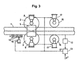
- a profile 1 in a universal roll stand be rolled.
- the profile 1 is according to Figure 1 as a symmetrical Double-T profile. But it could, for example also as a rail profile, as an X-beam, as a T-beam or be designed as a different profile.
- the universal roll stand has horizontal rolls 2, 3 and vertical rolls 4, 5 on.
- the vertical rollers 4, 5 have vertical Roll centers 6, 7 on.
- the vertical rollers 4, 5 are there built into the universal mill stand so that its vertical Roll centers 6, 7 are arranged at the same height.
- Actuators 8 to 11 are assigned to rollers 4 to 7.
- the Actuators 8 to 11 are hydraulic cylinder units educated.
- rollers 4 to 7 can be roughly preset via further actuators, not shown, in particular electromechanical actuators. It is crucial, however, that the setting of roll gaps takes place both in the no-load state and under load via the hydraulic cylinder units 8 to 11. If appropriate horizontal or Vertical target roll gaps h * , v1 * , v2 * are thus the horizontal rolls 2, 3 against the horizontal target roll gap h * against each other on a horizontal actual roll gap h. The vertical rolls 4, 5 are set against the horizontal rolls 2, 3 on vertical actual roll gaps v1, v2. The adjustment or adjustment of the rollers 2 to 5 always takes place via the hydraulic cylinder units 8 to 11.
- the horizontal desired nip h * is predefined for the horizontal rolls 2, 3 or their hydraulic cylinder units 8, 9 at a start time t0.
- the horizontal rollers 2, 3 and their actuators 8, 9 are also given an additional setpoint o * at this time.
- the horizontal rollers 2, 3 are adjusted to actual positions x1, x2 with respect to the vertical roller centers 6, 7.
- the zero line is defined by the vertical roller centers 6, 7, which coincide.
- the horizontal rolls 2, 3 are adjusted symmetrically with respect to the vertical roll centers 6, 7 due to the horizontal desired nip h * .
- the horizontal rollers 2, 3 are vertically adjusted in the same direction. This results in a vertical displacement of the horizontal rolls 2, 3 with respect to the vertical roll centers 6, 7 while at the same time maintaining the horizontal actual roll gap h formed by the horizontal rolls 2, 3.
- the nominal roll gaps h * , v1 * , v2 * and the additional nominal value o * are kept constant while the profile 1 is being rolled.
- a new additional setpoint o * can be specified at a change time t3 that lies between the run-in time t1 and the run-out time t2. It is also possible to change the nominal roll gaps h * , v1 * , v2 * .
- a horizontal measuring device 12 is arranged downstream of the horizontal and vertical rollers 2-5.
- the rolled profile 1 can be detected by means of the profile measuring device 12.
- the profile measuring device 12 is connected to a profile controller 13 for control purposes.
- a target profile P * can be fed to the profile controller 13.
- the profile controller 13 compares the rolled profile 1 with the target profile P * and uses the comparison to determine the additional target value o *.
- the profile controller 13 is connected to the actuators 8, 9 for the horizontal rolls 2, 3 in terms of control technology. He can therefore directly transmit the additional setpoint o * to the actuators 8, 9.
- the transmission can be made either continuously or discretely (ie between two profiles 1 to be rolled).
- the horizontal and vertical rollers 2-5 are preceded by a roller table 14 for the profile 1. Furthermore, the horizontal and vertical rollers 2 - 5 are followed by a flange compression stand 15 for the profile 1.
- the roller table 14 and the flange compression stand 15 each form a component 14, 15 upstream or downstream of the universal rolling stand.
- the components 14, 15 are vertically adjustable via actuators 16, 17.
- the actuators 16, 17 can again be designed as hydraulic cylinder units.
- the components 14, 15 and their actuators 16, 17 are also supplied with the additional setpoint o * .
- the components 14, 15 can thus also be adjusted vertically on the basis of the additional setpoint o * .
- the vertical adjustment of the components 14, 15 can act in the same or opposite direction and can be as large as or smaller than the additional setpoint o * .
- the roller table 14 can be adjusted in the same direction by the same amount as the horizontal rollers 2, 3, and the flange compression stand 15 in the opposite direction by a part of the additional setpoint o * .
Landscapes
- Engineering & Computer Science (AREA)
- Mechanical Engineering (AREA)
- Metal Rolling (AREA)
- Control Of Metal Rolling (AREA)
- Reduction Rolling/Reduction Stand/Operation Of Reduction Machine (AREA)
Applications Claiming Priority (2)
| Application Number | Priority Date | Filing Date | Title |
|---|---|---|---|
| DE19964040 | 1999-12-30 | ||
| DE19964040A DE19964040A1 (de) | 1999-12-30 | 1999-12-30 | Walzverfahren für ein Profil, insbesondere ein Flanschprofil, und hiermit korrespondierendes Universalwalzgerüst |
Publications (2)
| Publication Number | Publication Date |
|---|---|
| EP1112783A2 true EP1112783A2 (fr) | 2001-07-04 |
| EP1112783A3 EP1112783A3 (fr) | 2004-01-02 |
Family
ID=7935168
Family Applications (1)
| Application Number | Title | Priority Date | Filing Date |
|---|---|---|---|
| EP00126742A Withdrawn EP1112783A3 (fr) | 1999-12-30 | 2000-12-06 | Procédé de laminage d'un profilé, en particulier d'un profilé à ailes, et cage de laminoir universel correspondante |
Country Status (5)
| Country | Link |
|---|---|
| US (1) | US20010023605A1 (fr) |
| EP (1) | EP1112783A3 (fr) |
| JP (1) | JP2001205306A (fr) |
| KR (1) | KR20010062796A (fr) |
| DE (1) | DE19964040A1 (fr) |
Cited By (2)
| Publication number | Priority date | Publication date | Assignee | Title |
|---|---|---|---|---|
| CN110153200A (zh) * | 2019-05-06 | 2019-08-23 | 邯郸钢铁集团有限责任公司 | 一种万能轧机水平轧制中心线的标定方法 |
| CN113857237A (zh) * | 2021-07-29 | 2021-12-31 | 北京弥天科技有限公司 | 一种h型钢多级轧制装置 |
Families Citing this family (3)
| Publication number | Priority date | Publication date | Assignee | Title |
|---|---|---|---|---|
| DE10300785B4 (de) | 2003-01-11 | 2019-10-10 | Sms Group Gmbh | Hydraulischer Anstellzylinder zur Walzspalteinstellung |
| CN100566926C (zh) * | 2006-10-16 | 2009-12-09 | 李向辉 | 活塞环行业用i型整体油环线材的加工方法及设备 |
| CN102009065B (zh) * | 2010-12-15 | 2012-07-18 | 山东钢铁股份有限公司 | 轧制不对称横截面金属型材的方法及轧制装置 |
Citations (4)
| Publication number | Priority date | Publication date | Assignee | Title |
|---|---|---|---|---|
| JPS60133908A (ja) * | 1983-12-20 | 1985-07-17 | Nippon Steel Corp | 形鋼の自動板厚制御方法 |
| US4586356A (en) * | 1984-07-02 | 1986-05-06 | Institut De Recherches De La Siderurgie Francaise (Irsid) | Process and apparatus for preventing dissymmetry in rolled beams |
| JPH09271802A (ja) * | 1996-04-02 | 1997-10-21 | Nippon Steel Corp | 形鋼圧延方法及びその装置 |
| JPH10296311A (ja) * | 1997-05-01 | 1998-11-10 | Sumitomo Metal Ind Ltd | H形鋼の厚み制御方法 |
-
1999
- 1999-12-30 DE DE19964040A patent/DE19964040A1/de not_active Withdrawn
-
2000
- 2000-12-06 EP EP00126742A patent/EP1112783A3/fr not_active Withdrawn
- 2000-12-15 US US09/738,867 patent/US20010023605A1/en not_active Abandoned
- 2000-12-25 JP JP2000392225A patent/JP2001205306A/ja not_active Withdrawn
- 2000-12-28 KR KR1020000083519A patent/KR20010062796A/ko not_active Application Discontinuation
Patent Citations (4)
| Publication number | Priority date | Publication date | Assignee | Title |
|---|---|---|---|---|
| JPS60133908A (ja) * | 1983-12-20 | 1985-07-17 | Nippon Steel Corp | 形鋼の自動板厚制御方法 |
| US4586356A (en) * | 1984-07-02 | 1986-05-06 | Institut De Recherches De La Siderurgie Francaise (Irsid) | Process and apparatus for preventing dissymmetry in rolled beams |
| JPH09271802A (ja) * | 1996-04-02 | 1997-10-21 | Nippon Steel Corp | 形鋼圧延方法及びその装置 |
| JPH10296311A (ja) * | 1997-05-01 | 1998-11-10 | Sumitomo Metal Ind Ltd | H形鋼の厚み制御方法 |
Non-Patent Citations (3)
| Title |
|---|
| PATENT ABSTRACTS OF JAPAN vol. 009, no. 297 (M-432), 25. November 1985 (1985-11-25) -& JP 60 133908 A (SHIN NIPPON SEITETSU KK), 17. Juli 1985 (1985-07-17) * |
| PATENT ABSTRACTS OF JAPAN vol. 1998, no. 02, 30. Januar 1998 (1998-01-30) -& JP 09 271802 A (NIPPON STEEL CORP), 21. Oktober 1997 (1997-10-21) * |
| PATENT ABSTRACTS OF JAPAN vol. 1999, no. 02, 26. Februar 1999 (1999-02-26) -& JP 10 296311 A (SUMITOMO METAL IND LTD), 10. November 1998 (1998-11-10) * |
Cited By (4)
| Publication number | Priority date | Publication date | Assignee | Title |
|---|---|---|---|---|
| CN110153200A (zh) * | 2019-05-06 | 2019-08-23 | 邯郸钢铁集团有限责任公司 | 一种万能轧机水平轧制中心线的标定方法 |
| CN110153200B (zh) * | 2019-05-06 | 2021-02-26 | 邯郸钢铁集团有限责任公司 | 一种万能轧机水平轧制中心线的标定方法 |
| CN113857237A (zh) * | 2021-07-29 | 2021-12-31 | 北京弥天科技有限公司 | 一种h型钢多级轧制装置 |
| CN113857237B (zh) * | 2021-07-29 | 2024-04-16 | 北京弥天科技有限公司 | 一种h型钢多级轧制装置 |
Also Published As
| Publication number | Publication date |
|---|---|
| US20010023605A1 (en) | 2001-09-27 |
| KR20010062796A (ko) | 2001-07-07 |
| JP2001205306A (ja) | 2001-07-31 |
| EP1112783A3 (fr) | 2004-01-02 |
| DE19964040A1 (de) | 2001-07-05 |
Similar Documents
| Publication | Publication Date | Title |
|---|---|---|
| DE102005021769A1 (de) | Verfahren und Vorrichtung zur gezielten Beeinflussung der Vorbandgeometrie in einem Vorgerüst | |
| DE112005002080T5 (de) | Verfahren zum Design von Walzenprofil und Walze zur Unterdrückung nichtquadratischer Wellen | |
| EP0399296B1 (fr) | Justification automatique d'un laminoir universel après le changement des cylindres pour les profils neufs | |
| DE2543738A1 (de) | Verfahren und kalander zur herstellung von folien | |
| EP1456421B1 (fr) | Procede et dispositif pour dresser et refroidir de maniere regulee un feuillard metallique large, notamment un feuillard d'acier ou une tole, sortant d'un laminoir a chaud pour feuillards | |
| EP1761345A1 (fr) | Dispositif pour solliciter les surfaces de guidage de pieces incorporees de palier guidees dans des ouvertures de montants de cages de laminoirs | |
| DE102006024101A1 (de) | Walzgerüst und Verfahren zum Walzen eines Walzbandes | |
| EP0972581B1 (fr) | Procédé de laminage pour produits en forme de barres, notamment d'acier en barres ou de fils | |
| DE19618712B4 (de) | Regelverfahren für ein Walzgerüst zum Walzen eines Bandes | |
| DE3422762A1 (de) | Verfahren zur reibungskompensation in einem walzwerk | |
| DE2437545B2 (de) | Verfahren zum Walzen von Metallstäben | |
| EP0329999B1 (fr) | Procédé et dispositif de régulation d'épaisseur d'âme et d'aile dans des cages de laminoirs universels | |
| EP1112783A2 (fr) | Procédé de laminage d'un profilé, en particulier d'un profilé à ailes, et cage de laminoir universel correspondante | |
| DE102011110938A1 (de) | Verfahren und Vorrichtung zum Herstellen kalt gepilgerter Rohre | |
| EP2604351A1 (fr) | Laminage des profiles | |
| DE3401894A1 (de) | Verfahren zum herstellen von walzband mit hoher bandprofil- und bandplanheitsguete | |
| EP0757599B1 (fr) | Procede et dispositif pour laminer des poutrelles a partir d'ebauches de profiles | |
| EP0065533B1 (fr) | Procede pour laminer un profile en acier en forme d'u ou analogue et train de poutrelles universel pour la mise en oeuvre du procede | |
| EP1018376A2 (fr) | Train de laminage pour laminer des produits en forme de barres, p.e. d'acier en barres ou de fils | |
| DE3245031A1 (de) | Walzgeruest | |
| EP4100178B1 (fr) | Procédé d'étalonnage automatique de rouleaux verticaux d'une cage de laminoir verticale et système d'étalonnage pour mettre en oeuvre ce procédé | |
| DE1527612B2 (de) | Einrichtung zum regeln der dicke und querschnittsform bzw. ebenheit von blechen und baendern in walzwerken | |
| WO2000029139A1 (fr) | Cage de laminoir dote de cylindres d'appui et de travail | |
| WO2022243425A1 (fr) | Procédé de fonctionnement d'une cage de laminage | |
| WO2017178145A1 (fr) | Régulation de tension de bande robuste |
Legal Events
| Date | Code | Title | Description |
|---|---|---|---|
| PUAI | Public reference made under article 153(3) epc to a published international application that has entered the european phase |
Free format text: ORIGINAL CODE: 0009012 |
|
| 17P | Request for examination filed |
Effective date: 20001215 |
|
| AK | Designated contracting states |
Kind code of ref document: A2 Designated state(s): AT BE CH CY DE DK ES FI FR GB GR IE IT LI LU MC NL PT SE TR |
|
| AX | Request for extension of the european patent |
Free format text: AL;LT;LV;MK;RO;SI |
|
| PUAL | Search report despatched |
Free format text: ORIGINAL CODE: 0009013 |
|
| PUAF | Information related to the publication of a search report (a3 document) modified or deleted |
Free format text: ORIGINAL CODE: 0009199SEPU |
|
| STAA | Information on the status of an ep patent application or granted ep patent |
Free format text: STATUS: THE APPLICATION IS DEEMED TO BE WITHDRAWN |
|
| AK | Designated contracting states |
Kind code of ref document: A3 Designated state(s): AT BE CH CY DE DK ES FI FR GB GR IE IT LI LU MC NL PT SE TR |
|
| AX | Request for extension of the european patent |
Extension state: AL LT LV MK RO SI |
|
| D17D | Deferred search report published (deleted) | ||
| 18D | Application deemed to be withdrawn |
Effective date: 20030701 |