EP1111747A2 - Geräteschrank - Google Patents
Geräteschrank Download PDFInfo
- Publication number
- EP1111747A2 EP1111747A2 EP00127545A EP00127545A EP1111747A2 EP 1111747 A2 EP1111747 A2 EP 1111747A2 EP 00127545 A EP00127545 A EP 00127545A EP 00127545 A EP00127545 A EP 00127545A EP 1111747 A2 EP1111747 A2 EP 1111747A2
- Authority
- EP
- European Patent Office
- Prior art keywords
- area
- cable
- cabinet according
- installation space
- devices
- Prior art date
- Legal status (The legal status is an assumption and is not a legal conclusion. Google has not performed a legal analysis and makes no representation as to the accuracy of the status listed.)
- Granted
Links
- 238000009434 installation Methods 0.000 claims abstract description 45
- 239000000969 carrier Substances 0.000 claims abstract description 8
- 238000005452 bending Methods 0.000 claims description 12
- 239000002184 metal Substances 0.000 claims description 4
- 239000000463 material Substances 0.000 claims description 3
- 210000002414 leg Anatomy 0.000 description 14
- 239000000835 fiber Substances 0.000 description 5
- 238000004804 winding Methods 0.000 description 3
- 230000000295 complement effect Effects 0.000 description 2
- 238000012423 maintenance Methods 0.000 description 2
- 238000009423 ventilation Methods 0.000 description 2
- 230000004308 accommodation Effects 0.000 description 1
- 206010000496 acne Diseases 0.000 description 1
- 239000003795 chemical substances by application Substances 0.000 description 1
- 238000005253 cladding Methods 0.000 description 1
- 238000003780 insertion Methods 0.000 description 1
- 230000037431 insertion Effects 0.000 description 1
- 238000004519 manufacturing process Methods 0.000 description 1
- 238000000034 method Methods 0.000 description 1
- 210000000689 upper leg Anatomy 0.000 description 1
- 238000011144 upstream manufacturing Methods 0.000 description 1
Images



Classifications
-
- H—ELECTRICITY
- H02—GENERATION; CONVERSION OR DISTRIBUTION OF ELECTRIC POWER
- H02B—BOARDS, SUBSTATIONS OR SWITCHING ARRANGEMENTS FOR THE SUPPLY OR DISTRIBUTION OF ELECTRIC POWER
- H02B1/00—Frameworks, boards, panels, desks, casings; Details of substations or switching arrangements
- H02B1/20—Bus-bar or other wiring layouts, e.g. in cubicles, in switchyards
- H02B1/202—Cable lay-outs
-
- H—ELECTRICITY
- H02—GENERATION; CONVERSION OR DISTRIBUTION OF ELECTRIC POWER
- H02B—BOARDS, SUBSTATIONS OR SWITCHING ARRANGEMENTS FOR THE SUPPLY OR DISTRIBUTION OF ELECTRIC POWER
- H02B1/00—Frameworks, boards, panels, desks, casings; Details of substations or switching arrangements
- H02B1/26—Casings; Parts thereof or accessories therefor
- H02B1/30—Cabinet-type casings; Parts thereof or accessories therefor
- H02B1/32—Mounting of devices therein
- H02B1/34—Racks
- H02B1/36—Racks with withdrawable units
-
- H—ELECTRICITY
- H05—ELECTRIC TECHNIQUES NOT OTHERWISE PROVIDED FOR
- H05K—PRINTED CIRCUITS; CASINGS OR CONSTRUCTIONAL DETAILS OF ELECTRIC APPARATUS; MANUFACTURE OF ASSEMBLAGES OF ELECTRICAL COMPONENTS
- H05K7/00—Constructional details common to different types of electric apparatus
- H05K7/14—Mounting supporting structure in casing or on frame or rack
- H05K7/1485—Servers; Data center rooms, e.g. 19-inch computer racks
- H05K7/1488—Cabinets therefor, e.g. chassis or racks or mechanical interfaces between blades and support structures
- H05K7/1491—Cabinets therefor, e.g. chassis or racks or mechanical interfaces between blades and support structures having cable management arrangements
Definitions
- the invention relates to a cabinet according to the preamble of claim 1 and a device for cable management in a cabinet according to the preamble of Claim 25.
- the invention is particularly intended for server cabinets, where servers are stacked and extendable in one Installation space are arranged.
- the wiring is done of the devices on the back, and also devices for feeding the connecting cables of the devices are usually in a rear area arranged behind the installation space.
- the horizontal cable routing in the rear area of the Equipment cabinets can hinder accessibility of the devices in terms of cabling and maintenance options the server bays.
- A1 is a control cabinet with a door known, on the hinge wiring is performed.
- a wire winding device is used to produce the wiring used with which the wire to be laid is contact-proof is wrapped around retaining pins.
- DE 295 15 297 U1 describes a device for telescopic suction pipes from vacuum cleaners to electrical connections described of combinable additional devices via cable connections.
- the telescopic suction tube is with a magazine tube connectable and the cable connection in the magazine tube is pulley-like arranged and over a loose, spring-loaded Roll as a loop, the role in an end region of the magazine tube via a pull-out End is led.
- a cupboard or scaffold for inserting racks electrical systems is described in DE 32 43 063 C2.
- the individual Insert levels of separately assigned support elements are arranged.
- the carrier elements be arranged asymmetrically and instruct an end region on wall elements, which a cable and limit the connection space.
- the cable and connection room is used for vertical cable routing.
- a horizontal cable routing takes place behind the insertion area, from which a limited Accessibility and a relatively small cabinet depth result.
- the invention has for its object to provide a cabinet, which is inexpensive to manufacture with an increased installation space and enables optimized cable routing.
- a particularly advantageous device for cable routing in an equipment cabinet according to the invention is to be created.
- a basic idea of the invention can be seen in one by an asymmetrical arrangement of the installation space formed, lateral free space, which right or left can be arranged next to the installation space for vertical and horizontal cable routing and cable carrier to be provided, which correspond to one another in the installation space arranged devices in the lateral free space horizontally are arranged and the cable routing to the back guarantee the devices in an optimized arrangement.
- Equipment cabinet on components of the previously known equipment cabinets i.e. on a base, cladding parts attached to it and vertical profiles that cover the installation space limit, fall back, preferably the width the equipment cabinet varies and for example with one 19 "rack can be enlarged from 600 mm to 700 mm.
- the asymmetrical arrangement of the installation space can be in one achieved particularly simple, inexpensive way that three of the vertical profiles of the installation space, i.e. a profile on the front and the two on the back Profiles, offset towards the base frame and e.g. directly or indirectly attached to the base frame and the second front profile to form the side Free space inwards towards the installation space to be ordered.
- An advantage of lateral horizontal and / or vertical Cable routing or cable supply for 19 "or 24" bays is that an optimal feeding out one cable trunk possible and in particular no additional one Height unit for a cable floor is required. It will a space-saving, tidy and service-friendly solution for many applications in 19 "or 24" equipment cabinet guaranteed, this also when pulling out the slots is secured.
- the equipment cabinet can for example a depth of 900 mm and a height of 1970 mm have.
- the left or right next to the installation space, lateral space is available for the cable routing or Cable management trained.
- an additional, especially front area of the lateral space for installing devices with the corresponding Dimensions, in particular a suitable depth can be used. Behind this additional installation space become devices for horizontal cable routing and advantageously also for vertical cable routing arranged over, for example, a cable trunk.
- Both aforementioned cabinet dimensions can be in the additional installation space e.g. three slots of each two height units, but one on top of the other be arranged and have a relatively shallow depth, be accommodated.
- the side Free space can then be from one rear vertical or 19 "profile up to staggered inside, front vertical profile and a front vertical spar of the equipment cabinet pass.
- the cable carriers are expediently designed as support plates and provided with deflection or guide elements. These are arranged such that a cable deflection approximately in the middle of the travel of the extendable devices without a tensile load and without kinking is guaranteed. By the cable routing or the cable management the cables fixed to about 50% of the travel distance, the free cable length be minimized. In addition to this material and cost Defined bending radii can also be an advantage achieved by arranging guide and deflection elements become. Joints and can be used as guide and deflection elements Deflection pulleys as well as drag or cable routing chains or also flexible pipes can be arranged.
- pivoting support arms can be used for horizontal cable routing in the side clearance be arranged.
- the support arms are convenient horizontally aligned, adjustable about a vertical swivel axis and have a length that is about half The path of the extendable devices corresponds.
- the support arms can also be designed as a cable guide chain be made up of a variety of against each other pivotable chain links.
- the cable routing chain which can also be called a drag chain, can on a vertical pivot axis on the support plate or another part of the equipment cabinet and with the other Be attached to the 19 "or 24" slot at the end.
- the connecting cables performed in a defined bending radius, so that orderly and safe cabling is guaranteed. There is free access to the components of the slot, for example for the power supply or the boards, possible.
- fiber optic cables are also defined turned and led. There is a kink in the fiber optic cables locked out.
- Support arm e.g. a cable chain or one Cable bridge with a movable head section, swiveling to fix.
- the pivot axes of the alternatively trained Support arms on the cable carrier are useful in the area of half the travel distance of the extendable devices.
- a cable bridge with a movable head part is not only for a side cable management, but for all horizontal Cable routing advantageous.
- the cable bridge is in principle U-shaped or C-shaped, so that the Cables can be inserted from above.
- the cable bridge has a rigid area and a movable area on which consists of defined link elements consists.
- the rigid area can be made of metal and the link elements made of a plastic his.
- the movable area is at one end of the rigid area in particular arranged pivotably and with his attach the free end to the slot. Basically can the movable area can also be arranged on the rack side.
- Another alternative is to move Swiveling area between two rigid areas to attach or using a rigid area two movable areas, which at both ends of the rigid area are arranged to provide.
- the link elements of the movable Form area so that a swing out only in one direction, i.e. to the right or left, possible is. It is also advisable to set a maximum bending radius, especially for fiber optic cables, through the link elements to specify.
- the bending radius and / or the swing out in one direction can in the cable bridge according to the invention by a polygonal, e.g. octagonal base of the Link elements and trapezoidal vertical legs two opposite edges can be specified. Due to a different edge length of the base can the opposite trapezoidal Legs of different widths are formed, whereby a maximum bending radius and / or pivoting into one or both directions can be specified.
- the height of the trapezoidal Leg corresponds to the leg height of the fixed part.
- the devices or servers are known per se Pull-out elements, e.g. Telescopic rails, extendable or can be arranged like a slide-in.
- the telescopic rails are on the outside towards the base frame or offset vertically towards the installation space.
- 19 “profiles attached, with the back areas the telescopic rails adjoining the side clearance on rear holding devices, e.g. U or L shaped Angles can be attached.
- the back Holding devices can expediently on the base frame be attached and at the same time to attach the cable carrier, especially the support plates.
- a front area of the side clearance as additional installation space for plug-ins is used advantageous to arrange a front vertical support.
- the front vertical support can at least accommodate a slide-in rail of the additional installation space and at the same time for fastening the horizontal cable carrier serve.
- the rear holding devices for Bridging the distance between the base frame or the rear vertical spar and the telescopic rails of the pull-out devices or servers as U- or L-shaped angle profiles are formed, there is the particularly advantageous Possibility of using the angle profiles for vertical cable routing and / or for fastening cable holders use.
- a device cabinet door can be or be arranged to the right.
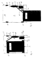
- a device cabinet 2 is a server cabinet with an installation space 3 for one above the other Server as devices 4 in a highly schematic representation shown.
- the same features are used in all the figures provided identical reference numerals.
- the installation space 3 is asymmetrical, in this embodiment offset to the left, arranged, whereby to the right
- a lateral free space 5 is formed becomes.
- the lateral free space 5 is in a front area formed as an additional installation space 12, which in this example for the arrangement of three 19 "bays 13 trained, which are arranged upright (see also Fig. 3).
- Behind the inserts 13 are in a central area 15 cable carrier 6 for horizontal cable routing (not shown) complementary to those arranged one above the other Devices 4 arranged.
- a rear area 14 is behind the installation space 3 essentially kept clear of the horizontal cable routing and serves the wiring of the devices 4 with each other and the introduction of the cables (not shown) from the lateral clearance 5. From FIGS. 1 and 2 it can be seen that the rear area 14 basically for deeper Devices 4, for example servers, can be used.
- the asymmetrical arrangement of the installation space 3 for the one above the other arranged devices 4 is achieved in that rear vertical profiles 22, 23 and a front Vertical profile 21 offset towards the base frame and on the base frame, for example on an upper one and lower frame (not shown), the equipment cabinet 2 are attached.
- a front vertical profile 24 is to form the lateral clearance 5 inwards Offset towards the installation space.
- multi-function struts (not shown) can be provided become. Fastening and arrangement of the cable carrier 6 and of pull-out elements for the devices 4 and inserts 13 in connection with FIG. 5 and in the other figures explained.
- the device cabinet 2 has a width of 700 mm in this embodiment and a depth of 900 mm and a height of 1800 mm (38 Height units).
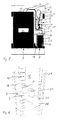
- the 19 "installation space 3 are according to the Figures 3 and 4 six servers or devices 4 and in an additional Installation space 12, which in a front Area of the lateral clearance 5 is formed, three vertically arranged 19 "slots 13 of two each Height units arranged.
- FIG. 4 2 The rear view of the equipment cabinet shown in FIG. 4 2 without rear wall illustrates the vertical guidance the cable 10 and arranged approximately at the level of the devices 4 Cable carrier 6 for the horizontal routing of the cables 10 in the side clearance 5.
- a Equipment cabinet 2 is an arrangement for horizontal Cable routing also in a central area 15 of the lateral clearance 5.
- Cable carrier 6 support plates 7 arranged, which with a Hole pattern 11 are provided.
- the hole pattern 11 is used for Inclusion of guide and / or deflection elements 9, which thereby adjusted and the travel of the extendable devices 4 can be adjusted.
- Cables 10 are in intervals attached cable holders 30 vertically and in the area of the support plates 7 guided horizontally, on the guide and deflection elements 9 deflected and on a support arm 8, which as a 90 ° bent tow or Cable guide chain 31 (see also Fig. 9) is formed arranged to a rear area 14 and to the devices 4, guided safely and without kinks.
- the support plate 7 is on a front vertical support 16 and indirectly via rear holding devices 17 on rear vertical profile 23 attached.
- the back Holding devices 17 are in this embodiment U-shaped angles arranged, at the same time cable holder 30 fixed for the vertical guidance of the cable 10 are.
- the rear holding devices 17 are with a inner thigh on the outwardly displaced, rear Vertical profile 23 attached and serve with a inside, parallel legs for fastening pull-out elements 19, in particular of telescopic rails, (see Fig. 7) for the devices 4.
- the slots 13 in the front Installation space 12 are held on slide rails 18, which is attached to the front vertical support 16 can be. Alternatively, the inserts 13 can also be used a front attachment can be held.
- a vertical support 16 is shown.
- support plates 7 For detachable and tool-free mounting of support plates 7 as Cable carriers 6 have slots 32 formed in a grid-like manner, in which the support plates 7 with a complementary Engage the fastener (not shown) and preferably click into place.
- the support plate shown in Fig. 6 7 is a folded sheet with at least a mounting flange 33 for screw mounting on the vertical profile with a hole pattern 34 on the back 23 and with a turn 35 on which the Cable (not shown) led in the vertical direction are provided.
- For redirecting the cables on the support plate 7 are approximately semicircular guide and deflection elements 9 on fasteners of the support plate, not shown 7 attached.
- the pimple or rod-like, for example Fastening elements are arranged such that the Deflection elements 9, which e.g. made of a plastic material are made, can be attached optionally and adjustable can.
- the lateral clearance 5 was not with one additional front installation space, but almost completely to horizontal cable routing with the help a cable carrier 6 in the form of a support plate 7.
- the support plate 7 is approximately Z-shaped Sheet metal and with three guide rollers 9 with several roller segments provided for cables 10 run one above the other.
- the horizontal one Cable carrier 6 extends from the inward, front vertical profile 24 and a front Vertical spar 25 up to the rear, offset to the outside Vertical profile 23.
- a server 4 is pulled out Position shown.
- pull-out elements 19 are on the right, as usual, telescopic rails on the vertical profiles 21, 23 and left attached to the front vertical profile 24.
- the section of an equipment cabinet 2 shown in FIG. 8 also shows a device 4 pulled out to the front and Wiring 37 on the back.
- two support plates 7 are arranged one above the other.
- the lower support plate 7 has three deflection or Guide rollers 9 for cable 10, which in the area of Back of the device 4 another strain relief (not shown) exhibit.
- the upper support plate 7 is also provided with pulleys 9 and also has a pivotable Support arm 8 on.
- the pivoting support arm 8 is a U-shaped rail with an open top vertical pivot axis 38 is formed. The length of the support arm 8 and the arrangement of the vertical pivot axis 38 are adapted to the travel path of the pull-out device 4, the length is approximately half of the travel.
- FIG. 9 shows a section of an appliance cabinet according to the invention 2 with a device insert 4, in this case a server, in the extended position. From that for that Server 4 provided side cable management are in Fig. 9, a support plate 7, which on a front Vertical support 16 and on a back, to the outside offset vertical profile 23 is attached, and a pull-out element 19 shown, which on an L-shaped rear holding device 17 and not at one front vertical profile 21 shown attached is.
- Fig. 9 illustrates that access to the power supply and to all plugs is free and also the air flow not hindered by cables 10 in the equipment cabinet becomes. A defined radius for those routed to server 4 Cable 10, especially for fiber optic cables, is through a Tow or Cable guide chain 31 guaranteed.
- This cable routing chain 31 has a corresponding number of Chain links that are pivotally connected to each other are that a predefinable bending radius is guaranteed is.
- the cable guide chain 31 is on the rack side via a vertical axis 38 pivotable on the support plate 7 and attached to the server 4 via a bracket 39.
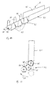
- the support arm 8 is as a cable bridge 40 with a rigid area 41 and a movable area 42.
- the rigid one Area 41 is made of metal
- the movable area 42 comprises link elements 43, which are made of plastic are.
- the link elements 43 are designed such that a definable swiveling to one side and / or a predeterminable radius can be reached.
- Both the rigid Area 41 as well as the movable area 42 with those shown three link elements 43 is U-shaped.
- the link elements 43 each have a base area 44, which is polygonal, octagonal in this embodiment, is formed, and two parallel legs 45, 46 on, which are trapezoidal, but different Have width.
- the height of the trapezoidal Legs 45, 46 correspond to the height of the legs of the fixed part 41. Cables (not shown) can be inserted from above and guided without kinks, since the predeterminable Width of the trapezoidal legs 45, 46 only a certain one Allow bending radius.
- the cable bridge 40 shown in FIGS. 10 and 11 is a swiveling out to the left according to arrow 47 in FIG. 11 intended.
- the wider legs 45 prevent one Right swing of the movable part 42 around the vertical Pivot axes 48, which are arranged in the area of the base surfaces 44 are. Due to the width of the narrower legs 46, which are arranged on the left in this exemplary embodiment, the maximum turning radius can also be limited to the left be, so that a kink-free cable routing, in particular of fiber optic cables.
- Others can Delimiting elements are provided and e.g. on the base areas 44 of the link elements 43 may be arranged.
- the cable bridge according to the invention with at least one movable Part is extremely inexpensive through one Stamping and bending process can be produced and is simple and quick to assemble.
Landscapes
- Engineering & Computer Science (AREA)
- Power Engineering (AREA)
- Computer Hardware Design (AREA)
- General Engineering & Computer Science (AREA)
- Microelectronics & Electronic Packaging (AREA)
- Insertion, Bundling And Securing Of Wires For Electric Apparatuses (AREA)
- Structure Of Telephone Exchanges (AREA)
- Steering-Linkage Mechanisms And Four-Wheel Steering (AREA)
Abstract
Description
- Fig. 1
- einen Querschnitt eines erfindungsgemäßen Geräteschrankes mit einem Gerät in eingeschobener Betriebsstellung;
- Fig. 2
- einen Querschnitt des erfindungsgemäßen Geräteschrankes nach Fig. 1, jedoch mit herausgezogenem Gerät;
- Fig. 3
- eine frontseitige Ansicht des Geräteschrankes nach Fig. 1, jedoch ohne Fronttür;
- Fig. 4
- eine rückseitige Ansicht des Geräteschrankes nach Fig. 1 und 3, jedoch ohne Rückwand;
- Fig. 5
- einen Querschnitt eines alternativ ausgebildeten erfindungsgemäßen Geräteschrankes;
- Fig. 6
- eine ausschnittsweise perspektivische Darstellung eines erfindungsgemäßen Geräteschrankes im Bereich der seitlichen Kabelführung;
- Fig. 7
- eine ausschnittsweise perspektivische Darstellung eines erfindungsgemäßen Geräteschrankes im Bereich einer unteren seitlichen Kabelführung mit herausgezogenem Gerät;
- Fig. 8
- eine ausschnittsweise perspektivische Darstellung eines erfindungsgemäßen Geräteschrankes im Bereich zweier seitlicher Kabelführungen mit herausgezogenem Gerät;
- Fig. 9
- eine ausschnittsweise perspektivische Darstellung einer erfindungsgemäßen Kabelführung mit einer Kabelführungskette;
- Fig. 10
- eine perspektivische Darstellung einer Kabelbrücke mit beweglichem Teil und
- Fig. 11
- eine Draufsicht auf eine Kabelbrücke nach Fig. 10.
Claims (34)
- Geräteschrank
mit einem Einbauraum (3) für einschubartig angeordnete elektrische und elektronische Geräte (4), insbesondere Server, und mit einem Bereich (14) zur Verkabelung der Geräte (4), wobei der Einbauraum (3) unter Ausbildung eines seitlichen Freiraums (5) asymmetrisch angeordnet und der seitliche Freiraum (5) zur Kabelführung ausgebildet ist,
dadurch gekennzeichnet,dass zur horizontalen Führung von Kabeln (10) zu dem Bereich (14) und zu den Geräten (4) Kabelträger (6) in dem seitlichen Freiraum (5) vorgesehen sind, unddass die Kabelträger (6) entsprechend den übereinander angeordneten Geräten (4) horizontal angeordnet sind. - Geräteschrank nach Anspruch 1,
dadurch gekennzeichnet,
dass als Kabelträger (6) Tragplatten (7) in dem seitlichen Freiraum (5) angeordnet sind. - Geräteschrank nach Anspruch 1,
dadurch gekennzeichnet,
dass als Kabelträger (6) Tragarme (8) verschwenkbar in dem seitlichen Freiraum (5) angeordnet sind. - Geräteschrank nach Anspruch 3,
dadurch gekennzeichnet,
dass jeweils ein Tragarm (8) an einer Tragplatte (7) befestigt ist. - Geräteschrank nach Anspruch 3 oder 4,
dadurch gekennzeichnet,
dass die Tragarme (8) eine Länge aufweisen, welche etwa dem halben Verfahrweg der einschubartig angeordneten Geräte (4) entspricht. - Geräteschrank nach einem der Ansprüche 2 bis 5,
dadurch gekennzeichnet,
dass die Tragplatten (7) Führungs- und/oder Umlenkelemente (9) für die Kabel (10) aufweisen. - Geräteschrank nach Anspruch 6,
dadurch gekennzeichnet,
dass als Führungs- und Umlenkelemente (9) Gelenke und Umlenkrollen angeordnet sind. - Geräteschrank nach einem der Ansprüche 2 bis 7,
dadurch gekennzeichnet,
dass die Tragplatten (7) mit einem Lochraster (11) zur verstellbaren Aufnahme der Führungs- und Umlenkelemente (9) und/oder der Tragarme (8) versehen sind. - Geräteschrank nach einem der vorhergehenden Ansprüche,
dadurch gekennzeichnet,
dass der seitliche Freiraum (5) in einem frontseitigen Bereich als zusätzlicher Einbauraum (12) für Geräte (13) mit entsprechenden Abmessungen ausgebildet ist. - Geräteschrank nach Anspruch 9,
dadurch gekennzeichnet,
dass bei einer Schrankbreite von 700 mm und einer Schrankhöhe von 48 Höheneinheiten sowie einem Einbauraum (3), welcher dem 19"-System entspricht, der seitlich und frontseitig ausgebildete, zusätzliche Einbauraum (12) zur Aufnahme von drei vertikal angeordneten 19"-Einschüben (13) von jeweils drei Höheneinheiten und entsprechender Tiefe vorgesehen ist. - Geräteschrank nach einem der Ansprüche 2 bis 10,
dadurch gekennzeichnet,
dass die Kabelträger (6) wenigstens in einem Mittenbereich (15) des seitlichen Freiraums (5) angeordnet und an wenigstens einer frontseitigen Vertikalstütze (16) und einem rückseitigen, nach außen in Richtung Grundgestell versetzten Vertikalprofil (23) befestigt sind. - Geräteschrank nach Anspruch 11,
dadurch gekennzeichnet,
dass die frontseitige Vertikalstütze (16) zur Befestigung von Einschubschienen (18), welche in dem zusätzlichen Einbauraum (12) zur Aufnahme der 19"-Einschübe (13) angeordnet sind, ausgebildet ist. - Geräteschrank nach Anspruch 11 oder 12,
dadurch gekennzeichnet,
dass rückseitige Halteeinrichtungen (17) zur Befestigung von Auszugselementen (19) für die Geräte (4) des Einbauraums (3) vorgesehen und an dem rückseitigen, nach außen in Richtung Grundgestell versetzten Vertikalprofil (23) befestigt sind. - Geräteschrank nach Anspruch 13,
dadurch gekennzeichnet,
dass die rückseitigen Halteeinrichtungen (17) als im Querschnitt U- oder L-förmige Winkel ausgebildet sind. - Geräteschrank nach einem der Ansprüche 11 bis 14,
dadurch gekennzeichnet,
dass die frontseitige Vertikalstütze (16) zur lösbaren und/oder werkzeuglosen Aufnahme der Tragplatten (7) ausgebildet ist. - Geräteschrank nach einem der vorhergehenden Ansprüche,
dadurch gekennzeichnet,
dass der seitliche Freiraum (5) zur Kabelführung rechts oder links neben dem Einbauraum (3) angeordnet ist. - Geräteschrank nach einem der vorhergehenden Ansprüche,
dadurch gekennzeichnet,
dass zur asymmetrischen Anordnung des Einbauraums (3) ein frontseitiges Profil (21) und die zwei rückseitigen Profile (22, 23) nach außen in Richtung Grundgestell und das zweite frontseitige Profil (24) zur Ausbildung des seitlichen Freiraums (5) nach innen in Richtung Einbauraum (3) versetzt angeordnet sind. - Geräteschrank nach Anspruch 17,
dadurch gekennzeichnet,
dass das Grundgestell (20) einen rechteckigen oder X-förmigen oberen und unteren Rahmen und frontseitige Vertikalholme (25, 26) und rückseitige Vertikalholme (27, 28) aufweist und dass die nach außen in Richtung Grundgestell versetzten Profile (21, 22, 23) und das nach innen in Richtung Einbauraum versetzte Profil (24) an dem Grundgestell (20) befestigt sind. - Geräteschrank nach einem der Ansprüche 3 bis 18,
dadurch gekennzeichnet,
dass als Tragarm (8) eine Kabelführungskette (31) vorgesehen ist, welche aus Kettengliedern gebildet und schwenkbar im Bereich des Geräteschrankes (2) sowie am ausziehbaren Gerät (4) angeordnet ist. - Geräteschrank nach Anspruch 19,
dadurch gekennzeichnet,
dass die Kabelführungskette (31) mit einem vorgebbaren, definierten Biegeradius ausgebildet ist. - Geräteschrank nach einem der Ansprüche 3 bis 18,
dadurch gekennzeichnet,
dass als Tragarm (8) eine Kabelbrücke (40), welche wenigstens einen starren Bereich (41) und wenigstens einen beweglichen Bereich (42) aufweist, vorgesehen ist, wobei der starre Bereich (41) und der bewegliche Bereich (42) zum Einlegen der Kabel (10) von oben U- oder C-förmig ausgebildet sind. - Geräteschrank nach Anspruch 21,
dadurch gekennzeichnet,
dass der bewegliche Bereich (42) als Kopfteil angeordnet und an einem Ende schwenkbar an dem starren Bereich (41) und am gegenüberliegenden Ende am Gerät (4) fixierbar ist. - Geräteschrank nach Anspruch 21 oder 22,
dadurch gekennzeichnet,
dass der bewegliche Bereich (42) aus Gliederelementen (43) besteht, welche derart ausgebildet sind, dass ein Verschwenken in eine Richtung und/oder mit einem definierten Biegeradius vorgebbar ist. - Geräteschrank nach Anspruch 23,
dadurch gekennzeichnet,
dass die Gliederelemente (43) jeweils eine polygonale, insbesondere achteckige Grundfläche (44) und vertikale Schenkel (45, 46) aufweisen, wobei die vertikalen Schenkel (45, 46) parallel zueinander angeordnet und trapezförmig ausgebildet sind sowie eine unterschiedliche Breite aufweisen. - Einrichtung zur Kabelführung in einem Geräteschrank nach einem der Ansprüche 1 bis 18,
dadurch gekennzeichnet,dass eine Kabelbrücke (40) vorgesehen ist, welche wenigstens einen starren Bereich (41) und wenigstens einen beweglichen Bereich (42) aufweist, unddass der starre Bereich (41) und der bewegliche Bereich (42) zum Einlegen von Kabeln (10) von oben etwa U- oder C-förmig ausgebildet sind. - Einrichtung nach Anspruch 25,
dadurch gekennzeichnet,
dass der bewegliche Bereich (42) Gliederelemente (43) aufweist, welche zueinander und zu dem starren Bereich (41) horizontal verschwenkbar angeordnet sind. - Einrichtung nach Anspruch 25 oder 26,
dadurch gekennzeichnet,
dass der starre Bereich (41) an seinem freien Ende am Geräteschrank (2) und der bewegliche Bereich (42) an seinem freien Ende an einem Gerät (4) fixierbar ist, wobei der starre Bereich (41) über eine vertikale Achse (38) verschwenkbar am Geräteschrank (2), insbesondere an einer Tragplatte (7) einer seitlichen Kabelführung, fixierbar ist. - Einrichtung nach einem der Ansprüche 25 bis 27,
dadurch gekennzeichnet,
dass die Gliederelemente (43) des beweglichen Bereichs (42) derart ausgebildet sind, dass der bewegliche Bereich (42) in eine vorgebbare Richtung und/oder mit einem definierten Biegeradius verschwenkbar ist. - Einrichtung nach Anspruch 28,
dadurch gekennzeichnet,dass die Gliederelemente (43) wie der starre Bereich (41) jeweils eine Grundfläche (44) und zwei vertikale Schenkel (45, 46) aufweisen, wobei die Grundfläche(44) der Gliederelemente (43) polygonal und die Schenkel (45, 46), welche parallel zueinander angeordnet sind, trapezförmig und mit einer unterschiedlichen Breite ausgebildet sind. - Einrichtung nach Anspruch 29,
dadurch gekennzeichnet,
dass die Grundfläche (44) der Gliederelemente (43) achteckig ausgebildet ist und die Schenkel (46) der Gliederelemente (43), in deren Richtung der bewegliche Bereich (42) verstellbar ist, schmaler als die parallelen Schenkel (45) ausgebildet sind. - Einrichtung nach Anspruch 30,
dadurch gekennzeichnet,
dass die Schenkel (45) zur Blockierung einer Abbiegung in eine vorgebbare Richtung eine entsprechende Breite aufweisen. - Einrichtung nach einem der Ansprüche 25 bis 31,
dadurch gekennzeichnet,
dass der starre Bereich (41) aus Metall besteht und die Gliederelemente (43) des beweglichen Bereichs (42) aus einem Kunststoffmaterial gefertigt sind. - Einrichtung nach einem der Ansprüche 25, 28 bis 32,
dadurch gekennzeichnet,
dass die Kabelbrücke (40) einen starren Bereich (41) und zwei bewegliche Bereiche (42) an gegenüberliegenden Endbereichen des starren Bereichs (41) aufweist. - Einrichtung nach einem der Ansprüche 25, 28 bis 32,
dadurch gekennzeichnet,
dass die Kabelbrücke (40) einen beweglichen Bereich (42) und zwei starre Bereiche (41) aufweist, wobei der bewegliche Bereich (42) zwischen den zwei starren Bereichen (41) angeordnet ist.
Applications Claiming Priority (2)
| Application Number | Priority Date | Filing Date | Title |
|---|---|---|---|
| DE19962659 | 1999-12-23 | ||
| DE19962659A DE19962659C2 (de) | 1999-12-23 | 1999-12-23 | Geräteschrank |
Publications (3)
| Publication Number | Publication Date |
|---|---|
| EP1111747A2 true EP1111747A2 (de) | 2001-06-27 |
| EP1111747A3 EP1111747A3 (de) | 2002-04-10 |
| EP1111747B1 EP1111747B1 (de) | 2008-02-13 |
Family
ID=7934265
Family Applications (1)
| Application Number | Title | Priority Date | Filing Date |
|---|---|---|---|
| EP00127545A Expired - Lifetime EP1111747B1 (de) | 1999-12-23 | 2000-12-15 | Geräteschrank |
Country Status (3)
| Country | Link |
|---|---|
| EP (1) | EP1111747B1 (de) |
| AT (1) | ATE386358T1 (de) |
| DE (2) | DE19962659C2 (de) |
Cited By (3)
| Publication number | Priority date | Publication date | Assignee | Title |
|---|---|---|---|---|
| DE10105287C1 (de) * | 2001-02-06 | 2002-08-29 | Fujitsu Siemens Computers Gmbh | Serverrack |
| DE10310283B3 (de) * | 2003-03-07 | 2004-09-16 | Rittal Gmbh & Co. Kg | Umlenkelement zur Kabelführung und Kabelführungsvorrichtung |
| US9173312B1 (en) | 2014-04-30 | 2015-10-27 | Quanta Computer Inc. | Cable storage under a drawer |
Families Citing this family (10)
| Publication number | Priority date | Publication date | Assignee | Title |
|---|---|---|---|---|
| DE10210778B4 (de) * | 2002-03-12 | 2004-06-09 | Rittal Gmbh & Co. Kg | Gehäuse oder Gestell mit einer Kabelführungsvorrichtung |
| DE102006055637B4 (de) * | 2006-11-24 | 2009-02-26 | Fujitsu Siemens Computers Gmbh | Kabelführung |
| DE102008030255B3 (de) * | 2008-06-25 | 2009-08-13 | Fujitsu Siemens Computers Gmbh | Computersystem |
| DE102008060843B3 (de) * | 2008-12-06 | 2010-04-08 | Rittal Gmbh & Co. Kg | Umlenkvorrichtung für Kabel |
| DE202010004681U1 (de) | 2010-04-08 | 2010-07-22 | Knürr AG | Geräteschrank |
| DE102013206663A1 (de) | 2013-04-15 | 2014-10-16 | Krones Ag | Etikettiermaschine mit Schaltschrank |
| US9886068B2 (en) | 2016-03-09 | 2018-02-06 | Microsoft Technology Licensing, Llc | Cable management techniques for computing systems |
| CN113241615B (zh) * | 2021-07-09 | 2021-09-07 | 深圳市壹云智能科技有限公司 | 一种电气控制柜 |
| CN114744507B (zh) * | 2022-04-01 | 2023-12-08 | 江苏益宝电气科技有限公司 | 一种智能型装配式低压gcs开关柜 |
| WO2026162779A1 (en) * | 2025-02-03 | 2026-08-06 | Tiemessen Theodorus Sybout Nicolaas | Compact substation |
Family Cites Families (7)
| Publication number | Priority date | Publication date | Assignee | Title |
|---|---|---|---|---|
| DE3243063A1 (de) * | 1982-11-22 | 1984-05-24 | BBC Aktiengesellschaft Brown, Boveri & Cie., Baden, Aargau | Schrank oder geruest fuer die aufnahme von einschueben elektrischer anlagen |
| DE4125618A1 (de) * | 1991-08-02 | 1993-02-04 | Osteroder Steuerungsbau O S B | Verdrahtung in schaltschraenken und verfahren zur herstellung einer verdrahtung |
| DE29515297U1 (de) * | 1995-09-23 | 1995-11-23 | Stein & Co GmbH, 42553 Velbert | Vorrichtung für Teleskop-Saugrohre von Bodenstaubsaugern |
| GB2321786B (en) * | 1997-01-29 | 1999-09-29 | Beckman Wysse Limited | Equipment rack |
| DE29806284U1 (de) * | 1998-04-06 | 1998-07-23 | Knürr-Mechanik für die Elektronik AG, 81829 München | Einrichtung zur Kabelführung |
| DE29823108U1 (de) * | 1998-12-28 | 1999-07-22 | Rittal-Werk Rudolf Loh GmbH & Co. KG, 35745 Herborn | Aufnahmegehäuse mit einem Rahmengestell |
| DE29909806U1 (de) * | 1999-06-04 | 1999-08-12 | N. Kratz Söhne, 42369 Wuppertal | Aufnahmevorrichtung für elektrische Geräte-Leitungen |
-
1999
- 1999-12-23 DE DE19962659A patent/DE19962659C2/de not_active Expired - Fee Related
-
2000
- 2000-12-15 DE DE50014961T patent/DE50014961D1/de not_active Expired - Lifetime
- 2000-12-15 AT AT00127545T patent/ATE386358T1/de not_active IP Right Cessation
- 2000-12-15 EP EP00127545A patent/EP1111747B1/de not_active Expired - Lifetime
Cited By (3)
| Publication number | Priority date | Publication date | Assignee | Title |
|---|---|---|---|---|
| DE10105287C1 (de) * | 2001-02-06 | 2002-08-29 | Fujitsu Siemens Computers Gmbh | Serverrack |
| DE10310283B3 (de) * | 2003-03-07 | 2004-09-16 | Rittal Gmbh & Co. Kg | Umlenkelement zur Kabelführung und Kabelführungsvorrichtung |
| US9173312B1 (en) | 2014-04-30 | 2015-10-27 | Quanta Computer Inc. | Cable storage under a drawer |
Also Published As
| Publication number | Publication date |
|---|---|
| EP1111747B1 (de) | 2008-02-13 |
| ATE386358T1 (de) | 2008-03-15 |
| DE19962659A1 (de) | 2001-12-13 |
| DE19962659C2 (de) | 2002-03-28 |
| EP1111747A3 (de) | 2002-04-10 |
| DE50014961D1 (de) | 2008-03-27 |
Similar Documents
| Publication | Publication Date | Title |
|---|---|---|
| DE69207745T2 (de) | Stütz- und Führungsgerüst für elektrische und optische Übertragungskabeln | |
| DE4333947A1 (de) | Geräteschrank | |
| EP1111747B1 (de) | Geräteschrank | |
| EP2171817B1 (de) | Vorrichtung zum anordnen und befestigen von elektrischen einheiten insbesondere in einem schaltschrank, sowie ein montagesystem mit einer solchen vorrichtung | |
| EP1336065B1 (de) | Stativkopf, insbesondere für eine medizinische überwachungs- und versorgungseinrichtung, trägerprofil für einen solchen und gerätewagen | |
| EP1087482A1 (de) | Gehäusesystem | |
| EP1999830B1 (de) | Geräteeinbausatz zur anordnung eines gerätes in einer elektrischen schaltanlage | |
| DE102015108528B4 (de) | Verteilerschrank | |
| EP3965240A1 (de) | Vorrichtung zur befestigung und verdrahtung von elektrischen einheiten in einem schaltschrank | |
| DE102015113918A1 (de) | Anordnung mit einem Rackservereinschub | |
| EP0092104B1 (de) | Gestell mit mittels Seitengleitführungen verstellbaren Kartenrahmen | |
| DE3813002C2 (de) | ||
| DE29823843U1 (de) | Wandbefestigtes Installationsgehäuse | |
| DE102017003413B4 (de) | Baugruppenträger mit Patch- und/oder Spleißkassetten | |
| DE9315131U1 (de) | Geräteschrank | |
| DE29806284U1 (de) | Einrichtung zur Kabelführung | |
| EP0626599B1 (de) | Verteilerschrank | |
| DE2748147C3 (de) | Mechanisches Aufbausystem zur Aufnahme von Geräten der Nachrichtentechnik | |
| DE102004059408B4 (de) | Rahmengestell | |
| DE19518220A1 (de) | Ausziehvorrichtung für einen Telekommunikationsgeräterahmen | |
| DE29704305U1 (de) | Geräteschrank | |
| DE202018102313U1 (de) | Haltestruktur und Anordnung für Telekommunikationsgestelle | |
| DE20220848U1 (de) | Gehäuse oder Gestell mit einer Kabelführungsvorrichtung | |
| DE102015017351B4 (de) | Verteilerschrank | |
| DE20102260U1 (de) | Modulares Verteilersystem für optische Kabel |
Legal Events
| Date | Code | Title | Description |
|---|---|---|---|
| PUAI | Public reference made under article 153(3) epc to a published international application that has entered the european phase |
Free format text: ORIGINAL CODE: 0009012 |
|
| AK | Designated contracting states |
Kind code of ref document: A2 Designated state(s): AT BE CH CY DE DK ES FI FR GB GR IE IT LI LU MC NL PT SE TR |
|
| AX | Request for extension of the european patent |
Free format text: AL;LT;LV;MK;RO;SI |
|
| PUAL | Search report despatched |
Free format text: ORIGINAL CODE: 0009013 |
|
| AK | Designated contracting states |
Kind code of ref document: A3 Designated state(s): AT BE CH CY DE DK ES FI FR GB GR IE IT LI LU MC NL PT SE TR |
|
| AX | Request for extension of the european patent |
Free format text: AL;LT;LV;MK;RO;SI |
|
| RIC1 | Information provided on ipc code assigned before grant |
Free format text: 7H 02B 1/32 A, 7H 02B 1/20 B, 7H 05K 7/14 B |
|
| 17P | Request for examination filed |
Effective date: 20020410 |
|
| AKX | Designation fees paid |
Free format text: AT BE CH CY DE DK ES FI FR GB GR IE IT LI LU MC NL PT SE TR |
|
| RAP1 | Party data changed (applicant data changed or rights of an application transferred) |
Owner name: KNUERR AG Owner name: FUJITSU SIEMENS COMPUTERS GMBH |
|
| RAP1 | Party data changed (applicant data changed or rights of an application transferred) |
Owner name: KNUERR AG Owner name: FUJITSU SIEMENS COMPUTERS GMBH |
|
| 17Q | First examination report despatched |
Effective date: 20070108 |
|
| GRAP | Despatch of communication of intention to grant a patent |
Free format text: ORIGINAL CODE: EPIDOSNIGR1 |
|
| GRAS | Grant fee paid |
Free format text: ORIGINAL CODE: EPIDOSNIGR3 |
|
| GRAA | (expected) grant |
Free format text: ORIGINAL CODE: 0009210 |
|
| AK | Designated contracting states |
Kind code of ref document: B1 Designated state(s): AT BE CH CY DE DK ES FI FR GB GR IE IT LI LU MC NL PT SE TR |
|
| REG | Reference to a national code |
Ref country code: GB Ref legal event code: FG4D Free format text: NOT ENGLISH |
|
| REG | Reference to a national code |
Ref country code: CH Ref legal event code: EP |
|
| REG | Reference to a national code |
Ref country code: IE Ref legal event code: FG4D Free format text: LANGUAGE OF EP DOCUMENT: GERMAN |
|
| GBT | Gb: translation of ep patent filed (gb section 77(6)(a)/1977) |
Effective date: 20080305 |
|
| REF | Corresponds to: |
Ref document number: 50014961 Country of ref document: DE Date of ref document: 20080327 Kind code of ref document: P |
|
| PG25 | Lapsed in a contracting state [announced via postgrant information from national office to epo] |
Ref country code: FI Free format text: LAPSE BECAUSE OF FAILURE TO SUBMIT A TRANSLATION OF THE DESCRIPTION OR TO PAY THE FEE WITHIN THE PRESCRIBED TIME-LIMIT Effective date: 20080213 Ref country code: ES Free format text: LAPSE BECAUSE OF FAILURE TO SUBMIT A TRANSLATION OF THE DESCRIPTION OR TO PAY THE FEE WITHIN THE PRESCRIBED TIME-LIMIT Effective date: 20080524 |
|
| NLV1 | Nl: lapsed or annulled due to failure to fulfill the requirements of art. 29p and 29m of the patents act | ||
| REG | Reference to a national code |
Ref country code: IE Ref legal event code: FD4D |
|
| ET | Fr: translation filed | ||
| PG25 | Lapsed in a contracting state [announced via postgrant information from national office to epo] |
Ref country code: SE Free format text: LAPSE BECAUSE OF FAILURE TO SUBMIT A TRANSLATION OF THE DESCRIPTION OR TO PAY THE FEE WITHIN THE PRESCRIBED TIME-LIMIT Effective date: 20080513 Ref country code: IE Free format text: LAPSE BECAUSE OF FAILURE TO SUBMIT A TRANSLATION OF THE DESCRIPTION OR TO PAY THE FEE WITHIN THE PRESCRIBED TIME-LIMIT Effective date: 20080213 Ref country code: DK Free format text: LAPSE BECAUSE OF FAILURE TO SUBMIT A TRANSLATION OF THE DESCRIPTION OR TO PAY THE FEE WITHIN THE PRESCRIBED TIME-LIMIT Effective date: 20080213 Ref country code: NL Free format text: LAPSE BECAUSE OF FAILURE TO SUBMIT A TRANSLATION OF THE DESCRIPTION OR TO PAY THE FEE WITHIN THE PRESCRIBED TIME-LIMIT Effective date: 20080213 Ref country code: PT Free format text: LAPSE BECAUSE OF FAILURE TO SUBMIT A TRANSLATION OF THE DESCRIPTION OR TO PAY THE FEE WITHIN THE PRESCRIBED TIME-LIMIT Effective date: 20080714 |
|
| PLBE | No opposition filed within time limit |
Free format text: ORIGINAL CODE: 0009261 |
|
| STAA | Information on the status of an ep patent application or granted ep patent |
Free format text: STATUS: NO OPPOSITION FILED WITHIN TIME LIMIT |
|
| 26N | No opposition filed |
Effective date: 20081114 |
|
| BERE | Be: lapsed |
Owner name: FUJITSU SIEMENS COMPUTERS G.M.B.H. Effective date: 20081231 Owner name: KNURR A.G. Effective date: 20081231 |
|
| PG25 | Lapsed in a contracting state [announced via postgrant information from national office to epo] |
Ref country code: CY Free format text: LAPSE BECAUSE OF FAILURE TO SUBMIT A TRANSLATION OF THE DESCRIPTION OR TO PAY THE FEE WITHIN THE PRESCRIBED TIME-LIMIT Effective date: 20080213 Ref country code: MC Free format text: LAPSE BECAUSE OF NON-PAYMENT OF DUE FEES Effective date: 20081231 |
|
| REG | Reference to a national code |
Ref country code: CH Ref legal event code: PL |
|
| PG25 | Lapsed in a contracting state [announced via postgrant information from national office to epo] |
Ref country code: IT Free format text: LAPSE BECAUSE OF FAILURE TO SUBMIT A TRANSLATION OF THE DESCRIPTION OR TO PAY THE FEE WITHIN THE PRESCRIBED TIME-LIMIT Effective date: 20080213 |
|
| PG25 | Lapsed in a contracting state [announced via postgrant information from national office to epo] |
Ref country code: BE Free format text: LAPSE BECAUSE OF NON-PAYMENT OF DUE FEES Effective date: 20081231 |
|
| PG25 | Lapsed in a contracting state [announced via postgrant information from national office to epo] |
Ref country code: CH Free format text: LAPSE BECAUSE OF NON-PAYMENT OF DUE FEES Effective date: 20081231 Ref country code: LI Free format text: LAPSE BECAUSE OF NON-PAYMENT OF DUE FEES Effective date: 20081231 |
|
| PG25 | Lapsed in a contracting state [announced via postgrant information from national office to epo] |
Ref country code: FR Free format text: LAPSE BECAUSE OF NON-PAYMENT OF DUE FEES Effective date: 20091231 |
|
| PG25 | Lapsed in a contracting state [announced via postgrant information from national office to epo] |
Ref country code: LU Free format text: LAPSE BECAUSE OF NON-PAYMENT OF DUE FEES Effective date: 20081215 Ref country code: AT Free format text: LAPSE BECAUSE OF NON-PAYMENT OF DUE FEES Effective date: 20081215 |
|
| PG25 | Lapsed in a contracting state [announced via postgrant information from national office to epo] |
Ref country code: TR Free format text: LAPSE BECAUSE OF FAILURE TO SUBMIT A TRANSLATION OF THE DESCRIPTION OR TO PAY THE FEE WITHIN THE PRESCRIBED TIME-LIMIT Effective date: 20080213 |
|
| PG25 | Lapsed in a contracting state [announced via postgrant information from national office to epo] |
Ref country code: GR Free format text: LAPSE BECAUSE OF FAILURE TO SUBMIT A TRANSLATION OF THE DESCRIPTION OR TO PAY THE FEE WITHIN THE PRESCRIBED TIME-LIMIT Effective date: 20080514 |
|
| PGFP | Annual fee paid to national office [announced via postgrant information from national office to epo] |
Ref country code: FR Payment date: 20110107 Year of fee payment: 11 |
|
| PGFP | Annual fee paid to national office [announced via postgrant information from national office to epo] |
Ref country code: GB Payment date: 20101229 Year of fee payment: 11 |
|
| GBPC | Gb: european patent ceased through non-payment of renewal fee |
Effective date: 20111215 |
|
| REG | Reference to a national code |
Ref country code: FR Ref legal event code: ST Effective date: 20120831 |
|
| PG25 | Lapsed in a contracting state [announced via postgrant information from national office to epo] |
Ref country code: GB Free format text: LAPSE BECAUSE OF NON-PAYMENT OF DUE FEES Effective date: 20111215 |
|
| PG25 | Lapsed in a contracting state [announced via postgrant information from national office to epo] |
Ref country code: FR Free format text: LAPSE BECAUSE OF NON-PAYMENT OF DUE FEES Effective date: 20120102 |
|
| REG | Reference to a national code |
Ref country code: DE Ref legal event code: R084 Ref document number: 50014961 Country of ref document: DE |
|
| REG | Reference to a national code |
Ref country code: DE Ref legal event code: R082 Ref document number: 50014961 Country of ref document: DE Representative=s name: EPPING HERMANN FISCHER, PATENTANWALTSGESELLSCH, DE |
|
| REG | Reference to a national code |
Ref country code: DE Ref legal event code: R084 Ref document number: 50014961 Country of ref document: DE Effective date: 20140221 Ref country code: DE Ref legal event code: R081 Ref document number: 50014961 Country of ref document: DE Owner name: FUJITSU TECHNOLOGY SOLUTIONS INTELLECTUAL PROP, DE Free format text: FORMER OWNER: FUJITSU SIEMENS COMPUTERS GMBH, KNUERR AG, , DE Effective date: 20140414 Ref country code: DE Ref legal event code: R082 Ref document number: 50014961 Country of ref document: DE Representative=s name: EPPING HERMANN FISCHER, PATENTANWALTSGESELLSCH, DE Effective date: 20140414 Ref country code: DE Ref legal event code: R081 Ref document number: 50014961 Country of ref document: DE Owner name: FUJITSU TECHNOLOGY SOLUTIONS INTELLECTUAL PROP, DE Free format text: FORMER OWNERS: FUJITSU SIEMENS COMPUTERS GMBH, 80807 MUENCHEN, DE; KNUERR AG, 94424 ARNSTORF, DE Effective date: 20140414 Ref country code: DE Ref legal event code: R081 Ref document number: 50014961 Country of ref document: DE Owner name: FUJITSU LTD., KAWASAKI-SHI, JP Free format text: FORMER OWNERS: FUJITSU SIEMENS COMPUTERS GMBH, 80807 MUENCHEN, DE; KNUERR AG, 94424 ARNSTORF, DE Effective date: 20140414 Ref country code: DE Ref legal event code: R082 Ref document number: 50014961 Country of ref document: DE Representative=s name: EPPING HERMANN FISCHER PATENTANWALTSGESELLSCHA, DE Effective date: 20140414 |
|
| REG | Reference to a national code |
Ref country code: DE Ref legal event code: R081 Ref document number: 50014961 Country of ref document: DE Owner name: FUJITSU LTD., KAWASAKI-SHI, JP Free format text: FORMER OWNER: FUJITSU TECHNOLOGY SOLUTIONS INTELLECTUAL PROPERTY GMBH, 80807 MUENCHEN, DE Ref country code: DE Ref legal event code: R082 Ref document number: 50014961 Country of ref document: DE Representative=s name: EPPING HERMANN FISCHER, PATENTANWALTSGESELLSCH, DE Ref country code: DE Ref legal event code: R082 Ref document number: 50014961 Country of ref document: DE Representative=s name: EPPING HERMANN FISCHER PATENTANWALTSGESELLSCHA, DE |
|
| PGFP | Annual fee paid to national office [announced via postgrant information from national office to epo] |
Ref country code: DE Payment date: 20191203 Year of fee payment: 20 |
|
| REG | Reference to a national code |
Ref country code: DE Ref legal event code: R071 Ref document number: 50014961 Country of ref document: DE |