EP1108128B1 - Antriebssystem für ein kraftfahrzeug sowie verfahren zum betreiben eines antriebssystems - Google Patents
Antriebssystem für ein kraftfahrzeug sowie verfahren zum betreiben eines antriebssystems Download PDFInfo
- Publication number
- EP1108128B1 EP1108128B1 EP99940098A EP99940098A EP1108128B1 EP 1108128 B1 EP1108128 B1 EP 1108128B1 EP 99940098 A EP99940098 A EP 99940098A EP 99940098 A EP99940098 A EP 99940098A EP 1108128 B1 EP1108128 B1 EP 1108128B1
- Authority
- EP
- European Patent Office
- Prior art keywords
- internal combustion
- combustion engine
- fuel cut
- jolt
- propulsion system
- Prior art date
- Legal status (The legal status is an assumption and is not a legal conclusion. Google has not performed a legal analysis and makes no representation as to the accuracy of the status listed.)
- Expired - Lifetime
Links
Images


Classifications
-
- B—PERFORMING OPERATIONS; TRANSPORTING
- B60—VEHICLES IN GENERAL
- B60W—CONJOINT CONTROL OF VEHICLE SUB-UNITS OF DIFFERENT TYPE OR DIFFERENT FUNCTION; CONTROL SYSTEMS SPECIALLY ADAPTED FOR HYBRID VEHICLES; ROAD VEHICLE DRIVE CONTROL SYSTEMS FOR PURPOSES NOT RELATED TO THE CONTROL OF A PARTICULAR SUB-UNIT
- B60W10/00—Conjoint control of vehicle sub-units of different type or different function
- B60W10/04—Conjoint control of vehicle sub-units of different type or different function including control of propulsion units
- B60W10/08—Conjoint control of vehicle sub-units of different type or different function including control of propulsion units including control of electric propulsion units, e.g. motors or generators
-
- B—PERFORMING OPERATIONS; TRANSPORTING
- B60—VEHICLES IN GENERAL
- B60K—ARRANGEMENT OR MOUNTING OF PROPULSION UNITS OR OF TRANSMISSIONS IN VEHICLES; ARRANGEMENT OR MOUNTING OF PLURAL DIVERSE PRIME-MOVERS IN VEHICLES; AUXILIARY DRIVES FOR VEHICLES; INSTRUMENTATION OR DASHBOARDS FOR VEHICLES; ARRANGEMENTS IN CONNECTION WITH COOLING, AIR INTAKE, GAS EXHAUST OR FUEL SUPPLY OF PROPULSION UNITS IN VEHICLES
- B60K6/00—Arrangement or mounting of plural diverse prime-movers for mutual or common propulsion, e.g. hybrid propulsion systems comprising electric motors and internal combustion engines
- B60K6/20—Arrangement or mounting of plural diverse prime-movers for mutual or common propulsion, e.g. hybrid propulsion systems comprising electric motors and internal combustion engines the prime-movers consisting of electric motors and internal combustion engines, e.g. HEVs
- B60K6/42—Arrangement or mounting of plural diverse prime-movers for mutual or common propulsion, e.g. hybrid propulsion systems comprising electric motors and internal combustion engines the prime-movers consisting of electric motors and internal combustion engines, e.g. HEVs characterised by the architecture of the hybrid electric vehicle
- B60K6/48—Parallel type
- B60K6/485—Motor-assist type
-
- F—MECHANICAL ENGINEERING; LIGHTING; HEATING; WEAPONS; BLASTING
- F02—COMBUSTION ENGINES; HOT-GAS OR COMBUSTION-PRODUCT ENGINE PLANTS
- F02B—INTERNAL-COMBUSTION PISTON ENGINES; COMBUSTION ENGINES IN GENERAL
- F02B75/00—Other engines
- F02B75/06—Engines with means for equalising torque
-
- Y—GENERAL TAGGING OF NEW TECHNOLOGICAL DEVELOPMENTS; GENERAL TAGGING OF CROSS-SECTIONAL TECHNOLOGIES SPANNING OVER SEVERAL SECTIONS OF THE IPC; TECHNICAL SUBJECTS COVERED BY FORMER USPC CROSS-REFERENCE ART COLLECTIONS [XRACs] AND DIGESTS
- Y02—TECHNOLOGIES OR APPLICATIONS FOR MITIGATION OR ADAPTATION AGAINST CLIMATE CHANGE
- Y02T—CLIMATE CHANGE MITIGATION TECHNOLOGIES RELATED TO TRANSPORTATION
- Y02T10/00—Road transport of goods or passengers
- Y02T10/60—Other road transportation technologies with climate change mitigation effect
- Y02T10/62—Hybrid vehicles
Definitions
- the invention relates to a drive system for a motor vehicle with internal combustion engine, and a method for operating a such drive system.
- Today's internal combustion engines are usually equipped with a fuel cut-off equipped, which in predetermined operating states, especially in overrun mode, fuel injection in derogation.
- a driving condition in which the Internal combustion engine pushed by the momentum of the vehicle and consequently the drive power of the internal combustion engine is not needed.
- Such a condition occurs e.g. then one when the driver takes his foot off the accelerator while driving.
- the overrun cutoff and the suspension of the Injection the internal combustion engine is switched off and that Vehicle by the to be performed by the internal combustion engine Compression work slowed down.
- Deactivation of the fuel cut-off is done either manually, e.g. by the driver accelerates again, or automatically, for example when the speed of the Internal combustion engine falls below a certain limit. Then fuel is supplied again, which has the consequence that the internal combustion engine generates drive torque again.
- the Thrust shutdown is an important measure in terms of environmental protection and conserving scarce resources.
- it is engaging and disengaging caused by the overrun fuel cutoff the engine brake is not considered optimal.
- the Driving comfort is impaired, since some vehicle occupants jerky braking is annoying.
- driving safety is impaired because the driver e.g. the automatic deactivation of the overrun fuel cutoff and so on connected reinstallation of the drive power is not accurate can predict. Eventually this leads to sudden on and off Switching off the internal combustion engine to abrupt changes in torque in the drive train.
- WO 94/08440 a proposal is known for the internal combustion engine or generated by other parts of the drive Torque fluctuations, such as load changes using an electrical Steam machine.
- the electrical machine is there designed either as a drive motor or as a clutch and smoothes the torque fluctuations by applying a suitable torque or a suitable clutch slip.
- the electrical machine is controlled based on the measurement of speed or torque fluctuations in the Powertrain.
- DE 38 14 484 A1 is a diesel engine unit known for trucks, which the strong braking reduced by overrun fuel cut by the air flow is controlled by the diesel engine so that it little or no compression work.
- Another solution proposed by DE 38 14 484 A1 is to use the diesel engine for a serial hybrid drive, and to operate the diesel engine in overrun in idle mode.
- the present invention is based on the object specify another drive system, which the disadvantageous Reduced impact of overrun fuel cut-off. That also includes the provision of a corresponding procedure.
- the electrical Apply torque to the internal combustion engine and in this way a jerk-reducing effect cause.
- This is basically e.g. from WO 97/08440 known.
- the inventor of the present invention has recognized that there is a reduction in fuel cut-off acceleration jolt caused is advantageous the electrical machine using the activation and To control the deactivation signal of the fuel cut-off.
- the electrical machine can accommodate the pending Counteract the acceleration jerk ahead of time, even before this becomes noticeable for the vehicle occupants or possibly leads to load change vibrations.
- the electrical machine only with the overrun cut-off accompanying torque jumps or the resulting Speed changes reacted.
- the invention according to claim 1 Drive system for a motor vehicle ready includes: an internal combustion engine; a device for fuel cut-off the internal combustion engine; at least one electric Machine that is coupled to the internal combustion engine and so on is set up when activating and deactivating the Thrust shutdown the associated acceleration jerk to reduce by applying a torque, the jerk-reducing effect of the electrical machine through a Activation or deactivation signal of the fuel cut-off is controlled.
- a corresponding method is in claim 11 specified.
- Claims 2 to 6 indicate in which cases the jerk-reducing effect of the electrical machine becomes.
- Claims 7 to 10 relate to advantageous ones Refinements of the electrical machine.
- the fuel cut-off is activated in particular when if there is overrun, the vehicle has the drive power of the internal combustion engine is not required.
- claim 2 thus sets the jerk-reducing effect of the electrical Machine, whereby the condition must also be met, that the internal combustion engine has a predetermined minimum speed having. This ensures that the internal combustion engine only is switched off at a speed at which it is problem-free can be started again. Consequently, the speed of the Internal combustion engine not under under activated fuel cutoff a predetermined minimum speed decrease.
- the overrun fuel cut-off automatically disabled; and the electric machine reduces it accompanying jerk.
- the electrical machine is coaxial with the crankshaft of the internal combustion engine or to a drive shaft is arranged and rotates with the internal combustion engine (claim 7).
- a simple embodiment is that the stator of the electrical machine rotatably with a non-rotatable Part is connected, and its rotor rotatably with the crankshaft of the internal combustion engine is coupled.
- the runner can use a planetary gear Be crank or drive shaft coupled.
- the electrical machine is designed as an electromagnetic one Coupling formed, the jerk reducing Effect is achieved by a suitable clutch slip.
- the invention is particularly advantageous in a drive system can be used, in which the electrical machine also serves as a starter (claim 8).
- Such an electrical Machine with starter / generator function can be used with relative little effort for the damping function according to the invention be expanded.
- FIG. 1 shows a drive system for a motor vehicle with an internal combustion engine 1, which has a torque via a drive shaft 2 and transmits a transmission 4 to drive wheels 5 of the vehicle.
- at the drive shaft 2 is e.g. around the crankshaft of the internal combustion engine 1 and an associated Shaft extension.
- An electrical machine 3, here one Asynchronous three-phase machine, is coaxial to the drive shaft 2 arranged.
- Your rotor 7 sits directly on the drive shaft 2 and rotates with the internal combustion engine 1 while the associated stand 6, e.g. on the motor housing, against rotation supported.
- the electrical machine 3 is dimensioned that they as a starter / generator for the internal combustion engine 1 can serve and also the jerk-reducing effect the operating conditions described in the subclaims can bring about.
- the electrical machine 3 is powered by an inverter 10, e.g. a DC link inverter, with electrical currents and voltages practically freely adjustable Amplitude, phase and frequency saved.
- the inverter 10 consists essentially of a DC-AC converter 10A, an intermediate circuit 10B and one DC converter lOC.
- a short-term battery or a capacitor store with high capacity is in the intermediate circuit 10B and so dimensioned so that it for the function of the jerk-reducing Absorb the energy to be applied or can provide.
- the converter IOC is with one Vehicle electrical system 13 and a long-term storage, here one Onboard power supply battery 12, coupled.
- the electrical system 13 and the Battery 12 is at a low voltage level, e.g. 12 or 24 volts, while the intermediate circuit 10B with the High-performance energy store 11 at an increased voltage, e.g. 48 volts or higher. If the electrical Machine 3 works as a generator, serves the generated Energy of charging the high-performance storage 11, the Low voltage battery 12 and / or the supply of Consumers in DC link 10B and in the low-voltage network 13.
- the converter 10A converts that from the high-performance battery 11 and / or the low-voltage battery in the intermediate circuit 10B output DC voltage to AC voltage.
- the electrical machine 3 can advantageously avoid jerking act as a motor and as a generator, depending on whether the too dampening jerk from activating or deactivating the Thrust cut-off is due. In both cases, the performance the electrical machine 3 be so large that it advantageously at the increased voltage level lying high-performance energy storage 11 taken from or this is included. But it is also possible that electric machine 3 to avoid jerking only driving let it work. With the "Deactivation push" it is Then, however, they need their driving torque already applies before the fuel supply is switched on as an acceleration jerk.
- a control unit 9 controls the inverter 10 and above that the electrical machine 3 and can thus reduce the jerk (described in more detail below) Effect.
- a control device 8 for Thrust cut-off of the internal combustion engine 1 does this Suspend and reinstall the fuel supply by generates and activates an activation or deactivation signal sends the engine control unit (not shown). The Activation or deactivation signal is also sent to the Control unit 9 sent. This controls the signal Control unit 9, the electrical machine 3 so that this desired driving or braking to reduce jerk Torque curve generated. The time of shutdown or Switching on the fuel supply can with that of Onset of the machine torque meet.
- Control device 8 additionally controls the Internal combustion engine l, and possibly also the function of Control unit 9.
- Fig. 2 shows an example of how the activation of the Thrust shutdown associated negative acceleration jerk is reduced by the electrical machine 3. Shown are the torque profiles (torque M as a function of Time t) of the internal combustion engine 1 (curve K1) and electrical machine 3 (curve K2) and from the Superposition of the two curves resulting torque curve (Curve K3).
- the curve K3 actually shows that acceleration acting on the vehicle and its occupants.
- the braking torque of the Internal combustion engine with constant fuel cut-off accepted.
- the overrun fuel cut-off activated and the fuel supply of the internal combustion engine 1 interrupts (whereby here the inertia of the Internal combustion engine is assumed, so that the moment of electrical machine 3 can be used immediately).
- the internal combustion engine 1 then acts on the drive train with a negative torque, which is, however, by a Counteracting the torque of the electrical machine, controlled by the fuel cut-off activation signal, is balanced. Without the effect of the electrical machine the vehicle would brake suddenly according to curve K1 become. But this is the braking effect of the internal combustion engine 1 slowly initiated according to curve K3.
- the curve K2 e.g. a curve second or higher Be okay. Due to the steady decrease of the Counter torque of the electrical machine 3 (curve K2) takes the braking effect on the vehicle according to curve K3 steady to.
- Fig. 3 illustrates the situation when activation and subsequent deactivation of the fuel cut-off, here in the embodiment with a delayed switching on of the fuel supply.
- the electrical machine 3 only has a driving effect in connection with the jerk reduction, so that a drop below the minimum speed can be excluded.
- 3A shows the speed curve of the drive, that is to say the speed of the vehicle as a function of time.
- 3B shows the associated torque curve, that is to say the acceleration of the vehicle over the course of time.
- curve K1 represents the course without intervention of electrical machine 3.
- Curves K2 and K3 demonstrate the jerk-reducing effect of the invention.
- the overrun fuel cutoff is activated and the fuel supply to the internal combustion engine 1 is interrupted.
- the switching on of the fuel supply is delayed until time t4 (curve K1). If the inertia in the response behavior of the internal combustion engine 1 is sufficiently large, there is no need to actively delay the switching on of the fuel supply. In this case, the fuel supply is already switched on at time t3, and an effect in the form of the acceleration jerk then only becomes apparent at time t4.
- the electric machine 3 slowly initiates the reinstallation of the drive torque of the internal combustion engine 1 according to curve K3. Torque level and The course of the electrical machine is adapted to the speed present at time t3. Analogously to the case described above, the torques of the internal combustion engine 1 and the electrical machine 3 are superimposed in such a way that the curves K3 shown in FIG. 3 result. At time t5, the effect of the electrical machine 3 ceases, ie its torque has dropped to zero.
- the braking torque M m is slowly introduced and the vehicle is prevented from braking suddenly.
- the motor drive power can be prevented from jerking again.
Landscapes
- Engineering & Computer Science (AREA)
- Chemical & Material Sciences (AREA)
- Combustion & Propulsion (AREA)
- Mechanical Engineering (AREA)
- Transportation (AREA)
- General Engineering & Computer Science (AREA)
- Control Of Vehicle Engines Or Engines For Specific Uses (AREA)
- Electric Propulsion And Braking For Vehicles (AREA)
- Electrical Control Of Air Or Fuel Supplied To Internal-Combustion Engine (AREA)
Description
- Fig. 1
- eine Schemadarstellung der wichtigsten Funktionseinheiten eines Antriebssystems;
- Fig. 2
- ein schematisches Diagramm einer Überlagerung der Drehmomente des Verbrennungsmotors und der elektrischen Maschine als Funktion der Zeit;
- Fig. 3A, B
- ein Diagramm der Drehzahl des Antriebs als Funktion der Zeit und den zugehörigen Drehmomentverlauf;
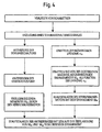
- Fig. 4
- ein Flußdiagramm eines Verfahrens zum Betreiben einer elektrischen Maschine in einem Antriebssystem.
-verlauf der elektrischen Maschine werden der zum Zeitpunkt t3 vorliegenden Drehzahl angepaßt. Analog zum oben beschriebenen Fall werden die Drehmomente des Verbrennungsmotors 1 und der elektrischen Maschine 3 derart überlagert, daß die in der Fig. 3 gezeigten Kurven K3 resultieren. Zum Zeitpunkt t5 erlischt die Wirkung der elektrischen Maschine 3, d.h. ihr Drehmoment ist auf Null abgesunken.
Claims (16)
- Antriebssystem für ein Kraftfahrzeug, mit:einem Verbrennungsmotor (1);einer Einrichtung (8) zur Schubabschaltung des Verbrennungsmotors (1);wenigstens einer elektrischen Maschine (3), die mit dem Verbrennungsmotor (1) gekoppelt ist und dazu eingerichtet ist, beim Aktivieren und Deaktivieren der Schubabschaltung den damit einhergehenden Beschleunigungsruck durch Aufbringen eines Drehmomentes zu vermindern;wobei die ruckvermindernde Wirkung der elektrischen Maschine (3) durch ein Aktivierungs- bzw. Deaktivierungssignal der Schubabschaltung gesteuert wird.
- Antriebssystem nach Anspruch 1, bei welchem die ruckvermindernde Wirkung bei einer Aktivierung der Schubabschaltung aufgrund folgender Bedingung herbeigeführt wird: das Fahrzeug benötigt keine Antriebsleistung und der Verbrennungsmotor (1) weist eine vorbestimmte Mindestdrehzahl auf.
- Antriebssystem nach Anspruch 1 oder 2, bei welchem die ruckvermindernde Wirkung bei einer Deaktivierung der Schubabschaltung aufgrund folgender Bedingung herbeigeführt wird: die Drehzahl des Verbrennungsmotors (1) sinkt auf einen vorbestimmten Mindestwert ab.
- Antriebssystem nach einem der Ansprüche 1 bis 3, bei welchem die ruckvermindernde Wirkung bei einer Deaktivierung der Schubabschaltung aufgrund folgender Bedingung herbeigeführt wird: das Fahrzeug benötigt zusätzliche Antriebsleistung.
- Antriebssystem nach einem der Ansprüche 1 bis 4, bei welchem die ruckvermindernde Wirkung bei einer Aktivierung der Schubabschaltung aufgrund folgender Bedingung herbeigeführt wird: das Fahrzeug erreicht eine vorbestimmte Höchstgeschwindigkeit.
- Antriebssystem nach einem der Ansprüche 1 bis 5, bei welchem die ruckvermindernde Wirkung bei einer Aktivierung der Schubabschaltung aufgrund folgender Bedingung herbeigeführt wird: der Verbrennungsmotor (1) erreicht eine vorbestimmte Höchstdrehzahl.
- Antriebssystem nach einem der Ansprüche 1 bis 6, bei welchem die elektrische Maschine (3) koaxial zur Kurbelwelle (2) des Verbrennungsmotors (1) oder zu einer Antriebswelle (2) angeordnet ist und mit dem Verbrennungsmotor (1) mitdreht.
- Antriebssystem nach Anspruch 7, bei welchem die elektrische Maschine (3) als Starter/Generator ausgebildet ist.
- Antriebssystem nach Anspruch 7 oder 8, bei welchem die elektrische Maschine (3) als wechselrichter-gesteuerte Drehstrommaschine ausgebildet ist.
- Antriebssystem nach Anspruch 9, bei welchem die elektrische Maschine (3) von einem Wechselrichter (10) mit Gleichspannungs-Zwischenkreis (10 B) gespeist wird, der ein erhöhtes Spannungsniveau aufweist, wobei ein Energiespeicher (11) auf dem erhöhten Spannungsniveau angeordnet ist und Energie für die Funktion der ruckvermindernden Wirkung zur Verfügung stellt bzw. aufnimmt.
- Verfahren zum Betreiben eines Antriebssystems für ein Kraftfahrzeug mit Verbrennungsmotor (1), einer Einrichtung (8)zur Schubabschaltung des Verbrennungsmotors (1) und wenigstens einer elektrischen Maschine (3), die mit dem Verbrennungsmotor (1) gekoppelt ist und dazu eingerichtet ist, beim Aktivieren und Deaktivieren der Schubabschaltung den damit einhergehenden Beschleunigungsruck durch Aufbringen eines Drehmomentes zu vermindern, wobei die ruckvermindernde Wirkung der elektrischen Maschine (3) durch ein Aktivierungs- bzw. Deaktivierungssignal der Schubabschaltung gesteuert wird.
- Verfahren nach Anspruch 11, bei welchem die ruckvermindernde Wirkung bei einer Aktivierung der Schubabschaltung aufgrund folgender Bedingung herbeigeführt wird: das Fahrzeug benötigt keine Antriebsleistung und der Verbrennungsmotor (1) weist eine vorbestimmte Mindestdrehzahl auf.
- Verfahren nach Anspruch 11 oder 12, bei welchem die ruckvermindernde Wirkung bei einer Deaktivierung der Schubabschaltung aufgrund folgender Bedingung herbeigeführt wird: die Drehzahl des Verbrennungsmotors (1) sinkt auf einen vorbestimmten Mindestwert ab.
- Verfahren nach einem der Ansprüche 11 bis 13, bei welchem die ruckvermindernde Wirkung bei einer Deaktivierung der Schubabschaltung aufgrund folgender Bedingung herbeigeführt wird: das Fahrzeug benötigt zusätzliche Antriebsleistung.
- Verfahren nach einem der Ansprüche 11 bis 14, bei welchem die ruckvermindernde Wirkung bei einer Aktivierung der Schubabschaltung aufgrund folgender Bedingung herbeigeführt wird: das Fahrzeug erreicht eine vorbestimmte Höchstgeschwindigkeit.
- Verfahren nach einem der Ansprüche 11 bis 15, bei welchem die ruckvermindernde Wirkung bei einer Aktivierung der Schubabschaltung aufgrund folgender Bedingung herbeigeführt wird: der Verbrennungsmotor (1) erreicht eine vorbestimmte Höchstdrehzahl.
Applications Claiming Priority (3)
| Application Number | Priority Date | Filing Date | Title |
|---|---|---|---|
| DE19839315 | 1998-08-28 | ||
| DE19839315A DE19839315A1 (de) | 1998-08-28 | 1998-08-28 | Antriebssystem für ein Kraftfahrzeug sowie Verfahren zum Betreiben eines Antriebssystems |
| PCT/EP1999/005527 WO2000012885A1 (de) | 1998-08-28 | 1999-07-30 | Antriebssystem für ein kraftfahrzeug sowie verfahren zum betreiben eines antriebssystems |
Publications (2)
| Publication Number | Publication Date |
|---|---|
| EP1108128A1 EP1108128A1 (de) | 2001-06-20 |
| EP1108128B1 true EP1108128B1 (de) | 2002-10-09 |
Family
ID=7879098
Family Applications (1)
| Application Number | Title | Priority Date | Filing Date |
|---|---|---|---|
| EP99940098A Expired - Lifetime EP1108128B1 (de) | 1998-08-28 | 1999-07-30 | Antriebssystem für ein kraftfahrzeug sowie verfahren zum betreiben eines antriebssystems |
Country Status (3)
| Country | Link |
|---|---|
| EP (1) | EP1108128B1 (de) |
| DE (2) | DE19839315A1 (de) |
| WO (1) | WO2000012885A1 (de) |
Cited By (2)
| Publication number | Priority date | Publication date | Assignee | Title |
|---|---|---|---|---|
| DE102007016515A1 (de) | 2007-04-05 | 2008-10-09 | Daimler Ag | Verfahren zur Steuerung eines Antriebssystems für ein Kraftfahrzeug |
| SE1751214A1 (en) * | 2017-10-02 | 2019-04-03 | Scania Cv Ab | Method and system for controlling at least one electrical machine |
Families Citing this family (10)
| Publication number | Priority date | Publication date | Assignee | Title |
|---|---|---|---|---|
| SE516313C2 (sv) * | 2000-09-07 | 2001-12-17 | Volvo Personvagnar Ab | Förfarande och anordning för styrning av ett drivssystem |
| JP3589198B2 (ja) * | 2000-12-25 | 2004-11-17 | トヨタ自動車株式会社 | 駆動系統の制御装置 |
| US6581705B2 (en) * | 2001-06-29 | 2003-06-24 | Ford Global Technologies, Llc | Method for starting an engine in a parallel hybrid electric vehicle |
| DE102004013812A1 (de) * | 2004-03-20 | 2005-10-06 | Volkswagen Ag | Verfahren zum Betreiben eines Hybrid-Kraftfahrzeugs |
| DE102004062012A1 (de) | 2004-12-23 | 2006-07-20 | Robert Bosch Gmbh | Verfahren zum Betreiben eines Hybridfahrzeugs |
| DE102005032670A1 (de) * | 2005-07-13 | 2007-02-01 | Iav Gmbh Ingenieurgesellschaft Auto Und Verkehr | Verfahren zur Steuerung der Antriebsleistungsverteilung in einem Kraftfahrzeug mit Hybridantrieb |
| DE102005039920B4 (de) * | 2005-08-24 | 2018-06-07 | Zf Friedrichshafen Ag | Verfahren zum Abschalten des Verbrennungsmotors bei einem mit einem elektrodynamischen Antriebssystem ausgerüsteten Fahrzeug |
| WO2009052839A1 (de) * | 2007-10-18 | 2009-04-30 | Fev Motorentechnik Gmbh | Hybridantrieb mit dekompressionseinrichtung |
| DE102021006520B3 (de) | 2021-05-07 | 2022-09-01 | Bayerische Motoren Werke Aktiengesellschaft | Geräuschminderung bei einem Getriebe eines elektrischen Fahrzeugantriebs |
| DE102021111908B3 (de) | 2021-05-07 | 2022-09-01 | Bayerische Motoren Werke Aktiengesellschaft | Geräuschminderung bei einem Getriebe eines elektrischen Fahrzeugantriebs |
Family Cites Families (6)
| Publication number | Priority date | Publication date | Assignee | Title |
|---|---|---|---|---|
| DE3246230A1 (de) * | 1982-12-14 | 1984-06-14 | Volkswagenwerk Ag | Getriebeanordnung |
| DE3814484A1 (de) | 1987-04-29 | 1988-11-17 | Erich Mai | Dieselmotoraggregat |
| SE500329C2 (sv) * | 1990-04-23 | 1994-06-06 | Volvo Ab | Anordning för att minska risken för motorstopp hos en bilmotor |
| US5315485A (en) | 1992-09-29 | 1994-05-24 | Mcnc | Variable size capture pads for multilayer ceramic substrates and connectors therefor |
| DE19532128A1 (de) * | 1995-08-31 | 1997-03-06 | Clouth Gummiwerke Ag | Antriebssystem, insbesondere für ein Kraftfahrzeug, und Verfahren zum Betreiben desselben |
| DE19648055A1 (de) * | 1996-11-20 | 1998-06-04 | Siemens Ag | Antriebsstrangsteuerung für ein Kraftfahrzeug |
-
1998
- 1998-08-28 DE DE19839315A patent/DE19839315A1/de not_active Withdrawn
-
1999
- 1999-07-30 EP EP99940098A patent/EP1108128B1/de not_active Expired - Lifetime
- 1999-07-30 DE DE59903056T patent/DE59903056D1/de not_active Expired - Fee Related
- 1999-07-30 WO PCT/EP1999/005527 patent/WO2000012885A1/de not_active Ceased
Cited By (2)
| Publication number | Priority date | Publication date | Assignee | Title |
|---|---|---|---|---|
| DE102007016515A1 (de) | 2007-04-05 | 2008-10-09 | Daimler Ag | Verfahren zur Steuerung eines Antriebssystems für ein Kraftfahrzeug |
| SE1751214A1 (en) * | 2017-10-02 | 2019-04-03 | Scania Cv Ab | Method and system for controlling at least one electrical machine |
Also Published As
| Publication number | Publication date |
|---|---|
| EP1108128A1 (de) | 2001-06-20 |
| WO2000012885A1 (de) | 2000-03-09 |
| DE59903056D1 (de) | 2002-11-14 |
| DE19839315A1 (de) | 2000-03-09 |
Similar Documents
| Publication | Publication Date | Title |
|---|---|---|
| EP1068090B1 (de) | Hybridantriebssystem für ein kraftfahrzeug, sowie verfahren zum betreiben desselben in der anfahrphase | |
| DE69610360T2 (de) | Hybridfahrzeug und sein Regelverfahren | |
| DE60029905T2 (de) | Motorstartsteuerung für Fahrzeuge | |
| EP1458586B1 (de) | Vorrichtung und verfahren zur regelung der fahrgeschwindigkeit eines fahrzeugs | |
| EP3419848B1 (de) | Antriebssystem für ein hybridfahrzeug und verfahren zum betreiben eines solchen | |
| EP1814754B2 (de) | Verfahren zur steuerung eines betriebs eines hybridkraftfahrzeugs sowie hybridfahrzeug | |
| DE69214602T2 (de) | Antriebsregelvorrichtung für ein in Folge geschaltetes Hybridfahrzeug | |
| EP1320472B1 (de) | Antriebsstrangsteuerung für ein kraftfahrzeug mit mindestens zwei antriebsaggregaten und einem getriebe | |
| EP1108128B1 (de) | Antriebssystem für ein kraftfahrzeug sowie verfahren zum betreiben eines antriebssystems | |
| DE2943554A1 (de) | Hybrid-antrieb fuer ein fahrzeug, insbesondere kraftfahrzeug | |
| EP0830968A1 (de) | Verfahren zum Betrieb eines nichtspurgebundenen Hybridfahrzeuges | |
| DE3321433A1 (de) | Antriebsmotorsystem fuer kraftfahrzeuge | |
| DE60301978T2 (de) | System und Verfahren zur Steuerung der Stromversorgung eines Hybrid-Fahrzeugs | |
| DE10236010A1 (de) | Steuereinrichtung sowie Verfahren für ein Fahrzeug, welches mit einem Verbrennungsmotor ausgerüstet ist | |
| DE102004028713B4 (de) | Leistungssteuerungssystem für ein Fahrzeug, in welchem ein Verbrennungsmotor mit Lader montiert ist | |
| DE102009037190A1 (de) | Steuervorrichtung für Elektrofahrzeuge | |
| DE102008049225A1 (de) | Verfahren und Vorrichtung zur Optimierung eines Betriebs eines Verbundes aus einem Verbrennungsmotor und einem Generator in einem seriellen Hybridantrieb | |
| EP2197721A2 (de) | Leerlaufdrehzahlregelung bei einem hybridfahrzeug | |
| EP3515741A2 (de) | Verfahren zum betreiben eines hybridfahrzeugs | |
| DE102005037713A1 (de) | Antriebsstrang für ein Kraftfahrzeug sowie Verfahren zum Betreiben eines Antriebsstranges | |
| DE69715438T2 (de) | Vorrichtung und verfahren zum einschalten durch einen motor angetriebener hilfsaggregate | |
| EP2613991A1 (de) | Verfahren zur steuerung eines antriebssystems | |
| WO2020088818A1 (de) | Verfahren und antriebssteuergerät zum betrieb von zumindest zwei elektrischen antriebsmaschinen bei einer laständerung sowie kraftfahrzeug mit einem antriebssteuergrät | |
| DE69502623T2 (de) | Antriebsvorrichtung für hilfswerkzeuge einer fahrzeugbrennkraftmaschine | |
| DE102005039929B4 (de) | Verfahren zum Rangieren eines mit einem elektrodynamischen Antriebssystem ausgerüsteten Fahrzeugs |
Legal Events
| Date | Code | Title | Description |
|---|---|---|---|
| PUAI | Public reference made under article 153(3) epc to a published international application that has entered the european phase |
Free format text: ORIGINAL CODE: 0009012 |
|
| 17P | Request for examination filed |
Effective date: 20001127 |
|
| AK | Designated contracting states |
Kind code of ref document: A1 Designated state(s): AT BE CH CY DE DK ES FI FR GB GR IE IT LI LU MC NL PT SE |
|
| 17Q | First examination report despatched |
Effective date: 20010719 |
|
| GRAG | Despatch of communication of intention to grant |
Free format text: ORIGINAL CODE: EPIDOS AGRA |
|
| GRAG | Despatch of communication of intention to grant |
Free format text: ORIGINAL CODE: EPIDOS AGRA |
|
| GRAH | Despatch of communication of intention to grant a patent |
Free format text: ORIGINAL CODE: EPIDOS IGRA |
|
| GRAH | Despatch of communication of intention to grant a patent |
Free format text: ORIGINAL CODE: EPIDOS IGRA |
|
| GRAA | (expected) grant |
Free format text: ORIGINAL CODE: 0009210 |
|
| AK | Designated contracting states |
Kind code of ref document: B1 Designated state(s): DE FR GB IT |
|
| REG | Reference to a national code |
Ref country code: GB Ref legal event code: FG4D Free format text: NOT ENGLISH |
|
| REG | Reference to a national code |
Ref country code: IE Ref legal event code: FG4D Free format text: GERMAN |
|
| REF | Corresponds to: |
Ref document number: 59903056 Country of ref document: DE Date of ref document: 20021114 |
|
| GBT | Gb: translation of ep patent filed (gb section 77(6)(a)/1977) |
Effective date: 20030204 |
|
| ET | Fr: translation filed | ||
| REG | Reference to a national code |
Ref country code: IE Ref legal event code: FD4D Ref document number: 1108128E Country of ref document: IE |
|
| PLBE | No opposition filed within time limit |
Free format text: ORIGINAL CODE: 0009261 |
|
| STAA | Information on the status of an ep patent application or granted ep patent |
Free format text: STATUS: NO OPPOSITION FILED WITHIN TIME LIMIT |
|
| 26N | No opposition filed |
Effective date: 20030710 |
|
| PGFP | Annual fee paid to national office [announced via postgrant information from national office to epo] |
Ref country code: GB Payment date: 20040630 Year of fee payment: 6 |
|
| PGFP | Annual fee paid to national office [announced via postgrant information from national office to epo] |
Ref country code: FR Payment date: 20040708 Year of fee payment: 6 |
|
| PGFP | Annual fee paid to national office [announced via postgrant information from national office to epo] |
Ref country code: DE Payment date: 20040713 Year of fee payment: 6 |
|
| PG25 | Lapsed in a contracting state [announced via postgrant information from national office to epo] |
Ref country code: IT Free format text: LAPSE BECAUSE OF NON-PAYMENT OF DUE FEES Effective date: 20050730 Ref country code: GB Free format text: LAPSE BECAUSE OF NON-PAYMENT OF DUE FEES Effective date: 20050730 |
|
| PG25 | Lapsed in a contracting state [announced via postgrant information from national office to epo] |
Ref country code: DE Free format text: LAPSE BECAUSE OF NON-PAYMENT OF DUE FEES Effective date: 20060201 |
|
| GBPC | Gb: european patent ceased through non-payment of renewal fee |
Effective date: 20050730 |
|
| PG25 | Lapsed in a contracting state [announced via postgrant information from national office to epo] |
Ref country code: FR Free format text: LAPSE BECAUSE OF NON-PAYMENT OF DUE FEES Effective date: 20060331 |
|
| REG | Reference to a national code |
Ref country code: FR Ref legal event code: ST Effective date: 20060331 |