EP1107420A2 - Stromversorgungsschaltung - Google Patents
Stromversorgungsschaltung Download PDFInfo
- Publication number
- EP1107420A2 EP1107420A2 EP00310366A EP00310366A EP1107420A2 EP 1107420 A2 EP1107420 A2 EP 1107420A2 EP 00310366 A EP00310366 A EP 00310366A EP 00310366 A EP00310366 A EP 00310366A EP 1107420 A2 EP1107420 A2 EP 1107420A2
- Authority
- EP
- European Patent Office
- Prior art keywords
- storage device
- power storage
- power
- power supply
- voltage
- Prior art date
- Legal status (The legal status is an assumption and is not a legal conclusion. Google has not performed a legal analysis and makes no representation as to the accuracy of the status listed.)
- Withdrawn
Links
- 238000007599 discharging Methods 0.000 claims description 15
- 230000000737 periodic effect Effects 0.000 claims description 12
- 238000000034 method Methods 0.000 claims description 11
- 239000003990 capacitor Substances 0.000 claims description 6
- 230000004044 response Effects 0.000 claims description 2
- 230000001413 cellular effect Effects 0.000 description 7
- 230000001681 protective effect Effects 0.000 description 6
- 238000010586 diagram Methods 0.000 description 3
- 229910001416 lithium ion Inorganic materials 0.000 description 3
- HBBGRARXTFLTSG-UHFFFAOYSA-N Lithium ion Chemical compound [Li+] HBBGRARXTFLTSG-UHFFFAOYSA-N 0.000 description 1
- OJIJEKBXJYRIBZ-UHFFFAOYSA-N cadmium nickel Chemical compound [Ni].[Cd] OJIJEKBXJYRIBZ-UHFFFAOYSA-N 0.000 description 1
- 230000000694 effects Effects 0.000 description 1
- 229910052987 metal hydride Inorganic materials 0.000 description 1
- 229910044991 metal oxide Inorganic materials 0.000 description 1
- 150000004706 metal oxides Chemical class 0.000 description 1
- 238000010295 mobile communication Methods 0.000 description 1
- 238000012986 modification Methods 0.000 description 1
- 230000004048 modification Effects 0.000 description 1
- 229910052759 nickel Inorganic materials 0.000 description 1
- PXHVJJICTQNCMI-UHFFFAOYSA-N nickel Substances [Ni] PXHVJJICTQNCMI-UHFFFAOYSA-N 0.000 description 1
- -1 nickel metal hydride Chemical class 0.000 description 1
- 239000004065 semiconductor Substances 0.000 description 1
Images

Classifications
-
- H—ELECTRICITY
- H02—GENERATION; CONVERSION OR DISTRIBUTION OF ELECTRIC POWER
- H02J—CIRCUIT ARRANGEMENTS OR SYSTEMS FOR SUPPLYING OR DISTRIBUTING ELECTRIC POWER; SYSTEMS FOR STORING ELECTRIC ENERGY
- H02J7/00—Circuit arrangements for charging or depolarising batteries or for supplying loads from batteries
- H02J7/34—Parallel operation in networks using both storage and other DC sources, e.g. providing buffering
- H02J7/345—Parallel operation in networks using both storage and other DC sources, e.g. providing buffering using capacitors as storage or buffering devices
-
- G—PHYSICS
- G01—MEASURING; TESTING
- G01R—MEASURING ELECTRIC VARIABLES; MEASURING MAGNETIC VARIABLES
- G01R31/00—Arrangements for testing electric properties; Arrangements for locating electric faults; Arrangements for electrical testing characterised by what is being tested not provided for elsewhere
- G01R31/36—Arrangements for testing, measuring or monitoring the electrical condition of accumulators or electric batteries, e.g. capacity or state of charge [SoC]
- G01R31/382—Arrangements for monitoring battery or accumulator variables, e.g. SoC
-
- H—ELECTRICITY
- H02—GENERATION; CONVERSION OR DISTRIBUTION OF ELECTRIC POWER
- H02J—CIRCUIT ARRANGEMENTS OR SYSTEMS FOR SUPPLYING OR DISTRIBUTING ELECTRIC POWER; SYSTEMS FOR STORING ELECTRIC ENERGY
- H02J7/00—Circuit arrangements for charging or depolarising batteries or for supplying loads from batteries
- H02J7/0029—Circuit arrangements for charging or depolarising batteries or for supplying loads from batteries with safety or protection devices or circuits
-
- H—ELECTRICITY
- H02—GENERATION; CONVERSION OR DISTRIBUTION OF ELECTRIC POWER
- H02J—CIRCUIT ARRANGEMENTS OR SYSTEMS FOR SUPPLYING OR DISTRIBUTING ELECTRIC POWER; SYSTEMS FOR STORING ELECTRIC ENERGY
- H02J7/00—Circuit arrangements for charging or depolarising batteries or for supplying loads from batteries
- H02J7/0047—Circuit arrangements for charging or depolarising batteries or for supplying loads from batteries with monitoring or indicating devices or circuits
-
- H—ELECTRICITY
- H02—GENERATION; CONVERSION OR DISTRIBUTION OF ELECTRIC POWER
- H02J—CIRCUIT ARRANGEMENTS OR SYSTEMS FOR SUPPLYING OR DISTRIBUTING ELECTRIC POWER; SYSTEMS FOR STORING ELECTRIC ENERGY
- H02J7/00—Circuit arrangements for charging or depolarising batteries or for supplying loads from batteries
- H02J7/007—Regulation of charging or discharging current or voltage
- H02J7/00712—Regulation of charging or discharging current or voltage the cycle being controlled or terminated in response to electric parameters
- H02J7/00714—Regulation of charging or discharging current or voltage the cycle being controlled or terminated in response to electric parameters in response to battery charging or discharging current
-
- Y—GENERAL TAGGING OF NEW TECHNOLOGICAL DEVELOPMENTS; GENERAL TAGGING OF CROSS-SECTIONAL TECHNOLOGIES SPANNING OVER SEVERAL SECTIONS OF THE IPC; TECHNICAL SUBJECTS COVERED BY FORMER USPC CROSS-REFERENCE ART COLLECTIONS [XRACs] AND DIGESTS
- Y02—TECHNOLOGIES OR APPLICATIONS FOR MITIGATION OR ADAPTATION AGAINST CLIMATE CHANGE
- Y02B—CLIMATE CHANGE MITIGATION TECHNOLOGIES RELATED TO BUILDINGS, e.g. HOUSING, HOUSE APPLIANCES OR RELATED END-USER APPLICATIONS
- Y02B40/00—Technologies aiming at improving the efficiency of home appliances, e.g. induction cooking or efficient technologies for refrigerators, freezers or dish washers
Definitions
- the present invention relates to a power supply circuit comprising a first power storage device.
- the portable electronic devices include mobile communication devices such as cellular phones, notebook type computers, camcorders, MP3 and the like.
- a portable electronic device having a built-in battery pack is operable even at a place where a commercial power supply is not available.
- rechargeable (secondary) batteries that can be recycled by charging, such as nickel cadmium (NiCd), nickel metal hydride (NiMH), or lithium ion (Li-ion) batteries, are used as the built-in battery of a portable electronic device.
- the built-in battery is charged by external AC power in a state that a battery pack is mounted in a system, i.e., a portable electronic device.
- a feature of the portable electronic device is to include a digital load made up of digital circuits.
- FIG 1 shows a power supply system of a portable electronic device having a digital load.
- a power supply unit 13 for supplying power to various parts of the portable electronic device is interposed between a rechargeable battery 11 and a load 15.
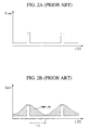
- the load 15 is a digital load and requires pulse-like power shown in Figure 2A.
- the digital load consumes current such that pulse waves are generated in units of a predetermined cycle.
- rechargeable (secondary) batteries have a difficulty in rapidly discharging, they cannot follow a pulse-like current characteristic rapidly, as shown in Figure 2B.
- pulse power periodic pulse power
- the present inventors have proposed a method in which while using a power storage device capable of rapidly discharging as a main power supply of a digital load, a conventional battery is used as an auxiliary power supply for the purpose of preventing a sharp voltage drop occurring at the power storage device in the event of system overload.
- a power supply circuit is characterised by a second power storage device, switching means and control means, wherein the second power storage device has a better ability to supply pulsed current to a load than the first power storage means and the control means is operable to sense the voltage across the second power storage device and control the switching means in response thereto such that when said sensed voltage is above a threshold, power to supplied by the circuit from the second power storage device only and otherwise from both the first and second power storage devices.
- the first power storage device is a battery and the second power storage device is a an electrolytic double layer capacitor.
- a power supply controller connected to a digital variable load requesting periodic pulse power, for controlling power supplied to the digital variable load, the power supply controller including a first power storage device as a main power supply, for supplying the periodic pulse power to the variable load, the first power storage device capable of rapidly discharging to rapidly follow the periodic pulse power of the variable load; a second power storage device for supplying the first power storage device with the power for compensating for a voltage drop when a sharp voltage drop occurs to the first power storage device due to overload; a plurality of power supply lines disposed between the first and second power storage devices; and a control unit for sensing an output voltage of the first power storage device and controlling to open and closed states of the plurality of power supply lines to supply the second power storage device with the power stored in the second power storage device if the sensed voltage is dropped to a reference voltage level or below.
- the first power storage device is preferably an electrolytic double layer capacitor (EDLC) and the second power storage device is preferably either a rechargeable secondary battery or a primary battery.
- EDLC electrolytic double layer capacitor
- one or more power supply lines may be disposed between the first power storage device and the second power storage device, and one or more switching elements may be installed along the power supply lines.
- the control unit connects the first power storage device and the second power storage device by performing switching control of the switching elements.
- first and second power supply lines may be disposed between the first power storage device and the second power storage device, the first power supply line may directly connect the first power storage device and the second power storage device, and the second power supply line may connect the first power storage device and the second power storage device through an internal switching module of the control unit.
- the first power supply line may directly connect the first power storage device and the second power storage device
- the second power supply line may connect the first power storage device and the second power storage device through an internal switching module of the control unit.
- the power supply controller may further include a third power storage device for storing emergency power to be supplied to the second power storage device when the load requests emergency power in a state where the first and second power storage devices are completely discharged.
- the third power storage device for storing emergency power is an EDLC having a smaller capacity than the first power storage device and is connected to the second power storage device through switching elements.
- the power supply controlling method therefor includes the steps of sensing the voltage level of the second power storage device and connecting the second power storage device with an external power supply if the sensed voltage level is lowered to a level in which charging is required, sensing the voltage level of the first power storage device and determining whether there is a voltage drop in the first power storage device, if it is determined in the determining step that there is a voltage drop in the first power storage device, determining a voltage drop value, and charging either the first power supply line or the second power supply line based on the determined voltage drop value and compensating for the voltage drop of the first power storage device.
- a power supply can be provided which quickly adapts to a power characteristic of a digital load.
- Embodiments of the present invention can provide a power supply controller and a power supply controlling method therefor, by which a sharp voltage drop which is an impediment to stable power supply can be prevented, and by which emergency power supply is allowed even in a state that a main power supply is completely discharged.
- any terms or words used in the present specifications and claims should not be taken in a limited way and interpreted ordinarily and lexicographically, but interpreted in the sense and concept that go with the technical thoughts of the present invention, based on the principle that an inventor is authorized to define a term appropriately in order to explain his or her invention in the best possible way. Accordingly, the embodiment described in the specifications herein and the composition illustrated in the drawings herein are nothing more than an embodiment deemed most desirable, and do not represent the whole technical thoughts of the present invention, allowing for the possibility of a variety of equivalents that can replace the embodiments provided herein and variant examples.
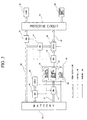
- the power supply controller includes a battery 50, a control unit 60, a protective circuit 70, a first electrolytic double layer capacitor (EDLC1) 90, a second electric double layer capacitor (EDLC2) 80 and a plurality of switching elements 51, 52, 53, 54 and 55.
- EDLC1 electrolytic double layer capacitor
- EDLC2 electric double layer capacitor
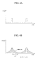
- a digital variable load 40 having a current consumption characteristic shown in Figure 4A and an external power supply 30 such as a commercial AC power supply are connected to the protective circuit 70.
- the battery 50 is a kind of a power storage device for storing electrical energy and discharging, and a primary battery, a rechargeable secondary battery, a solar battery and the like can be used as the battery 50. In this embodiment, a rechargeable secondary battery is used as the battery 50.
- the EDLC2 80 is also a kind of a power storage device and is capable of rapidly charging and discharging compared to primary and secondary batteries.
- the EDLC2 80 is suitably used as a main power supply of a digital load requesting pulse-like power.
- the EDLC1 90 is the same as the EDLC2 80, except for its capacitance. However, since the capacitance of the EDLC1 90 is smaller than that of the battery 50 or the EDLC2 80, the EDLC1 90 is used for emergency power supply in this embodiment.
- the control unit 60 includes a voltage sensor 63 for sensing the voltage levels of the battery 50, the EDLC1 90 and the EDLC2 80, a switching controller 61 for controlling the turn-on and turn-off of the plurality of switching elements (SW1, SW2, SW3, SW4 and SW5) 51, 52, 53, 54 and 55, and an internal switching module 62.
- the switching elements 51 through 55 switch a power supply line from an open state to a closed state in accordance with a switching control signal of the switching controller 61.
- the switching elements 51 through 55 are preferably constituted by semiconductor devices such as metal-oxide semiconductor-field effect transistors (MOS-FETs) that consume a relatively small amount of power.
- MOS-FETs metal-oxide semiconductor-field effect transistors
- the protective circuit 70 protects a power storage device from over-charging or over-discharging caused during charging or discharging of the EDLC1 or EDLC2.
- the protective circuit 70 is essentially needed.
- the protective circuit 70 may not be used.
- the load 40 is a digital load incorporated in a portable electronic device and, in particular, is a variable load having a pulse power characteristic shown in Figure 4A.
- the external power supply 30 generally implies a commercial AC power supply.
- the commercial AC power supply also includes an self-generator disclosed in Korean Patent Application Nos. 98-43924 and 99-43024 filed by the present inventors.
- the battery 50 and the EDLC2 80 are connected to each other by first and second power supply lines 56 and 57.
- the power supply lines 56 and 57 include each two switching elements.
- the switching elements (SW3 and SW4) 53 and 54 are installed along the first power supply line 56 and the switching elements (SW1 and SW2) 51 and 52 are installed along the second power supply line 57.
- control unit 60 is disposed between the switching elements (SW1 and SW2) 51 and 52 of the second power supply line 57.
- the second power supply line 57 connects the battery 50 and the EDLC2 80 via its two switching elements (SW1 and SW2) 51 and 52 and the internal switching module 62 of the control unit 60.
- the internal switching module 62 of the control unit 60 serves to limit the current discharged by the battery 50 to the predetermined critical value.
- the current flowing in the second power supply line 57 has a limited magnitude compared to the current flowing in the first power supply line 56.
- the switching element (SW4) 54 of the first power supply line 56 is disposed between the battery 50 and the EDLC2 80, and the switching element (SW3) 53 is disposed between the battery 50 and the protective circuit 70.
- the EDLC1 90 which is a spare power supply for supplying emergency power, is connected to the battery 50 through the switching element (SW5) 55.
- SW5 55 switching element
- the plurality of switching elements 51 through 55 are controlled by the switching controller 61 of the control unit 60, as indicated by dotted lines in Figure 3, that is, control lines.
- the voltage sensor 63 of the control unit 60 checks the voltage levels of the power storage devices 50, 80 and 90 at times through sensing lines indicated by solid lines in Figure 3.
- the power discharged from the battery 50, the EDLC1 90 and the EDLC2 80 or charged from the external power supply 30 are supplied through the power supply lines 56, 57 and 58 shown in Figure 3.
- the off-state of a switching element refers to the open state of a power supply line.
- the digital variable load 40 requests pulse power shown in Figure 4A in a state where all the switching elements 51 through 55 are turned off, that is, under general load conditions, the EDLC2 80 capable of rapidly discharging, discharges the current I EDLC2 rapidly following the pulse power of the variable load 40, as shown in Figure 4B.
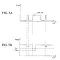
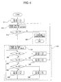
- control unit 60 of the present invention compensates for a sharp voltage drop occurring to the main power supply, that is, the EDLC2, through the procedure shown in Figure 6.
- V BATT denotes an output voltage of the battery 50
- V E2 denotes an output voltage of the EDLC2 80
- V 1 , V 2 , V 3 and V 4 denote reference voltages stored in an internal memory (not shown) of the control unit 60.
- the reference voltages may change variably according to the kind of the load.
- step S20 the procedure for the control unit 60 to perform switching control is largely divided into a charging mode performing step (step S20) and a discharging mode performing step (step S30).
- the switching elements (SW1 and SW2) 51 and 52 are turned on, while the switching elements (SW3 and SW4) 53 and 54 are turned off (step S11).
- the voltage sensor 63 of the control unit 60 senses the voltage level V BATT of the battery 50 (step S12).
- the sensed voltage level V BATT is compared with the reference voltage V 1 , for example, 3.0 V in the case of a cellular phone (step S13).
- step S13 if the voltage level V BATT of the battery 50 is lower than the reference voltage V 1 , the control unit 60 charges the battery 50 such that the switching element (SW3) 53 is turned on and the other switching elements (SW1, SW2, SW4 and SW5) 51, 52, 54 and 55 are kept off (step S20).
- step S13 If the voltage level V BATT of the battery 50 is higher than the reference voltage V 1 in the step S13, it is determined that the battery 50 is fully charged to proceed to the discharging mode performing step followed by the step S30.
- the control unit 60 senses the voltage V E2 of the EDLC2 80 to execute the discharging mode control operation (step S31).
- the control unit 60 determines that the present state is a normal discharging mode in which there is no voltage drop (step S32). Thus, the switching controller 61 of the control unit 60 turns off all the switching elements (SW1, SW2, SW3, SW4 and SW5) 51, 52, 53, 54 and 55 (step S37), and then the routine goes back to the step S12. (ii) V 3 ⁇ V E2 ⁇ V 2
- the control unit 60 determines that sufficient power can be supplied to the load 40 by using only the ELDC 2 80 even if there is a small amount of a voltage drop in the EDLC2 80 (step S33).
- the switching controller 61 of the control unit 60 turns off all the switching elements (SW1, SW2, SW3, SW4 and SW5) 51, 52, 53, 54 and 55 (step S387), and then the routine goes back to the step S12.
- the control unit 60 determines that there is a little voltage drop in the EDLC2 80 due to overload (step S34). Thus, the switching controller 61 of the control unit 60 turns on the switching elements (SW1 and SW2) 51 and 52 and turns off the switching elements (SW3 and SW4) 53 and 54 to open the first power supply line 57 (step S35). (iv) V E2 ⁇ V 4
- the control unit 60 determines that there is suddenly a large voltage drop in the EDLC2 80 due to severe overloads (step S34).
- the switching controller 61 of the control unit 60 turns off the switching elements (SW1 and SW2) 51 and 52 and turns on the switching elements (SW3 and SW4) 53 and 54 to open the second power supply line 57 (step S36).
- the battery discharged current supplied through the first power supply line 57 is limited to a predetermined critical value through the internal switching module 62 of the control unit 60, the battery discharged current is smaller than the current supplied through the second power supply line 56.
- the control unit 60 opens the first power supply line 57. If there is a sharp voltage drop in the EDLC2 80, the control unit 60 opens the second power supply line 56. In such a manner, the problem of a system, which may be caused due to a voltage drop, can be overcome.
- the power supply controller and the power supply controlling method according to the present invention allow a digital load to rapidly follow periodic pulse power. Also, according to the present invention, it is possible to effectively cope with a voltage drop occurring at a main power supply, which is caused due to a variation in the load. In particular, according to the present invention, the power utilization efficiency can be maximized by adjusting the magnitude of the current discharged by a battery according to either a gentle voltage drop or a sharp voltage drop. Further, the present invention enables emergency power supply requested by a load, even if EDLCs and a battery, serving as a main power supply, are completely discharged.
- the present invention can be applied to power supply systems for portable digital electronic devices which are driven by a battery, such as cellular phones, notebook computers, camcorders, MP3 or the like.
Landscapes
- Engineering & Computer Science (AREA)
- Power Engineering (AREA)
- Physics & Mathematics (AREA)
- General Physics & Mathematics (AREA)
- Charge And Discharge Circuits For Batteries Or The Like (AREA)
- Secondary Cells (AREA)
- Direct Current Feeding And Distribution (AREA)
Applications Claiming Priority (2)
| Application Number | Priority Date | Filing Date | Title |
|---|---|---|---|
| KR1019990054697A KR20000017774A (ko) | 1999-12-03 | 1999-12-03 | 디지털 전자기기의 전원공급 제어회로 및 전원공급 제어방법 |
| KR9954697 | 1999-12-03 |
Publications (1)
| Publication Number | Publication Date |
|---|---|
| EP1107420A2 true EP1107420A2 (de) | 2001-06-13 |
Family
ID=19623380
Family Applications (1)
| Application Number | Title | Priority Date | Filing Date |
|---|---|---|---|
| EP00310366A Withdrawn EP1107420A2 (de) | 1999-12-03 | 2000-11-22 | Stromversorgungsschaltung |
Country Status (7)
| Country | Link |
|---|---|
| US (1) | US20010002772A1 (de) |
| EP (1) | EP1107420A2 (de) |
| JP (1) | JP2001190032A (de) |
| KR (2) | KR20000017774A (de) |
| CN (1) | CN1305255A (de) |
| AU (1) | AU1420401A (de) |
| WO (1) | WO2001041282A1 (de) |
Cited By (22)
| Publication number | Priority date | Publication date | Assignee | Title |
|---|---|---|---|---|
| EP1363379A3 (de) * | 2002-05-13 | 2004-01-02 | Luxon Energy Devices Corporation | Leistungsmodul zur Erzeugung von Energieimpulsen unterschiedlicher Stärke |
| WO2005050812A1 (en) * | 2003-11-18 | 2005-06-02 | Victhom Human Bionics Inc. | Compact power supply |
| US7085123B2 (en) | 2004-12-07 | 2006-08-01 | Luxon Energy Devices Corporation | Power supply apparatus and power supply method |
| US7786699B2 (en) | 2005-01-25 | 2010-08-31 | Victhom Human Bionics, Inc. | Power supply charger and method of charging |
| US8323354B2 (en) | 2003-11-18 | 2012-12-04 | Victhom Human Bionics Inc. | Instrumented prosthetic foot |
| US8617254B2 (en) | 2004-03-10 | 2013-12-31 | Ossur Hf | Control system and method for a prosthetic knee |
| US8657886B2 (en) | 2004-02-12 | 2014-02-25 | össur hf | Systems and methods for actuating a prosthetic ankle |
| US8702811B2 (en) | 2005-09-01 | 2014-04-22 | össur hf | System and method for determining terrain transitions |
| US8814949B2 (en) | 2005-04-19 | 2014-08-26 | össur hf | Combined active and passive leg prosthesis system and a method for performing a movement with such a system |
| US9017419B1 (en) | 2012-03-09 | 2015-04-28 | össur hf | Linear actuator |
| US9060884B2 (en) | 2011-05-03 | 2015-06-23 | Victhom Human Bionics Inc. | Impedance simulating motion controller for orthotic and prosthetic applications |
| US9351854B2 (en) | 2005-09-01 | 2016-05-31 | össur hf | Actuator assembly for prosthetic or orthotic joint |
| US9358137B2 (en) | 2002-08-22 | 2016-06-07 | Victhom Laboratory Inc. | Actuated prosthesis for amputees |
| US9526636B2 (en) | 2003-11-18 | 2016-12-27 | Victhom Laboratory Inc. | Instrumented prosthetic foot |
| US9561118B2 (en) | 2013-02-26 | 2017-02-07 | össur hf | Prosthetic foot with enhanced stability and elastic energy return |
| US9649206B2 (en) | 2002-08-22 | 2017-05-16 | Victhom Laboratory Inc. | Control device and system for controlling an actuated prosthesis |
| US9949850B2 (en) | 2015-09-18 | 2018-04-24 | Össur Iceland Ehf | Magnetic locking mechanism for prosthetic or orthotic joints |
| US10195057B2 (en) | 2004-02-12 | 2019-02-05 | össur hf. | Transfemoral prosthetic systems and methods for operating the same |
| US10290235B2 (en) | 2005-02-02 | 2019-05-14 | össur hf | Rehabilitation using a prosthetic device |
| US10543109B2 (en) | 2011-11-11 | 2020-01-28 | Össur Iceland Ehf | Prosthetic device and method with compliant linking member and actuating linking member |
| US10575970B2 (en) | 2011-11-11 | 2020-03-03 | Össur Iceland Ehf | Robotic device and method of using a parallel mechanism |
| US11007072B2 (en) | 2007-01-05 | 2021-05-18 | Victhom Laboratory Inc. | Leg orthotic device |
Families Citing this family (22)
| Publication number | Priority date | Publication date | Assignee | Title |
|---|---|---|---|---|
| AUPR967301A0 (en) * | 2001-12-21 | 2002-01-24 | Energy Storage Systems Pty Ltd | A control circuit |
| US6685334B2 (en) | 2002-04-30 | 2004-02-03 | G-5 Electronics | System and method of power management for a solar powered device |
| US20040039876A1 (en) * | 2002-08-21 | 2004-02-26 | Nelson James R. | Portable mass memory device with memory card reader |
| US20040151304A1 (en) * | 2003-02-05 | 2004-08-05 | George Scott A. | Method of managing power for devices requiring supply levels varying in accordance with operational state |
| KR20050048099A (ko) * | 2003-11-19 | 2005-05-24 | 성남전자공업주식회사 | 휴대 단말기용 전원장치 |
| KR100772988B1 (ko) * | 2005-09-15 | 2007-11-02 | (주)대림코리아 | 휴대용 자가발전기 |
| JP2008092768A (ja) * | 2006-10-05 | 2008-04-17 | Nippon Telegr & Teleph Corp <Ntt> | 放電器、放電制御方法、放電制御プログラム並びにプログラム記録媒体 |
| US8153313B2 (en) * | 2006-12-04 | 2012-04-10 | Samsung Sdi Co., Ltd. | Hybrid voltage supply apparatus, method of controlling the same, and electronic system employing the same as power supply |
| WO2008086629A1 (en) | 2007-01-19 | 2008-07-24 | Victhom Human Bionics Inc. | Reactive layer control system for prosthetic and orthotic devices |
| US20090230923A1 (en) * | 2008-03-14 | 2009-09-17 | Eveready Battery Company, Inc. | Battery management circuit |
| US20100079109A1 (en) * | 2008-09-30 | 2010-04-01 | loxus, Inc. | Methods and apparatus for storing electricity |
| US9044346B2 (en) | 2012-03-29 | 2015-06-02 | össur hf | Powered prosthetic hip joint |
| JP5962304B2 (ja) * | 2012-07-31 | 2016-08-03 | 富士通株式会社 | 電源装置、処理装置、情報処理システム、及び電源制御方法 |
| KR20140032313A (ko) | 2012-09-06 | 2014-03-14 | 스미도모쥬기가이고교 가부시키가이샤 | 전원장치 |
| WO2014051587A1 (en) * | 2012-09-27 | 2014-04-03 | Hewlett-Packard Development Company, L.P. | Balancing a load between power supplies to increase efficiency |
| EP2967920B1 (de) | 2013-03-14 | 2021-04-21 | Ossur Hf | Knöchelprothese: verfahren zur steuerung auf basis einer geschwindigkeitsanpassung |
| WO2015157723A1 (en) | 2014-04-11 | 2015-10-15 | össur hf | Prosthetic foot with removable flexible members |
| US9673662B2 (en) * | 2015-01-23 | 2017-06-06 | Motorola Mobility Llc | Battery disconnect safeguard |
| JP6565339B2 (ja) * | 2015-05-29 | 2019-08-28 | カシオ計算機株式会社 | 充電装置、電子機器、及び充電方法 |
| US20210383640A1 (en) * | 2020-06-03 | 2021-12-09 | Mark Sabti | Power system and method of operation thereof |
| CN112366716A (zh) * | 2020-10-28 | 2021-02-12 | 广东电网有限责任公司韶关供电局 | 一种低压台区的电压平衡系统 |
| KR102434036B1 (ko) * | 2021-06-17 | 2022-08-19 | 삼성전자주식회사 | 보조 전원 장치의 수명을 위한 충전 전압 제어 방법 및 이를 수행하는 스토리지 장치 |
Family Cites Families (7)
| Publication number | Priority date | Publication date | Assignee | Title |
|---|---|---|---|---|
| KR890001258B1 (ko) * | 1986-03-19 | 1989-04-28 | 이기호 | 전기 기기의 2차전지 가동 충전 장치 |
| JP2771394B2 (ja) * | 1992-07-02 | 1998-07-02 | 甲府日本電気株式会社 | 並列運転電源制御方式 |
| GB9218408D0 (en) * | 1992-08-28 | 1992-10-14 | Yang Tai Her | Multi-step compound voltage even output control circuit with battery set or other power storage device or independent dc power supplies |
| KR950002153A (ko) * | 1993-06-07 | 1995-01-04 | 김정국 | 배터리 충전 제어장치 |
| JP3109387B2 (ja) * | 1994-09-26 | 2000-11-13 | キヤノン株式会社 | 磁気ヘッド駆動回路 |
| JP3810887B2 (ja) * | 1997-05-29 | 2006-08-16 | 九州電力株式会社 | 補助電源装置併用給電システム |
| JPH1198710A (ja) * | 1997-09-22 | 1999-04-09 | Yuasa Corp | 蓄電池充電装置 |
-
1999
- 1999-12-03 KR KR1019990054697A patent/KR20000017774A/ko not_active Abandoned
- 1999-12-03 KR KR2019990027009U patent/KR200185261Y1/ko not_active Expired - Fee Related
-
2000
- 2000-11-11 WO PCT/KR2000/001289 patent/WO2001041282A1/en not_active Ceased
- 2000-11-11 AU AU14204/01A patent/AU1420401A/en not_active Abandoned
- 2000-11-22 EP EP00310366A patent/EP1107420A2/de not_active Withdrawn
- 2000-11-27 JP JP2000358748A patent/JP2001190032A/ja active Pending
- 2000-11-30 CN CN00135083A patent/CN1305255A/zh active Pending
- 2000-12-04 US US09/727,447 patent/US20010002772A1/en not_active Abandoned
Cited By (38)
| Publication number | Priority date | Publication date | Assignee | Title |
|---|---|---|---|---|
| EP1363379A3 (de) * | 2002-05-13 | 2004-01-02 | Luxon Energy Devices Corporation | Leistungsmodul zur Erzeugung von Energieimpulsen unterschiedlicher Stärke |
| US9358137B2 (en) | 2002-08-22 | 2016-06-07 | Victhom Laboratory Inc. | Actuated prosthesis for amputees |
| US9649206B2 (en) | 2002-08-22 | 2017-05-16 | Victhom Laboratory Inc. | Control device and system for controlling an actuated prosthesis |
| US8986397B2 (en) | 2003-11-18 | 2015-03-24 | Victhom Human Bionics, Inc. | Instrumented prosthetic foot |
| US9526636B2 (en) | 2003-11-18 | 2016-12-27 | Victhom Laboratory Inc. | Instrumented prosthetic foot |
| WO2005050812A1 (en) * | 2003-11-18 | 2005-06-02 | Victhom Human Bionics Inc. | Compact power supply |
| EP2287994A1 (de) * | 2003-11-18 | 2011-02-23 | Victhom Human Bionics Inc. | Hybride Stromversorgung mit Batterie zum Laden eines Kondensators zur Unterstützung hoher Lastanforderungen |
| US8323354B2 (en) | 2003-11-18 | 2012-12-04 | Victhom Human Bionics Inc. | Instrumented prosthetic foot |
| US7230352B2 (en) | 2003-11-18 | 2007-06-12 | Victhom Human Bionics Inc. | Compact power supply |
| CN1879277B (zh) * | 2003-11-18 | 2010-05-26 | 维克多姆人体机械公司 | 紧凑型电源 |
| US8657886B2 (en) | 2004-02-12 | 2014-02-25 | össur hf | Systems and methods for actuating a prosthetic ankle |
| US10195057B2 (en) | 2004-02-12 | 2019-02-05 | össur hf. | Transfemoral prosthetic systems and methods for operating the same |
| US9271851B2 (en) | 2004-02-12 | 2016-03-01 | össur hf. | Systems and methods for actuating a prosthetic ankle |
| US8617254B2 (en) | 2004-03-10 | 2013-12-31 | Ossur Hf | Control system and method for a prosthetic knee |
| US9345591B2 (en) | 2004-03-10 | 2016-05-24 | össur hf | Control system and method for a prosthetic knee |
| US7085123B2 (en) | 2004-12-07 | 2006-08-01 | Luxon Energy Devices Corporation | Power supply apparatus and power supply method |
| US7786699B2 (en) | 2005-01-25 | 2010-08-31 | Victhom Human Bionics, Inc. | Power supply charger and method of charging |
| US10290235B2 (en) | 2005-02-02 | 2019-05-14 | össur hf | Rehabilitation using a prosthetic device |
| US9066819B2 (en) | 2005-04-19 | 2015-06-30 | össur hf | Combined active and passive leg prosthesis system and a method for performing a movement with such a system |
| US8814949B2 (en) | 2005-04-19 | 2014-08-26 | össur hf | Combined active and passive leg prosthesis system and a method for performing a movement with such a system |
| US9351854B2 (en) | 2005-09-01 | 2016-05-31 | össur hf | Actuator assembly for prosthetic or orthotic joint |
| US8702811B2 (en) | 2005-09-01 | 2014-04-22 | össur hf | System and method for determining terrain transitions |
| US11007072B2 (en) | 2007-01-05 | 2021-05-18 | Victhom Laboratory Inc. | Leg orthotic device |
| US10299943B2 (en) | 2008-03-24 | 2019-05-28 | össur hf | Transfemoral prosthetic systems and methods for operating the same |
| US11185429B2 (en) | 2011-05-03 | 2021-11-30 | Victhom Laboratory Inc. | Impedance simulating motion controller for orthotic and prosthetic applications |
| US9060884B2 (en) | 2011-05-03 | 2015-06-23 | Victhom Human Bionics Inc. | Impedance simulating motion controller for orthotic and prosthetic applications |
| US10251762B2 (en) | 2011-05-03 | 2019-04-09 | Victhom Laboratory Inc. | Impedance simulating motion controller for orthotic and prosthetic applications |
| US12245955B2 (en) | 2011-11-11 | 2025-03-11 | Össur Iceland Ehf | Prosthetic device and method with compliant linking member and actuating linking member |
| US10543109B2 (en) | 2011-11-11 | 2020-01-28 | Össur Iceland Ehf | Prosthetic device and method with compliant linking member and actuating linking member |
| US10575970B2 (en) | 2011-11-11 | 2020-03-03 | Össur Iceland Ehf | Robotic device and method of using a parallel mechanism |
| US9017419B1 (en) | 2012-03-09 | 2015-04-28 | össur hf | Linear actuator |
| US11285024B2 (en) | 2013-02-26 | 2022-03-29 | Össur Iceland Ehf | Prosthetic foot with enhanced stability and elastic energy return |
| US9561118B2 (en) | 2013-02-26 | 2017-02-07 | össur hf | Prosthetic foot with enhanced stability and elastic energy return |
| US10369019B2 (en) | 2013-02-26 | 2019-08-06 | Ossur Hf | Prosthetic foot with enhanced stability and elastic energy return |
| US12220330B2 (en) | 2013-02-26 | 2025-02-11 | Össur Iceland Ehf | Prosthetic foot with enhanced stability and elastic energy return |
| US10722386B2 (en) | 2015-09-18 | 2020-07-28 | Össur Iceland Ehf | Magnetic locking mechanism for prosthetic or orthotic joints |
| US11707365B2 (en) | 2015-09-18 | 2023-07-25 | Össur Iceland Ehf | Magnetic locking mechanism for prosthetic or orthotic joints |
| US9949850B2 (en) | 2015-09-18 | 2018-04-24 | Össur Iceland Ehf | Magnetic locking mechanism for prosthetic or orthotic joints |
Also Published As
| Publication number | Publication date |
|---|---|
| KR20000017774A (ko) | 2000-04-06 |
| AU1420401A (en) | 2001-06-12 |
| US20010002772A1 (en) | 2001-06-07 |
| WO2001041282A1 (en) | 2001-06-07 |
| CN1305255A (zh) | 2001-07-25 |
| JP2001190032A (ja) | 2001-07-10 |
| KR200185261Y1 (ko) | 2000-06-15 |
Similar Documents
| Publication | Publication Date | Title |
|---|---|---|
| EP1107420A2 (de) | Stromversorgungsschaltung | |
| JP6881707B2 (ja) | Bmsウェイクアップ装置、それを含むbms及びバッテリーパック | |
| CN1870346B (zh) | 在电池系统中并入充电器调节的系统和方法 | |
| JP7059507B2 (ja) | バランシング装置、それを含むバッテリー管理システム及びバッテリーパック | |
| US7772807B2 (en) | Method for charging portable electronic device | |
| US6288521B1 (en) | Intelligent power management for rechargeable batteries | |
| US8076797B2 (en) | Energy transfer circuit and method | |
| US6441583B1 (en) | Method, arrangement and interface system to enable electrical batteries of different kinds to be charged by means of the same charger device | |
| WO2003088373A2 (en) | Hybrid battery configuration | |
| JP7041808B2 (ja) | バッテリーパック | |
| US20050088147A1 (en) | Battery protection circuit | |
| EP1191660B1 (de) | Leistungsschaltung, Leistungsversorgungsverfahren und elektronische Vorrichtung | |
| WO2014085578A1 (en) | Thin film microbattery charge and output control | |
| JP2005269828A (ja) | ハイブリッドシステム | |
| JP3796918B2 (ja) | バッテリ装置 | |
| JP2000253586A (ja) | 電池の充電方法と電源装置 | |
| JP2007166723A (ja) | 充放電システムおよび電子機器 | |
| JP2002078222A (ja) | リチウムイオン二次電池の充電回路とパック電池 | |
| US20110234168A1 (en) | Battery pack and method of controlling the battery pack | |
| JP2011139614A (ja) | 電源供給システムおよびこれに用いられる電源モジュール並びにこれらを備える携帯機器 | |
| JP2006166670A (ja) | 電源装置 | |
| JP2799261B2 (ja) | バッテリ充電制御装置 | |
| JPH11146570A (ja) | 2次電池の制御装置、2次電池の制御装置を備えた電池パック及び2次電池の制御方法 | |
| JP3465679B2 (ja) | 携帯端末装置の電源供給システム及び方法 | |
| JP2001037098A (ja) | パラレル放電システム |
Legal Events
| Date | Code | Title | Description |
|---|---|---|---|
| PUAI | Public reference made under article 153(3) epc to a published international application that has entered the european phase |
Free format text: ORIGINAL CODE: 0009012 |
|
| AK | Designated contracting states |
Kind code of ref document: A2 Designated state(s): AT BE CH CY DE DK ES FI FR GB GR IE IT LI LU MC NL PT SE TR |
|
| AX | Request for extension of the european patent |
Free format text: AL;LT;LV;MK;RO;SI |
|
| STAA | Information on the status of an ep patent application or granted ep patent |
Free format text: STATUS: THE APPLICATION IS DEEMED TO BE WITHDRAWN |
|
| 18D | Application deemed to be withdrawn |
Effective date: 20030603 |