EP1107194A1 - Méthode et dispositif pour la détection de conteneurs de liquides - Google Patents
Méthode et dispositif pour la détection de conteneurs de liquides Download PDFInfo
- Publication number
- EP1107194A1 EP1107194A1 EP20000124816 EP00124816A EP1107194A1 EP 1107194 A1 EP1107194 A1 EP 1107194A1 EP 20000124816 EP20000124816 EP 20000124816 EP 00124816 A EP00124816 A EP 00124816A EP 1107194 A1 EP1107194 A1 EP 1107194A1
- Authority
- EP
- European Patent Office
- Prior art keywords
- container
- movement
- video camera
- video
- bottle
- Prior art date
- Legal status (The legal status is an assumption and is not a legal conclusion. Google has not performed a legal analysis and makes no representation as to the accuracy of the status listed.)
- Granted
Links
Images


Classifications
-
- B—PERFORMING OPERATIONS; TRANSPORTING
- B07—SEPARATING SOLIDS FROM SOLIDS; SORTING
- B07C—POSTAL SORTING; SORTING INDIVIDUAL ARTICLES, OR BULK MATERIAL FIT TO BE SORTED PIECE-MEAL, e.g. BY PICKING
- B07C5/00—Sorting according to a characteristic or feature of the articles or material being sorted, e.g. by control effected by devices which detect or measure such characteristic or feature; Sorting by manually actuated devices, e.g. switches
- B07C5/34—Sorting according to other particular properties
- B07C5/3404—Sorting according to other particular properties according to properties of containers or receptacles, e.g. rigidity, leaks, fill-level
- B07C5/3408—Sorting according to other particular properties according to properties of containers or receptacles, e.g. rigidity, leaks, fill-level for bottles, jars or other glassware
-
- B—PERFORMING OPERATIONS; TRANSPORTING
- B07—SEPARATING SOLIDS FROM SOLIDS; SORTING
- B07C—POSTAL SORTING; SORTING INDIVIDUAL ARTICLES, OR BULK MATERIAL FIT TO BE SORTED PIECE-MEAL, e.g. BY PICKING
- B07C5/00—Sorting according to a characteristic or feature of the articles or material being sorted, e.g. by control effected by devices which detect or measure such characteristic or feature; Sorting by manually actuated devices, e.g. switches
- B07C5/34—Sorting according to other particular properties
- B07C5/342—Sorting according to other particular properties according to optical properties, e.g. colour
- B07C5/3422—Sorting according to other particular properties according to optical properties, e.g. colour using video scanning devices, e.g. TV-cameras
-
- G—PHYSICS
- G07—CHECKING-DEVICES
- G07F—COIN-FREED OR LIKE APPARATUS
- G07F7/00—Mechanisms actuated by objects other than coins to free or to actuate vending, hiring, coin or paper currency dispensing or refunding apparatus
- G07F7/06—Mechanisms actuated by objects other than coins to free or to actuate vending, hiring, coin or paper currency dispensing or refunding apparatus by returnable containers, i.e. reverse vending systems in which a user is rewarded for returning a container that serves as a token of value, e.g. bottles
- G07F7/0609—Mechanisms actuated by objects other than coins to free or to actuate vending, hiring, coin or paper currency dispensing or refunding apparatus by returnable containers, i.e. reverse vending systems in which a user is rewarded for returning a container that serves as a token of value, e.g. bottles by fluid containers, e.g. bottles, cups, gas containers
-
- Y—GENERAL TAGGING OF NEW TECHNOLOGICAL DEVELOPMENTS; GENERAL TAGGING OF CROSS-SECTIONAL TECHNOLOGIES SPANNING OVER SEVERAL SECTIONS OF THE IPC; TECHNICAL SUBJECTS COVERED BY FORMER USPC CROSS-REFERENCE ART COLLECTIONS [XRACs] AND DIGESTS
- Y02—TECHNOLOGIES OR APPLICATIONS FOR MITIGATION OR ADAPTATION AGAINST CLIMATE CHANGE
- Y02W—CLIMATE CHANGE MITIGATION TECHNOLOGIES RELATED TO WASTEWATER TREATMENT OR WASTE MANAGEMENT
- Y02W30/00—Technologies for solid waste management
- Y02W30/50—Reuse, recycling or recovery technologies
- Y02W30/60—Glass recycling
-
- Y—GENERAL TAGGING OF NEW TECHNOLOGICAL DEVELOPMENTS; GENERAL TAGGING OF CROSS-SECTIONAL TECHNOLOGIES SPANNING OVER SEVERAL SECTIONS OF THE IPC; TECHNICAL SUBJECTS COVERED BY FORMER USPC CROSS-REFERENCE ART COLLECTIONS [XRACs] AND DIGESTS
- Y02—TECHNOLOGIES OR APPLICATIONS FOR MITIGATION OR ADAPTATION AGAINST CLIMATE CHANGE
- Y02W—CLIMATE CHANGE MITIGATION TECHNOLOGIES RELATED TO WASTEWATER TREATMENT OR WASTE MANAGEMENT
- Y02W30/00—Technologies for solid waste management
- Y02W30/50—Reuse, recycling or recovery technologies
- Y02W30/62—Plastics recycling; Rubber recycling
Definitions
- the present invention relates to a method and a device for detecting containers, e.g., bottles of glass or plastic, or cans made of metal, wood, glass or plastic, which for the recycling of materials or reuse of the container, are transported in a lying position and with their axis parallel to the direction of transport past a detector station containing a video camera, a video image analysis of the container being carried out.
- containers e.g., bottles of glass or plastic, or cans made of metal, wood, glass or plastic
- the object of the present invention is to solve the problems associated with detection of containers which are transported in lying position and where the manner in which the containers are inserted must be taken into consideration.
- the object of the invention is therefore to provide technical solutions used for the detection of containers.
- the device is characterised in that:
- Fig. 1 shows a reverse vending apparatus for use with the present invention.
- Fig. 2 shows in simplified block diagram form the circuit structure in a reverse vending apparatus as shown in Fig. 1.
- Figs. 3a-g show typical video images in connection with a detector station in the reverse vending apparatus according to Fig. 1.
- Fig. 4 is a simplified flow chart for a part of the detector function, according to the invention.
- Fig. 5a and Figs. 6, 7, 8 and 9 show a preferred sorting device for use in a reverse vending apparatus as shown in Fig. 1.
- Fig. 5b shows a variant of the sorting device for increased sorting potential.
- Figs. 10-21 show details in connection with a bottle raiser which is a part of the reverse vending apparatus according to the invention.
- Fig. 22 shows a variant of the discharge solution from the bottle raiser.
- Fig. 23 shows a variant of the bottle raiser in Figs. 10-21.
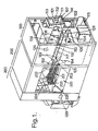
- Fig. 1 shows a reverse vending apparatus where certain parts, inter alia, the front panel, have been removed in order to make some details more visible.
- the reverse vending apparatus consists of three main sections 100, 200 and 300.
- the main section 100 has an insertion opening 101, wherein containers, such as empty bottles of glass or plastic, optionally containers in the form of empty cans made of glass, plastic, metal or wood, can be placed on a V-shaped conveyor 102 consisting of an inclined conveyor belt 103 which is driven over a pair of rollers 104, 105 by means of a motor 106.
- the V-shaped conveyor also has an inclined, stationarily positioned sliding surface 107.
- the sliding surface may be equipped with a metal detector 108.
- a video camera 109 is placed such that it looks down towards the conveyor 102, for example, through a window or opening 110.
- the reverse vending apparatus will be especially useful in connection with the payment of return deposits, where a user will be able to insert containers onto the conveyor 102 and request a receipt for the accepted containers by pushing a control button 111.
- a receipt will then be supplied via an opening in a printer 112, so that the receipt can be exchanged for cash.
- the printer can be replaced by a coin dispenser.
- a device is conceivable wherein the apparatus user can selectively determine that the return deposits are to be donated to a charity, e.g., the Red Cross, SOS-Kinderdorf, the Salvation Army or the like.
- At least one display 113 it will be advantageous to use at least one display 113.
- a further display 114 can be provided, e.g., a further display 114.
- Both the displays can, e.g., be of the LCD type.
- a return opening 115 which communicates with the section 200 where sorting out can take place.
- the section 100 may further contain a loudspeaker 116 for signalling messages to the user of the reverse vending apparatus or to give audio signals which summon the attention of the user or the maintenance staff.
- a loudspeaker 116 for signalling messages to the user of the reverse vending apparatus or to give audio signals which summon the attention of the user or the maintenance staff.
- a load cell 117 arranged on the stationary part 107 of the conveyor 102.
- a load cell 117 there will also be other facilities for detecting whether a container that is inserted contains a substance, e.g., liquid, or not.
- a memory card device which makes it possible to exchange information with a computer in the apparatus by using special data cards.
- a display 120 for maintenance and repair staff can also be provided in the apparatus, preferably in section 100, in connection with a suitable computer 121.
- the reverse vending apparatus may also be connected to a modem, so that data can be tele-transmitted to and from the apparatus, e.g., in connection with fault reports or fault repair of simple faults.
- the modem is indicated by means of the reference numeral 122. Furthermore, it is possible to provide a point-of-sale (POS) computer 123 in the shop or the business location where the reverse vending apparatus is located. A computer of this kind might be useful for statistical purposes, communication with check-outs in a shop or supermarket, or to ensure that a receipt that is cashed in at a check-out cannot be cashed in again.
- POS point-of-sale
- the said functional members 113, 114, 111, 116-123 are, as shown in Fig. 2, connected to a motherboard 124 which contains a microprocessor, a memory and input and output units for data to and from the motherboard.
- the motherboard and thus also the said members 113, 114, 111, plus 116-123 are supplied with working voltage, e.g., +24V DC via the motherboard.
- the motherboard 124 communicates with a video capture card 125, a motor control card 126 and a motor auxiliary card 127 via an expansion bus 128.
- the video capture card 125 receives input from the video camera 109.
- the video capture card may contain a digital signal processor, a video frame storage device, and means for input and output of data.
- the video capture card may be equipped with a lighting means 129 so as to be able to provide the right lighting in connection with the detection of the shape of a container.
- the video capture card 125 operates as a video picture analyser. Consequently, the video capture card 125 may have many functions, according to requirement in respect of what is to be analysed in the video image of the container which is captured by the video camera 109.
- the video capture card has an insertion analyser 130 which analyses the video image whilst the container is conveyed, in lying position and with its axis parallel to the direction of conveyance, past the video camera. Consequently, this insertion analyser may contain a calculator component and a control component.
- the video camera 109 Before a container, e.g., a bottle, is put on the conveyor 102, the video camera 109 will show a video image essentially as shown in Fig. 3a.
- Fig. 3b it is shown how an attempt is made to insert a bottle mouth (top portion or neck of bottle) first.
- the calculator component in the insertion analyser 130 will thus first determine that the container in this case has been inserted incorrectly.
- the control component which is included in the analyser 130 will cause the container B to be fed back to the insertion portion of the reverse vending apparatus at the start of the conveyor 102.
- a signal will be given to the apparatus user that he should turn the container so that the bottom of the container B is inserted first on reinsertion.
- the video image will appear approximately as shown in Fig. 3c.
- the bottom of the container, in this case a bottle is indicated by means of the reference B2.
- FIG. 3a thus merely serves as an example to elucidate essential features of the use of a video camera to obtain a number of characteristic features of a container which is fed past the video camera 109.
- the calculator component would have calculated that the container was moving into the video image with the container bottom B2 first, and thus cause the container to be conveyed further to a discharge station in either section 200 or section 300.
- Fig. 3d it is shown how the outer contour of the bottle is visible.
- the position which the container 3 has in the range of vision of the video camera is determined on the basis of the container's position in the video image. This can take place with the aid of a position detector 131 which constitutes a part of the video capture card. With the aid a position detector of this kind it is possible to establish where the container is relative of to the length of the detection zone, at the same time as the position detector 131 indicates separation between containers that are inserted.
- the video capture card 125 preferably includes a container shape calculation circuit 132.
- the circuit 132 is capable of calculating a characteristic expression of the shape of the container, such as the container's contour, surface area, cross-section or the like.
- the video camera 109 may expediently be a black and white camera, but use of a colour video camera is also conceivable. If a colour video camera is used, a colour determination circuit 133 which is included in the video capture card 125 can be put to use.
- the video capture card 125 may also contain a bar code reader 134 which is adapted to scan continuously a field of the video image in order to look for and register a bar code located on the container, indicated by means of the reference numeral 135 in Fig. 3e.
- the bar code will in a number of cases give indirect information with regard to, e.g., the colour of the bottle, so that use of a black and white camera is sufficient.
- the video capture card may also include, in connection with the bar code reader 134, a circuit which causes the container to be conveyed back to the insertion portion 115 of the reverse vending apparatus if the microprocessor 124 does not accept the container because of the bar code reading made by the bar code reader 134.
- a small gap will occur between the conveyors 102 and 201, i.e., between respective rotatory rollers 105 and 202.
- Conventional bar code sensors 162, 163 and 164 may be located in the gap, and where each will cover an area of detection on the container equal to about 120°.
- the reference numeral 138' in Fig. 3e denotes typical and possibly longitudinal markings in the video image of a container, which indicate that the bottle wholly or partly contains liquid. In the illustrated case a small residue is present in the bottle. This can be registered by a subcircuit 138. Owing to the varying weight of the bottle, it will be crucial to supplement the video image analysis with a weighing by using the load cell 117, and also a capacitance meter 137.
- Figs. 3f and 3g show the container, here in the form of a bottle, on its way out of the detection area.
- the video capture card 125 with its subcircuits 130, 131, 132, 133, 134, 136 and 138, communicates with the motherboard 124 via the expansion bus 128, and the motor control card 126 is thus actuated via the motherboard 124.
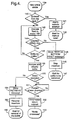
- Fig. 4 shows a flow chart in connection with some of the detection functions attended to by the video capture card.
- block 139 there appears a new article in the form of a container B, as shown in Fig. 3b or Fig. 3c.
- block 140 will decide whether this happens or not.
- block 140 will emit an affirmative signal, which will set off an alarm at block 141 as an indication of attempted swindle.
- the reverse vending apparatus will stop its function as shown in block 142, as in this case there must be a pause for the manual resetting of the reverse vending apparatus. If no attempt at swindle is made, so that the container, bottle or, e.g., can, is thus fed into the detection zone from right to left as shown in Fig. 3, the block 140 will emit a negative signal, which initiates at block 143 operation of insertion motor 106.
- the insertion analyser 130 will decide whether the container is inserted bottom first. If this is not the case, a negative signal will be discharged from the block 144, which at block 145 initiates a message to the apparatus user to insert the container, in this example a bottle, "bottle bottom first".
- a message of this kind can, e.g., be shown on the display 113. Subsequently the insertion is stopped in that the motor 106 is stopped, as indicated by block 146. There is then a short pause whilst the apparatus user retrieves the container, that is, e.g., the bottle or can, for reinsertion, as is indicated by block 147. If it is established at block 144 that the container is inserted bottom first, an affirmative signal is emitted. Subsequently it is established at block 148 whether the container's top, in this case the bottle top portion, is visible or not. If the container top is not visible, as in Fig.
- a negative signal is emitted from the block 148, which via block 143 causes the insertion motor 106 to be run until the container top is visible.
- the container in this case is analysed and classified, e.g., by using one or more of the circuits 130-134 and 136, 138. If the container, e.g., a bottle, is deemed to be accepted, as indicated by block 150, an affirmative signal is emitted.
- the digital signal processor in the video capture card 125 asks whether the container has passed the detection area or the shape chamber. If the container has come as far in the video image as shown in Fig. 3g, the position detector 131 will emit an affirmative signal, which, as indicated at block 152, signals that the return deposit value is to be accumulated in the motherboard 124. Subsequently a "bottle processed" signal 153 is emitted.
- the section 200 of the reverse vending apparatus will now be described in more detail with reference to Figs. 1, 2 and 5-9.
- This section of the apparatus is designed for sorting containers which are inserted and which pass through the section 100.
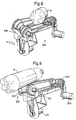
- Fig 1 there is shown downstream of the conveyor 102 a further conveyor 201 which has a first rotatory roller unit 202 and a second rotatory roller unit 203.
- the first roller unit 202 has a stationary axis of rotation 204.
- the roller unit 202 is mounted in a fixed bracket 205.
- a first motor 206 is operatively connected to the roller unit 202 via a transmission 207. The motor 206 thereby causes rotation of the roller unit 202.
- rotation of the second roller unit 203 is also effected in that a plurality of adjacently disposed elastic belts or bands 208, 209, 210 and 211 are provided, which run in grooves made for this purpose, such as the grooves 212, 213, 214 and 215 on the roller unit 203.
- the belts or bands 208-211 may, e.g., have a circular, rectangular, triangular or other polygonal cross-section.
- the conveyor 201 has a supporting frame 217 to which is secured a motor bracket 218 in which a motor 219 is suspended.
- the holder 216 is tiltable.
- the motor 219 will via a connection 220 be made capable of steering the tiltable holder 216 in one direction or another in a plane transverse to the conveyor 201 from a centre position (as shown in Fig. 6) where the axis of rotation of the second roller unit is parallel to the axis of rotation of the first roller unit.
- the axis of rotation of the second roller unit is in Fig. 6 denoted by the reference numeral 221.
- the detector unit as represented by the motherboard 124 and the video capture card 125, contains a control circuit 156, advantageously provided on the motherboard 124, which control circuit 156, on the basis of data linked to the detectable container with a view to whether the container is to be sorted out in the station 200 or conveyed further, either actuates the second motor 219 to turn in order to tilt the second roller unit 203 holder 216 a certain angle ( ⁇ 1; ⁇ 2) to one side or the other, as indicated in Figs. 7 and 8 in order to cause a container of the type in question, e.g., B, which is lying on the conveyor 201 to be tipped to one side or the other to a first exit 222 as indicated in Figs.
- a container of the type in question e.g., B, which is lying on the conveyor 201 to be tipped to one side or the other to a first exit 222 as indicated in Figs.
- a second exit 223 as shown in Fig. 1 and indicated in Fig. 8.
- the container e.g., a bottle or a can
- containers are discharged to the first exit 222, these will be fed via a chute to the exit 115 in the first section 100.
- Containers which are discharged to the second exit 223 may, e.g., be metal cans such as aluminium cans which are to be carried further for compaction in any case and do not need to be fed to the section 300.
- the exit 223 may conceivably contain a controllable flap 228 driven by a motor or actuator 229.
- the flap 228 will thus in reality serve as an extra container sorter at the exit 223.
- Corresponding flaps may optionally be provided at the exit 222 (not shown in Fig. 1).
- the roller units 202 and 203 preferably have a double-cone configuration, a so-called "diabolo" shape.
- the motors 206 and 219 are preferably stepping motors.
- Containers of metal which contain metal e.g., steel, metal cans which wholly or partly contain or consist of steel or containers which contain foreign bodies will normally be sorted out to the first exit 222 for return to the reverse vending apparatus user, as such containers normally will not be accepted because they can neither be compacted, further treated or recycled. These must therefore be dealt with in another way.
- metal e.g., steel
- metal cans which wholly or partly contain or consist of steel or containers which contain foreign bodies will normally be sorted out to the first exit 222 for return to the reverse vending apparatus user, as such containers normally will not be accepted because they can neither be compacted, further treated or recycled.
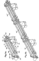
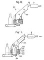
- a bottle raiser 310 At the downstream end of the conveyor 201, there is provided according to the invention, a bottle raiser 310, with a view to conducting transported bottles B which arrive bottom B2 first from a lying position, as indicated to the right in Figs. 10 and 11, to a vertical or standing position as shown clearly in Fig. 11.
- the bottle raiser comprises a curved guide duct or shaft 302 which provides a guide or slide for the bottle B and a shock absorbing rest 303.
- the guide duct 302 may be of different lengths and may be constructed to guide bottles across of distance of some meters, e.g., from one floor to a floor below, as indicated in Fig. 23.
- the guide duct may have, e.g., an upright portion 302'.
- the guide duct 302' may run into a curved portion 302" for transferring the bottles in lying position to the guide duct 302'.
- the bottle raiser may also conceivably be used for bottles which are discharged from a reverse vending apparatus 400 in standing position. The bottle will thus arrive in standing position with it bottom against the rest 303.
- the rest 303 may be positioned horizontally.
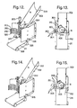
- a bottle stabiliser indicated by means of the reference numeral 304 is operated by a stepping motor 305 (for the sake of simplicity only shown in Fig. 12).
- the bottle stabiliser 304 is a rotatable unit having at least one vertical wing 306 which is secured to a vertical spindle 307.
- the wing shown in Fig 13 will be in contact freedom with the bottle B as a function of data calculated by the motherboard 124 of the detector section relating to the bottle, e.g., diameter, height and weight, whereby the bottle B is capable of being guided freely down towards the rest 303. Then the wing 306, on control from the motherboard and thus via the motor control card 126, will be brought into a second position as shown in Fig. 15 in contact against a portion of the bottle and push the bottle B towards a back wall 308 in said duct or shaft 302.
- the bottle stabiliser 304 is made so that it also functions as a bottle ejector.
- the bottle stabiliser can, for example, be equipped with additional wings, e.g., wings 309 and 310, the motor 305 on stabilisation as shown in Figs. 14 and 15 turning, when seen from above, anti-clockwise, whilst the unit 304, as shown in Fig. 17, turns clockwise thereby causing the wing 310 to push the bottle B onto a further conveyor 311, preferably with the aid of a guide wall 312.
- additional wings e.g., wings 309 and 310
- the motor 305 on stabilisation as shown in Figs. 14 and 15 turning, when seen from above, anti-clockwise, whilst the unit 304, as shown in Fig. 17, turns clockwise thereby causing the wing 310 to push the bottle B onto a further conveyor 311, preferably with the aid of a guide wall 312.
- the combined bottle stabiliser and bottle ejector 304 is preferably equipped with three vertical wings. However, it will be understood that it is fully possible to use a smaller number of wings or perhaps a larger number of wings if the bottle dimensions are small or the spindle 307 is some distance from the side of the guide duct or shaft 302.
- At least the lower portion of the wings 306, 309 and 310 are made having a plurality of fingers, such as the fingers 313, 314, 315, 316, for the wing 306 and the fingers 317, 318, 319 and 320 for the wing 309, as shown in Fig. 12.
- the fingers on the wing 310 are poorly visible in Fig. 20, but will have a design corresponding to those on the wings 306 and 309.
- the back wall 308 is also made having fingers 321, 322, 323, 324 and 325, so that the finger portions on the wings 306, 309 and 310 can pass between the mutual space between the fingers 321-325 of the back wall.
- the respective wings 306, 309 and 310 in the rotating unit which constitutes both the bottle stabiliser and the bottle ejector are slightly curved. This curve is desirable in order to ensure a controlled stabilisation and ejection.
- the wings 306, 309 and 310 have preferably the same angular separation.
- a new bottle B comes into place on the horizontal rest 303 and is ready for stabilisation with the aid of the wing 310 which has just ejected the bottle.
- it will always be the wing which has ejected the previous bottle which will have a stabilising effect on the next bottle.
- an efficient operation is achieved by the combined bottle stabiliser and bottle ejector 304.
- an arrival sensor 326 In order to register that a bottle comes into place on the rest 303, there may be provided at a lower portion of the guide, an arrival sensor 326 which views the space at the bottom of the guide or shaft 302.
- the conveyor 311 is driven by a motor 327, which for the sake of simplicity is indicated on only Fig. 12.
- the conveyor 311 will, with the aid of the motor 327, cause the ejected bottles to be transported further.
- the conveyor 311 may either convey the bottles in the same direction as they were conveyed through the sections 100 and 200, or provide transport in a transverse direction with the aid of a transversely positioned conveyor 335, as shown in Fig. 22.
- the guide wall 321 should be extended and made having a curve as is shown by means of the reference numeral 336.
- the motor 327 may either be a motor designed for continuous operation or a typical stepping motor.
- the conveyor 311 is operated in a known way per se over respective end rollers 328 and 329.
- the position sensor 327 in connection with the bottle raiser 301 it may also be expedient to provide the bracket 218 with a position sensor 225 which views an indicator 226 which is fixedly mounted on the tiltable holder 216. In this way a centre position for the holder 216 can always be accurately registered.
- a position sensor 227 on the actual frame of the conveyor 201 close to the position of the holder 216, so that when the sensor 227 registers that a container bottom has reached the position of the sensor 227 and is to be thrown out to one side or the other as shown in Figs. 7 and 8, respectively, the motor 206 is made to stop, whilst the motor 219 operates to tilt the holder 216 to one side or the other as shown in Figs. 7 and 8.
- a network distributor card 159 which is connected to a 12-channel serial bus which communicates with the motherboard 124, and where the bus is also connected to an in/out channel card 161 which on detection of, e.g., a stoppage in the discharge from the conveyor 311, as a result of a stoppage signal from a detector 330, emits a external alarm 331.
- the stoppage may be attributable to the fact that a collection table 332, which follows immediately after the conveyor 311, has become full.
Priority Applications (3)
| Application Number | Priority Date | Filing Date | Title |
|---|---|---|---|
| EP20040076029 EP1467328B1 (fr) | 1996-07-12 | 1997-07-10 | Méthode et machine de déconsignation pour le traitement de conteneurs vides de boissons |
| DK04076025T DK1441312T3 (da) | 1996-07-12 | 1997-07-10 | Indretning og fremgangsmåde til at rejse, stabilisere og bevæge en flaske videre |
| EP20040076025 EP1441312B1 (fr) | 1996-07-12 | 1997-07-10 | Dispositif et méthode pour soulever, stabiliser et faire avancer une bouteille |
Applications Claiming Priority (3)
| Application Number | Priority Date | Filing Date | Title |
|---|---|---|---|
| NO962949 | 1996-07-12 | ||
| NO962949A NO306661B1 (no) | 1996-07-12 | 1996-07-12 | FremgangsmÕte og anordning for detektering av væskebeholdere |
| EP97932037A EP0910485B1 (fr) | 1996-07-12 | 1997-07-10 | Procede et dispositif pour detecter des recipients de liquides |
Related Parent Applications (2)
| Application Number | Title | Priority Date | Filing Date |
|---|---|---|---|
| EP97932037A Division EP0910485B1 (fr) | 1996-07-12 | 1997-07-10 | Procede et dispositif pour detecter des recipients de liquides |
| EP97932037A Division-Into EP0910485B1 (fr) | 1996-07-12 | 1997-07-10 | Procede et dispositif pour detecter des recipients de liquides |
Related Child Applications (2)
| Application Number | Title | Priority Date | Filing Date |
|---|---|---|---|
| EP20040076025 Division EP1441312B1 (fr) | 1996-07-12 | 1997-07-10 | Dispositif et méthode pour soulever, stabiliser et faire avancer une bouteille |
| EP20040076029 Division EP1467328B1 (fr) | 1996-07-12 | 1997-07-10 | Méthode et machine de déconsignation pour le traitement de conteneurs vides de boissons |
Publications (2)
| Publication Number | Publication Date |
|---|---|
| EP1107194A1 true EP1107194A1 (fr) | 2001-06-13 |
| EP1107194B1 EP1107194B1 (fr) | 2004-09-22 |
Family
ID=19899614
Family Applications (4)
| Application Number | Title | Priority Date | Filing Date |
|---|---|---|---|
| EP97932037A Expired - Lifetime EP0910485B1 (fr) | 1996-07-12 | 1997-07-10 | Procede et dispositif pour detecter des recipients de liquides |
| EP20040076029 Revoked EP1467328B1 (fr) | 1996-07-12 | 1997-07-10 | Méthode et machine de déconsignation pour le traitement de conteneurs vides de boissons |
| EP20040076025 Revoked EP1441312B1 (fr) | 1996-07-12 | 1997-07-10 | Dispositif et méthode pour soulever, stabiliser et faire avancer une bouteille |
| EP20000124816 Expired - Lifetime EP1107194B1 (fr) | 1996-07-12 | 1997-07-10 | Procédé et dispositif pour la détection du sens de déplacement de conteneurs de liquides |
Family Applications Before (3)
| Application Number | Title | Priority Date | Filing Date |
|---|---|---|---|
| EP97932037A Expired - Lifetime EP0910485B1 (fr) | 1996-07-12 | 1997-07-10 | Procede et dispositif pour detecter des recipients de liquides |
| EP20040076029 Revoked EP1467328B1 (fr) | 1996-07-12 | 1997-07-10 | Méthode et machine de déconsignation pour le traitement de conteneurs vides de boissons |
| EP20040076025 Revoked EP1441312B1 (fr) | 1996-07-12 | 1997-07-10 | Dispositif et méthode pour soulever, stabiliser et faire avancer une bouteille |
Country Status (9)
| Country | Link |
|---|---|
| US (1) | US6137900A (fr) |
| EP (4) | EP0910485B1 (fr) |
| JP (1) | JP3989556B2 (fr) |
| AT (4) | ATE304728T1 (fr) |
| AU (1) | AU3559597A (fr) |
| DE (6) | DE69706856T2 (fr) |
| DK (4) | DK1467328T3 (fr) |
| NO (1) | NO306661B1 (fr) |
| WO (1) | WO1998002256A1 (fr) |
Families Citing this family (38)
| Publication number | Priority date | Publication date | Assignee | Title |
|---|---|---|---|---|
| AT404717B (de) * | 1997-04-17 | 1999-02-25 | Knapp Holding Gmbh | Verfahren zur kontrolle von zu einem kommissionierauftrag gehörenden stückgütern und vorrichtung zur durchführung des verfahrens |
| US7167892B2 (en) * | 1998-03-19 | 2007-01-23 | Isochron, Inc. | System, method and apparatus for vending machine wireless audit and cashless transaction transport |
| US6186308B1 (en) * | 1999-04-21 | 2001-02-13 | Can & Bottle Systems, Inc. | Reverse vending machine |
| US6675947B2 (en) | 2001-03-30 | 2004-01-13 | Can & Bottle Systems, Inc. | Recycling machine with container compacting system |
| DE10138438A1 (de) * | 2001-03-30 | 2002-10-10 | Klaus Rudolph | Vorrichtung zum Sortieren und/oder Sammeln von Materialien und ein Verfahren zum Betreiben einer derartigen Anlage |
| NO20020580L (no) * | 2002-02-05 | 2003-08-06 | Zopa As | Transportenhet for å transportere et produkt langs en bane og anordning forå lade en energilagringsenhet i transportenheten |
| DE10209504A1 (de) * | 2002-02-22 | 2003-09-18 | Rur Elektro Gmbh | Verfahren zum Sammeln von Pfandverpackungen, Preßvorrichtungen und Sammelbehältnis |
| DE10209864A1 (de) * | 2002-03-06 | 2003-09-25 | Knapp Logistik Automation | Verfahren und Anordnung zum Erkennen und Steuern von mit einem Code versehenen Stückgütern |
| NO316956B1 (no) * | 2002-06-26 | 2004-07-05 | Tomra Systems Asa | Anordning for gjenkjennelse av beholdere |
| NO20023090L (no) * | 2002-06-26 | 2003-12-29 | Tomra Systems Asa | Anordning for gjenkjennelse av beholdere |
| WO2005069233A1 (fr) * | 2004-01-16 | 2005-07-28 | Tomra Systems Asa | Procede et dispositif pour observer des caracteristiques d'un objet |
| US7564600B2 (en) * | 2004-03-05 | 2009-07-21 | Kabushiki Kaisha Toshiba | Image reading apparatus |
| US7490773B2 (en) * | 2004-12-03 | 2009-02-17 | Mcvicker Henry J | Apparatus and method for obtaining an image of an arcuate surface |
| PL1842169T3 (pl) * | 2005-01-25 | 2019-07-31 | Tomra Systems Asa | Środki w zwrotnym automacie sprzedającym do odbierania, przenoszenia, sortowania i przechowywania przedmiotów lub obiektów zwrotnych |
| DE102005006562A1 (de) * | 2005-02-11 | 2006-08-24 | Hans-Hermann Trautwein Sb-Technik Gmbh | Rücknahmegerät für Leergutgebinde |
| US8560459B2 (en) | 2005-11-17 | 2013-10-15 | Casella Waste Systems, Inc. | Methods and facilities for a municipal solid waste management system |
| US7780085B2 (en) * | 2005-12-09 | 2010-08-24 | Larue John D | Round surface scanner |
| NO323842B1 (no) * | 2006-02-28 | 2007-07-09 | Tomra Systems Asa | Fremgangsmate og anordning for overstyring av returautomat |
| DE102006016596B3 (de) * | 2006-04-06 | 2007-08-23 | Wincor Nixdorf International Gmbh | Transporteinheit in einem Rücknahmesystem für Leergut |
| DE102006041888B3 (de) * | 2006-08-23 | 2008-03-27 | Wincor Nixdorf International Gmbh | Aufstellvorrichtung für Leergutbehälter |
| DE202007001682U1 (de) * | 2007-02-06 | 2008-03-20 | Wincor Nixdorf International Gmbh | Leergutrücknahmeautomat |
| DE102007057569B3 (de) * | 2007-10-20 | 2009-05-20 | Wincor Nixdorf International Gmbh | Transporteinheit für Leergut |
| DE102008006382A1 (de) | 2008-01-29 | 2009-07-30 | Wincor Nixdorf International Gmbh | Erkennung von Material und Füllzustand von Leergutbehältern |
| DE102008038003A1 (de) | 2008-08-16 | 2010-02-18 | Wincor Nixdorf International Gmbh | Vorrichtung und Verfahren zum Aufrichten und Sortieren eines Leergutbehälters in Leergutrücknahmeautomaten |
| US8284305B2 (en) * | 2008-11-26 | 2012-10-09 | Parata Systems, Llc | System and method for acquiring images |
| IT1398360B1 (it) * | 2009-01-21 | 2013-02-22 | Falanga | Sistema di differenzazione di imballaggi caratterizzati per dispositivo di riconoscimento caratterizzato |
| DE102010006116A1 (de) | 2010-01-29 | 2011-08-04 | Hans-Hermann Trautwein SB-Technik GmbH, 73760 | Verfahren und Vorrichtung zur Identifizierung der Kontur von Körpern, vorzugsweise von zumindest nahezu achssymmetrischen Flüssigkeitsbehältern |
| DK2538394T3 (da) * | 2011-06-24 | 2022-02-14 | Tomra Systems Asa | Fremgangsmåde og apparat til at opdage svindelforsøg i returautomater |
| US9890914B2 (en) | 2013-01-18 | 2018-02-13 | Raves Equipment Company | Lighting assembly |
| US9002742B2 (en) | 2013-03-14 | 2015-04-07 | Elisah DUMAS | Computer implemented method for a recycling company to increase recycling demand |
| DK2851875T3 (da) * | 2013-09-19 | 2022-03-14 | Wincor Nixdorf Int Gmbh | Returautomat til returemballage |
| EP3208782B1 (fr) | 2016-02-22 | 2022-10-19 | Wincor Nixdorf International GmbH | Dispositif de reprise pour bouteilles consignees |
| WO2018085180A1 (fr) | 2016-11-07 | 2018-05-11 | Wal-Mart Stores, Inc. | Appareil et procédé pour exécuter une commande avec des récipients usagés |
| US10582790B2 (en) * | 2017-02-23 | 2020-03-10 | Panasonic Intellectual Property Management Co., Ltd. | Bottle storage |
| EP3579203B1 (fr) * | 2018-06-05 | 2021-08-11 | Wincor Nixdorf International GmbH | Élément de guidage de produits vides, dispositif de manipulation de produits vides et système de récupération de produits vides |
| CN109165568A (zh) * | 2018-08-02 | 2019-01-08 | 小黄狗环保科技有限公司 | 一种基于变形塑料瓶形状特征通用的识别方法 |
| EP3654303A1 (fr) * | 2018-11-15 | 2020-05-20 | Tomra Systems ASA | Distributeur automatique inverse |
| KR102214151B1 (ko) * | 2019-10-28 | 2021-02-10 | 수퍼빈 주식회사 | 재활용 용기 분류 및 압축 장치 |
Citations (12)
| Publication number | Priority date | Publication date | Assignee | Title |
|---|---|---|---|---|
| US4256957A (en) | 1977-08-11 | 1981-03-17 | T I Fords Limited | Bottle inspection apparatus |
| GB2121579A (en) * | 1982-03-31 | 1983-12-21 | Coin Controls | Coin validating |
| GB2152208A (en) * | 1983-12-23 | 1985-07-31 | Sigma Enterprises Inc | Optoelectronic coin entry sensing system for coin operated machines |
| US4625107A (en) | 1983-02-24 | 1986-11-25 | A/S Tomra Systems | Method for contour recognition of totally or partly transparent objects, e.g., bottles |
| EP0174549B1 (fr) | 1984-08-29 | 1989-11-15 | Halton Oy | Dispositif pour identifier et enregistrer des bouteilles et/ou des caisses de bouteilles |
| US5007096A (en) | 1987-02-18 | 1991-04-09 | Hajime Industries Ltd. | Object inspection apparatus |
| US5150307A (en) | 1990-10-15 | 1992-09-22 | Automation Industrial Control, Inc. | Computer-controlled system and method for sorting plastic items |
| US5355987A (en) | 1992-03-16 | 1994-10-18 | Environmental Products Corporation | Single station reverse vending machine |
| US5443164A (en) | 1993-08-10 | 1995-08-22 | Simco/Ramic Corporation | Plastic container sorting system and method |
| EP0696781A2 (fr) * | 1994-08-10 | 1996-02-14 | Walter Grässle GmbH | Dispositif et méthode pour la reprise d'articles creux |
| JPH08168726A (ja) | 1994-12-16 | 1996-07-02 | Tekuniile:Kk | 空容器の自動選別収集装置 |
| US5675516A (en) | 1995-09-27 | 1997-10-07 | Inex Vision Systems, Inc. | System and method for determining pushup of a molded glass container |
Family Cites Families (10)
| Publication number | Priority date | Publication date | Assignee | Title |
|---|---|---|---|---|
| NO135609C (fr) * | 1975-06-03 | 1977-05-11 | Tore Planke | |
| US3998320A (en) | 1976-02-23 | 1976-12-21 | Owens-Illinois, Inc. | Plastic bottle escapement device and method |
| EP0034088B1 (fr) * | 1980-02-12 | 1986-04-09 | Supermarket Systems | Appareil d'identification d'objets tels que des bouteilles |
| NO151313C (no) * | 1982-11-01 | 1985-03-27 | Tomra Systems As | Fremgangsmaate og anordning for identifisering og sortering av metallbokser. |
| FI82992C (fi) * | 1988-12-02 | 1992-10-20 | Halton Oy | Foerfarande vid behandling av returflaskor och behandlingsanordning foerreturflaskor |
| FI903419A (fi) * | 1990-07-06 | 1992-01-07 | Halton Oy | Foerfarande och anordning vid sortering av returfoerpackningar av returflaskor, burkar m.m. |
| DE4214250A1 (de) * | 1992-04-30 | 1993-11-04 | Trautwein Sb Technik Gmbh | Leerflaschenruecknahmegeraet |
| US5600303A (en) * | 1993-01-15 | 1997-02-04 | Technology International Incorporated | Detection of concealed explosives and contraband |
| US5370216A (en) | 1993-03-05 | 1994-12-06 | Shibuya Kogyo Co., Ltd. | Apparatus for aligning vessels |
| GB9323709D0 (en) | 1993-11-15 | 1994-01-05 | Ncr Int Inc | Depository apparatus for envelopes and single sheets |
-
1996
- 1996-07-12 NO NO962949A patent/NO306661B1/no not_active IP Right Cessation
-
1997
- 1997-07-10 AT AT04076029T patent/ATE304728T1/de not_active IP Right Cessation
- 1997-07-10 EP EP97932037A patent/EP0910485B1/fr not_active Expired - Lifetime
- 1997-07-10 WO PCT/NO1997/000179 patent/WO1998002256A1/fr active IP Right Grant
- 1997-07-10 DE DE1997606856 patent/DE69706856T2/de not_active Expired - Lifetime
- 1997-07-10 DE DE2004076025 patent/DE04076025T1/de active Pending
- 1997-07-10 DE DE2004076029 patent/DE04076029T1/de active Pending
- 1997-07-10 DK DK04076029T patent/DK1467328T3/da active
- 1997-07-10 AU AU35595/97A patent/AU3559597A/en not_active Abandoned
- 1997-07-10 JP JP50589198A patent/JP3989556B2/ja not_active Expired - Fee Related
- 1997-07-10 EP EP20040076029 patent/EP1467328B1/fr not_active Revoked
- 1997-07-10 DE DE1997634220 patent/DE69734220T2/de not_active Expired - Lifetime
- 1997-07-10 AT AT97932037T patent/ATE205756T1/de active
- 1997-07-10 DE DE1997634792 patent/DE69734792T2/de not_active Expired - Lifetime
- 1997-07-10 DE DE1997630876 patent/DE69730876T2/de not_active Expired - Lifetime
- 1997-07-10 AT AT04076025T patent/ATE311640T1/de active
- 1997-07-10 DK DK00124816T patent/DK1107194T3/da active
- 1997-07-10 DK DK04076025T patent/DK1441312T3/da active
- 1997-07-10 US US08/973,152 patent/US6137900A/en not_active Expired - Lifetime
- 1997-07-10 DK DK97932037T patent/DK0910485T3/da active
- 1997-07-10 AT AT00124816T patent/ATE277388T1/de active
- 1997-07-10 EP EP20040076025 patent/EP1441312B1/fr not_active Revoked
- 1997-07-10 EP EP20000124816 patent/EP1107194B1/fr not_active Expired - Lifetime
Patent Citations (12)
| Publication number | Priority date | Publication date | Assignee | Title |
|---|---|---|---|---|
| US4256957A (en) | 1977-08-11 | 1981-03-17 | T I Fords Limited | Bottle inspection apparatus |
| GB2121579A (en) * | 1982-03-31 | 1983-12-21 | Coin Controls | Coin validating |
| US4625107A (en) | 1983-02-24 | 1986-11-25 | A/S Tomra Systems | Method for contour recognition of totally or partly transparent objects, e.g., bottles |
| GB2152208A (en) * | 1983-12-23 | 1985-07-31 | Sigma Enterprises Inc | Optoelectronic coin entry sensing system for coin operated machines |
| EP0174549B1 (fr) | 1984-08-29 | 1989-11-15 | Halton Oy | Dispositif pour identifier et enregistrer des bouteilles et/ou des caisses de bouteilles |
| US5007096A (en) | 1987-02-18 | 1991-04-09 | Hajime Industries Ltd. | Object inspection apparatus |
| US5150307A (en) | 1990-10-15 | 1992-09-22 | Automation Industrial Control, Inc. | Computer-controlled system and method for sorting plastic items |
| US5355987A (en) | 1992-03-16 | 1994-10-18 | Environmental Products Corporation | Single station reverse vending machine |
| US5443164A (en) | 1993-08-10 | 1995-08-22 | Simco/Ramic Corporation | Plastic container sorting system and method |
| EP0696781A2 (fr) * | 1994-08-10 | 1996-02-14 | Walter Grässle GmbH | Dispositif et méthode pour la reprise d'articles creux |
| JPH08168726A (ja) | 1994-12-16 | 1996-07-02 | Tekuniile:Kk | 空容器の自動選別収集装置 |
| US5675516A (en) | 1995-09-27 | 1997-10-07 | Inex Vision Systems, Inc. | System and method for determining pushup of a molded glass container |
Non-Patent Citations (1)
| Title |
|---|
| PATENT ABSTRACTS OF JAPAN vol. 199, no. 611 29 November 1996 (1996-11-29) |
Also Published As
| Publication number | Publication date |
|---|---|
| DK1107194T3 (da) | 2005-01-24 |
| ATE304728T1 (de) | 2005-09-15 |
| ATE311640T1 (de) | 2005-12-15 |
| DE04076025T1 (de) | 2005-08-18 |
| AU3559597A (en) | 1998-02-09 |
| DE69730876T2 (de) | 2005-11-10 |
| DE69734220D1 (de) | 2005-10-20 |
| EP0910485A1 (fr) | 1999-04-28 |
| EP1467328A1 (fr) | 2004-10-13 |
| US6137900A (en) | 2000-10-24 |
| DE69706856T2 (de) | 2002-04-11 |
| EP1441312B1 (fr) | 2005-11-30 |
| EP1107194B1 (fr) | 2004-09-22 |
| DE69734792T2 (de) | 2006-08-03 |
| DE69706856D1 (de) | 2001-10-25 |
| NO962949D0 (no) | 1996-07-12 |
| DK1467328T3 (da) | 2006-01-09 |
| JP2000514709A (ja) | 2000-11-07 |
| DE69734792D1 (de) | 2006-01-05 |
| EP1441312A1 (fr) | 2004-07-28 |
| DE04076029T1 (de) | 2005-08-18 |
| ATE205756T1 (de) | 2001-10-15 |
| DE69734220T2 (de) | 2006-07-06 |
| EP1467328B1 (fr) | 2005-09-14 |
| NO962949L (no) | 1998-01-13 |
| EP0910485B1 (fr) | 2001-09-19 |
| NO306661B1 (no) | 1999-12-06 |
| DK0910485T3 (da) | 2002-01-28 |
| DE69730876D1 (de) | 2004-10-28 |
| ATE277388T1 (de) | 2004-10-15 |
| DK1441312T3 (da) | 2006-03-27 |
| JP3989556B2 (ja) | 2007-10-10 |
| WO1998002256A1 (fr) | 1998-01-22 |
Similar Documents
| Publication | Publication Date | Title |
|---|---|---|
| EP1107194B1 (fr) | Procédé et dispositif pour la détection du sens de déplacement de conteneurs de liquides | |
| US5934440A (en) | Conveyor device for inspecting containers and transporting them to selected destinations | |
| US6012588A (en) | Device for a conveyor means | |
| US20120173014A1 (en) | Reverse Vending Machine | |
| US7754990B2 (en) | Means in a reverse vending machine (RVM) for receiving, handling, sorting and storing returnable items or objects | |
| US7416142B2 (en) | Methods and apparatus for processing recyclable containers | |
| US7317962B2 (en) | Methods and apparatus for managing information related to recyclable containers | |
| US6186308B1 (en) | Reverse vending machine | |
| US7110590B2 (en) | Method and return vending machine device for handling empty beverage containers | |
| CN108537995A (zh) | 基于图像识别的自助结算方法 | |
| KR100382271B1 (ko) | 지능형 무인우편창구 시스템 | |
| US7284666B2 (en) | Method and device for raising, stabilizing and further moving a bottle | |
| US20060163028A1 (en) | Methods and apparatus for the management of information related to recyclable containers | |
| US7245757B2 (en) | Method and device for detecting container movement | |
| WO1998002255A1 (fr) | Dispositif de triage pour distributeur a rebours | |
| NO326161B1 (no) | Fremgangsmate for handtering av en tom drikkevarebeholder, og anordning ved returautomat for detektering av tomme drikkevarebeholdere | |
| JP2013010614A (ja) | 空容器回収装置 |
Legal Events
| Date | Code | Title | Description |
|---|---|---|---|
| PUAI | Public reference made under article 153(3) epc to a published international application that has entered the european phase |
Free format text: ORIGINAL CODE: 0009012 |
|
| 17P | Request for examination filed |
Effective date: 20001114 |
|
| AC | Divisional application: reference to earlier application |
Ref document number: 910485 Country of ref document: EP |
|
| AK | Designated contracting states |
Kind code of ref document: A1 Designated state(s): AT BE CH DE DK ES FI FR GB GR IE IT LI LU MC NL PT SE |
|
| RIN1 | Information on inventor provided before grant (corrected) |
Inventor name: NORDBRYHN, ANDERS Inventor name: FLEM, LENNART Inventor name: STEIDEL, TOM |
|
| 17Q | First examination report despatched |
Effective date: 20010824 |
|
| TPAD | Observations filed by third parties |
Free format text: ORIGINAL CODE: EPIDOS TIPA |
|
| AKX | Designation fees paid |
Free format text: AT BE CH DE DK ES FI FR GB GR IE IT LI LU MC NL PT SE |
|
| GRAP | Despatch of communication of intention to grant a patent |
Free format text: ORIGINAL CODE: EPIDOSNIGR1 |
|
| RTI1 | Title (correction) |
Free format text: METHOD AND DEVICE FOR DETERMINING THE DIRECTION OF MOVEMENT OF LIQUID CONTAINERS |
|
| GRAS | Grant fee paid |
Free format text: ORIGINAL CODE: EPIDOSNIGR3 |
|
| GRAA | (expected) grant |
Free format text: ORIGINAL CODE: 0009210 |
|
| AC | Divisional application: reference to earlier application |
Ref document number: 0910485 Country of ref document: EP Kind code of ref document: P |
|
| AK | Designated contracting states |
Kind code of ref document: B1 Designated state(s): AT BE CH DE DK ES FI FR GB GR IE IT LI LU MC NL PT SE |
|
| PG25 | Lapsed in a contracting state [announced via postgrant information from national office to epo] |
Ref country code: IT Free format text: LAPSE BECAUSE OF FAILURE TO SUBMIT A TRANSLATION OF THE DESCRIPTION OR TO PAY THE FEE WITHIN THE PRESCRIBED TIME-LIMIT;WARNING: LAPSES OF ITALIAN PATENTS WITH EFFECTIVE DATE BEFORE 2007 MAY HAVE OCCURRED AT ANY TIME BEFORE 2007. THE CORRECT EFFECTIVE DATE MAY BE DIFFERENT FROM THE ONE RECORDED. Effective date: 20040922 Ref country code: FR Free format text: LAPSE BECAUSE OF FAILURE TO SUBMIT A TRANSLATION OF THE DESCRIPTION OR TO PAY THE FEE WITHIN THE PRESCRIBED TIME-LIMIT Effective date: 20040922 Ref country code: CH Free format text: LAPSE BECAUSE OF FAILURE TO SUBMIT A TRANSLATION OF THE DESCRIPTION OR TO PAY THE FEE WITHIN THE PRESCRIBED TIME-LIMIT Effective date: 20040922 Ref country code: LI Free format text: LAPSE BECAUSE OF FAILURE TO SUBMIT A TRANSLATION OF THE DESCRIPTION OR TO PAY THE FEE WITHIN THE PRESCRIBED TIME-LIMIT Effective date: 20040922 |
|
| REG | Reference to a national code |
Ref country code: GB Ref legal event code: FG4D |
|
| REG | Reference to a national code |
Ref country code: CH Ref legal event code: EP |
|
| REG | Reference to a national code |
Ref country code: IE Ref legal event code: FG4D |
|
| REF | Corresponds to: |
Ref document number: 69730876 Country of ref document: DE Date of ref document: 20041028 Kind code of ref document: P |
|
| PG25 | Lapsed in a contracting state [announced via postgrant information from national office to epo] |
Ref country code: GR Free format text: LAPSE BECAUSE OF FAILURE TO SUBMIT A TRANSLATION OF THE DESCRIPTION OR TO PAY THE FEE WITHIN THE PRESCRIBED TIME-LIMIT Effective date: 20041222 |
|
| PG25 | Lapsed in a contracting state [announced via postgrant information from national office to epo] |
Ref country code: ES Free format text: LAPSE BECAUSE OF FAILURE TO SUBMIT A TRANSLATION OF THE DESCRIPTION OR TO PAY THE FEE WITHIN THE PRESCRIBED TIME-LIMIT Effective date: 20050102 |
|
| REG | Reference to a national code |
Ref country code: SE Ref legal event code: TRGR |
|
| REG | Reference to a national code |
Ref country code: DK Ref legal event code: T3 |
|
| REG | Reference to a national code |
Ref country code: CH Ref legal event code: PL |
|
| PG25 | Lapsed in a contracting state [announced via postgrant information from national office to epo] |
Ref country code: LU Free format text: LAPSE BECAUSE OF NON-PAYMENT OF DUE FEES Effective date: 20050710 Ref country code: GB Free format text: LAPSE BECAUSE OF NON-PAYMENT OF DUE FEES Effective date: 20050710 |
|
| PG25 | Lapsed in a contracting state [announced via postgrant information from national office to epo] |
Ref country code: IE Free format text: LAPSE BECAUSE OF NON-PAYMENT OF DUE FEES Effective date: 20050711 |
|
| PLBE | No opposition filed within time limit |
Free format text: ORIGINAL CODE: 0009261 |
|
| STAA | Information on the status of an ep patent application or granted ep patent |
Free format text: STATUS: NO OPPOSITION FILED WITHIN TIME LIMIT |
|
| PG25 | Lapsed in a contracting state [announced via postgrant information from national office to epo] |
Ref country code: MC Free format text: LAPSE BECAUSE OF NON-PAYMENT OF DUE FEES Effective date: 20050731 |
|
| 26N | No opposition filed |
Effective date: 20050623 |
|
| EN | Fr: translation not filed | ||
| GBPC | Gb: european patent ceased through non-payment of renewal fee |
Effective date: 20050710 |
|
| REG | Reference to a national code |
Ref country code: IE Ref legal event code: MM4A |
|
| PG25 | Lapsed in a contracting state [announced via postgrant information from national office to epo] |
Ref country code: PT Free format text: LAPSE BECAUSE OF NON-PAYMENT OF DUE FEES Effective date: 20050222 |
|
| PGFP | Annual fee paid to national office [announced via postgrant information from national office to epo] |
Ref country code: NL Payment date: 20140721 Year of fee payment: 18 Ref country code: FI Payment date: 20140718 Year of fee payment: 18 Ref country code: DK Payment date: 20140722 Year of fee payment: 18 |
|
| PGFP | Annual fee paid to national office [announced via postgrant information from national office to epo] |
Ref country code: SE Payment date: 20140721 Year of fee payment: 18 Ref country code: AT Payment date: 20140630 Year of fee payment: 18 |
|
| PGFP | Annual fee paid to national office [announced via postgrant information from national office to epo] |
Ref country code: BE Payment date: 20140718 Year of fee payment: 18 |
|
| REG | Reference to a national code |
Ref country code: DK Ref legal event code: EBP Effective date: 20150731 |
|
| REG | Reference to a national code |
Ref country code: SE Ref legal event code: EUG |
|
| REG | Reference to a national code |
Ref country code: AT Ref legal event code: MM01 Ref document number: 277388 Country of ref document: AT Kind code of ref document: T Effective date: 20150710 |
|
| REG | Reference to a national code |
Ref country code: NL Ref legal event code: MM Effective date: 20150801 |
|
| PG25 | Lapsed in a contracting state [announced via postgrant information from national office to epo] |
Ref country code: AT Free format text: LAPSE BECAUSE OF NON-PAYMENT OF DUE FEES Effective date: 20150710 Ref country code: FI Free format text: LAPSE BECAUSE OF NON-PAYMENT OF DUE FEES Effective date: 20150710 Ref country code: NL Free format text: LAPSE BECAUSE OF NON-PAYMENT OF DUE FEES Effective date: 20150801 Ref country code: SE Free format text: LAPSE BECAUSE OF NON-PAYMENT OF DUE FEES Effective date: 20150711 |
|
| PG25 | Lapsed in a contracting state [announced via postgrant information from national office to epo] |
Ref country code: DK Free format text: LAPSE BECAUSE OF NON-PAYMENT OF DUE FEES Effective date: 20150731 |
|
| PGFP | Annual fee paid to national office [announced via postgrant information from national office to epo] |
Ref country code: DE Payment date: 20160722 Year of fee payment: 20 |
|
| REG | Reference to a national code |
Ref country code: DE Ref legal event code: R071 Ref document number: 69730876 Country of ref document: DE |
|
| PG25 | Lapsed in a contracting state [announced via postgrant information from national office to epo] |
Ref country code: BE Free format text: LAPSE BECAUSE OF NON-PAYMENT OF DUE FEES Effective date: 20150731 |