EP1106550A1 - Vorrichtung und Verfahren zum Transport von Ergänzungsprodukten - Google Patents
Vorrichtung und Verfahren zum Transport von Ergänzungsprodukten Download PDFInfo
- Publication number
- EP1106550A1 EP1106550A1 EP00125755A EP00125755A EP1106550A1 EP 1106550 A1 EP1106550 A1 EP 1106550A1 EP 00125755 A EP00125755 A EP 00125755A EP 00125755 A EP00125755 A EP 00125755A EP 1106550 A1 EP1106550 A1 EP 1106550A1
- Authority
- EP
- European Patent Office
- Prior art keywords
- supplementary
- products
- supplementary products
- conveyor
- point
- Prior art date
- Legal status (The legal status is an assumption and is not a legal conclusion. Google has not performed a legal analysis and makes no representation as to the accuracy of the status listed.)
- Granted
Links
Images


Classifications
-
- B—PERFORMING OPERATIONS; TRANSPORTING
- B65—CONVEYING; PACKING; STORING; HANDLING THIN OR FILAMENTARY MATERIAL
- B65H—HANDLING THIN OR FILAMENTARY MATERIAL, e.g. SHEETS, WEBS, CABLES
- B65H5/00—Feeding articles separated from piles; Feeding articles to machines
- B65H5/08—Feeding articles separated from piles; Feeding articles to machines by grippers, e.g. suction grippers
- B65H5/12—Revolving grippers, e.g. mounted on arms, frames or cylinders
-
- B—PERFORMING OPERATIONS; TRANSPORTING
- B65—CONVEYING; PACKING; STORING; HANDLING THIN OR FILAMENTARY MATERIAL
- B65H—HANDLING THIN OR FILAMENTARY MATERIAL, e.g. SHEETS, WEBS, CABLES
- B65H29/00—Delivering or advancing articles from machines; Advancing articles to or into piles
- B65H29/003—Delivering or advancing articles from machines; Advancing articles to or into piles by grippers
-
- B—PERFORMING OPERATIONS; TRANSPORTING
- B65—CONVEYING; PACKING; STORING; HANDLING THIN OR FILAMENTARY MATERIAL
- B65H—HANDLING THIN OR FILAMENTARY MATERIAL, e.g. SHEETS, WEBS, CABLES
- B65H2301/00—Handling processes for sheets or webs
- B65H2301/30—Orientation, displacement, position of the handled material
- B65H2301/33—Modifying, selecting, changing orientation
-
- B—PERFORMING OPERATIONS; TRANSPORTING
- B65—CONVEYING; PACKING; STORING; HANDLING THIN OR FILAMENTARY MATERIAL
- B65H—HANDLING THIN OR FILAMENTARY MATERIAL, e.g. SHEETS, WEBS, CABLES
- B65H2405/00—Parts for holding the handled material
- B65H2405/50—Gripping means
- B65H2405/58—Means for achieving gripping/releasing operation
- B65H2405/583—Details of gripper orientation
- B65H2405/5831—Gripping mouth orientated in direction of gripper displacement
-
- B—PERFORMING OPERATIONS; TRANSPORTING
- B65—CONVEYING; PACKING; STORING; HANDLING THIN OR FILAMENTARY MATERIAL
- B65H—HANDLING THIN OR FILAMENTARY MATERIAL, e.g. SHEETS, WEBS, CABLES
- B65H2405/00—Parts for holding the handled material
- B65H2405/50—Gripping means
- B65H2405/58—Means for achieving gripping/releasing operation
- B65H2405/583—Details of gripper orientation
- B65H2405/5832—Details of gripper orientation and varying its orientation after gripping
-
- Y—GENERAL TAGGING OF NEW TECHNOLOGICAL DEVELOPMENTS; GENERAL TAGGING OF CROSS-SECTIONAL TECHNOLOGIES SPANNING OVER SEVERAL SECTIONS OF THE IPC; TECHNICAL SUBJECTS COVERED BY FORMER USPC CROSS-REFERENCE ART COLLECTIONS [XRACs] AND DIGESTS
- Y10—TECHNICAL SUBJECTS COVERED BY FORMER USPC
- Y10T—TECHNICAL SUBJECTS COVERED BY FORMER US CLASSIFICATION
- Y10T156/00—Adhesive bonding and miscellaneous chemical manufacture
- Y10T156/17—Surface bonding means and/or assemblymeans with work feeding or handling means
- Y10T156/1702—For plural parts or plural areas of single part
- Y10T156/1744—Means bringing discrete articles into assembled relationship
- Y10T156/1768—Means simultaneously conveying plural articles from a single source and serially presenting them to an assembly station
- Y10T156/1771—Turret or rotary drum-type conveyor
- Y10T156/1773—For flexible sheets
Definitions
- the invention relates to an apparatus and a method for the transport of, in particular, adhesives flat supplementary products from a reception center a delivery point according to the preamble of claim 1 or 16.
- the Supplementary products can be stacked, for example or from a roll Strip or tape can be separated.
- This tape can be a Be a carrier tape on which the supplementary products adhere, detached from that during the funding process, by a Generic device detected and to the delivery location transported and then directly, if necessary also by another tool with which Printing products.
- the strip or that However, tape can also be the basis of complementary products form, separated from the strip and, if necessary further processed, if necessary with a Adhesives are provided.
- Adhesive layer If a for the supplementary products supplied Adhesive layer is needed, this is in relation to the Direction of conveyance normally in the form of a Stripe provided on the supplementary products.
- the Apply a continuous one in the longitudinal direction Adhesive tape on a tape is much easier than the application of horizontal stripes in sections, which also to synchronize with a detaching tool are.
- Even when using a carrier tape are the supplementary products adhering to it preferably in Direction of conveyance laterally with a strip forming Provide adhesive layer.
- the carrier tape e.g. by one leading edge forming an acute angle, run the coated with an adhesive Supplementary products detached from the carrier tape continue in Direction of conveyance.
- WO 99/06285 Device Such is known from the published patent application WO 99/06285 Device known. It shows a feed conveyor through the one on the side with an adhesive layer strip provided tape is fed to a cutting device, which supplementary products separate from this volume. The separated supplementary products are by means of a Suction tool or a roller fed to a rotor, the this by means of gripping or suction elements in relation to the Feed or strip longitudinal direction recorded laterally, to a Delivery point leads and there with a printed product connects and releases.
- the funding direction of the Complementary products are on the feed conveyor perpendicular to the plane in which the laterally captured Complementary products are transported by the rotor and in which also includes the printed products to be loaded are guided tangentially past the rotor.
- the supplementary products related to feed direction laterally with a stripe Are provided by the rotor detected that the applied to the adhesive layer strips Edge of the supplementary product in relation to the direction of rotation of the rotor runs on.
- the present invention is therefore based on the object based on a powerful, universally applicable To create device and specify a method by by a first sponsor in a first location supplied supplementary products recorded, to a second Transported and there in one for the conveyor Submitted further processing suitable second layer can be.
- the admission point provided for one at a second conveyor intended delivery point is determined, is universally applicable because the conveying directions of the first and second conveyors are arbitrary.
- the direction of conveyance of the first and second conveyors and the transport device according to the invention in one Level, so the space requirement next to that for the Printed conveyor is minimal.
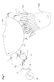
- Fig. 1 shows a schematic representation Transport device 10 according to the invention by a Feed conveyor or a first conveyor 2 supplementary products 1 are supplied by the transport device 10 at a reception point A1 Holding members 20a, ..., 20d detected and after transport at a delivery point A2 of a transport clamp 6 second conveyor 100 (see FIGS. 6 and 7) become.
- the second conveyor shown here, for example 100 and the transport brackets 6 are in the patent EP 0 675 062 B1 described in detail.
- Fig. 7 the supplementary products 1 directly form the band or strip material 3 ', which is from a spindle 4a unwound and fed to a cutting device 90 which supplementary products 1 of the strip material 3 ' separates and feeds the transport device 10.
- the directions of conveyance of the first and second conveyors 2, 100 and the transport device 10 according to the invention lie on one level.
- the required Change of location of the supplementary products 1 takes place as described in detail below, by rotation the holding members 20a, ..., 20d.
- the first conveyor 2, the direction of conveyance with F1 is used to supply supplementary products 1 on a carrier tape 3 by means of a Adhesive layer 1c are attached.
- the adhesive layer 1c is in Form of a strip running in the conveying direction F1 on left side margin of the supplementary products 1 provided.
- the Carrier tape 3 is by means of a spindle 4a stored stock roll unwound and around pulleys 4b, 4c and 4d led to the receiving point Al.
- the carrier tape 3 is pointed Angle led around a release edge 5, so that the Supplementary products 1 are detached from the carrier tape 3 and continue in feed direction F1. That of the Supplementary products 1 freed carrier tape 3 is in a the direction F2 opposite to the feed direction F1 drawn and disposed of.
- the supplementary product supplied on the support element 7a 1 is gripped by the holding element 20a on its upper side la and with the bottom 1b and the exposed Adhesive layer lc directed radially outward about an axis x transported to the delivery point A2 and there on a released further support element 7b.
- the one driven in the direction of rotation around the first axis x Holding member 20a is also rotatable about a second axis y stored, which is at least approximately perpendicular to the first Axis x stands and with the holding member 20a around the first Axis x rotates.
- a second axis y stored, which is at least approximately perpendicular to the first Axis x stands and with the holding member 20a around the first Axis x rotates.
- the supplementary products 1 in the exemplary embodiment Turned 90 ° clockwise so that the on the Adhesive layer 1c of the edge of the supplementary products 1 at the delivery point A2 in relation to the conveying direction F3 of the second conveyor 100 runs on.
- Fig. 3 shows a preferred embodiment of the inventive Device 10 with associated drive and Control devices 12, 14, 15 in detail.
- Fig. 4 shows the Device according to the invention in a cross section along the section line IV-IV entered in Fig. 3.
- the transport device 10 four as Suction tools or suction devices designed holding members 20a, 20b, 20c and 20d, each in a bearing body 22 are rotatably mounted about an axis y, which is perpendicular to Axis x of the drive shaft 11 is.
- the bearing body 22 are with a rotor disk 28, optionally with Rotor arms, connected by means of a flange hub 25 on a shaft 11 aligned along the first axis x is attached. Through the bearing body 22 and the Flange-hub 25 connected rotor disk 28 is thus a formed by the shaft 11 driven rotor 27.
- the holding members 20a, 20b, 20c, 20d have one in the bearing body 22 by means of two bearings 23a and 23b rotatably supported, with an air duct 56 provided hollow shaft 21, the radially outward directed end with one for grasping products 1 suitable suction port 24 is provided and its counter the first axis x directed end into an ejector 55 is used pneumatically with a controllable Compressed air device 15 is connected and as a jet pump serves with suction.
- the compressed air device 15 consists of a rotary valve sitting on the shaft 11 53, each via a line 54 with an ejector 55 connected and rotatable in one by means of a bearing 52 Stator 51 is mounted such that the stator 51 Air is supplied and in the rotary valve 53 for each Holding member 20a, 20b, 20c, 20d an air channel is formed.
- the air pressure (vacuum) inside each hollow shaft 21 becomes depending on the position of the holding members 20a, 20b, 20c, 20d controlled, so that at the recording point A1 Supplementary product 1 sucked in and after transport the delivery point A2 is released again.
- Vacuum system can be used by the need the air is extracted from the corresponding channels.
- Control device 14 has for each of the holding members 20a, 20b, 20c, 20d one in the bearing body 22 slidably mounted slide 32 and a backdrop 40, the Surface by the slider 32 by means of a wheel 31 is scanned.
- the slide 32 has one Tooth profile 33, the form-fitting in a hollow shaft 21 engages provided spur gear. By a Shift of the slide 32 parallel to the first axis x is therefore a corresponding rotation of the Hollow shaft 21 and thus the holding member 20a, 20b, 20c, 20d causes.
- the slide 32 is moved in Dependency of the surface of the backdrop 40 through which thus the rotation of the holding members 20a, 20b, 20c, 20d in Dependency of the angle of rotation of the shaft 11 is fixed.
- the backdrop 40 is on a parallel to the plane of rotation of the rotor 27 arranged mounting plate 41 attached via at least one support element 42 (in FIG. 4 there are two Support elements 42a, 42b shown) with a support structure 18 is connected.
- the support structure 18 has Base element 82 on which the support element 42 (42a, 42b) and two support members 81a, 81b are attached, which with bearings 83a, 83b serving to support the shaft 11 are provided.
- a part of the Shaft drive 12 attached (see Fig. 3 and Fig. 4).
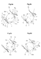
- the Transport clamps 6 is in the takeover section, at Delivery point A2 of the transport device 10, one each Supplementary product 1 at its, in the direction of rotation U seen, trailing edge detected and then, as in Fig. 7 shown, given to printed products 9, which in the Processing device 1000 astride wall elements 1001 are arranged.
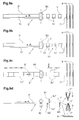
- the transfer is subsequently based on FIGS. 8a to 8d a supplementary product 1 from the first to the second Conveyors 2, 100 by means of the transport device according to the invention 10 described.
- a supplementary product 1 detached and at the reception point A1 on the first Support element 7a is deposited (see Fig. 8a, item a).
- the next holding element 20a becomes the supplementary product placed on the support element 7a 1 held by the bolt 8 (see Fig. 8b, Pos. B).
- Fig. 8c item c
- Supplementary product 1 by folding down the latch 8 released (see Fig. 8d, item d).
- A2 is the registered supplementary product 1 by means of Control device 14 rotated so far about the second axis y until the edge of the Supplementary product 1 in relation to the direction of rotation of the Rotor 27 runs on (see Fig. 8c, item g).
- the holding member 20c has the delivery point in FIG. 8a, item e A2 reaches and then places the transported one Supplementary product 1 on the second support element 7b (see Fig. 8b, item f and 8c, item g). After dropping of the supplementary product 1, this is by the holding member 20c released (see Fig. 8d, item h), so that it, like in Figures 8a-8c, positions i, j and k shown by a transport clamp 6 is grasped and carried away can.
- FIGS. 9a to 9d show further methods of supply and preparation of supplementary products 1 shown for example, as shown in Fig. 7, with printed matter 9 are connected.
- Carrier tape 3 for the supplementary products 1 is shown in Fig. 9a and 9b uses a band 3 'which has an in Conveying direction continuous adhesive layer 1c ' having.
- the tape 3 ' is in front of the recording point a cutting device 90 in supplementary products 1 ' divided, which after the transport process with Printed products 9, i.e. the Pass through the transport device 10 without turning.
- Fig. 9c and Fig. 9d one is not with an adhesive layer provided band 3 "shown by the cutter 90 is broken down into parts according to the Coating by means of adhesive dispensers 91, 92 and / or labeling by means of a print head 93 (e.g. ink jet) form the supplementary products 1 ".
- the parts can e.g. Samples of goods or sample bags that form a ribbon 3 "are joined together.
- Fig. 9d it can also be seen that for assembly printed products provided with supplementary products 1 9 in processing facilities 1000 different can be stored. Since the transport device according to the invention 10 the supplementary products 1 for each type to store a printed product in the required Delivering the situation, it is not only regarding spatial relationships, but also functional versatile. Supplementary products 1 can be found in rotated at any angle around the second axis y and be connected to the printed matter 9, the inserted in slots, astride on Wall elements or placed on a conveyor belt in the Processing device 1000 are stored.
- the required change in position of the supplementary products 1 during the passage of the transport device 10, i.e. the Rotation about the second axis y in a desired Angle and direction of rotation is determined by the shape of the backdrop 40 determined.
- Supplementary products 1 without turning can pass through the transport device 10 for example - as shown in Fig. 3a - the backdrop 40 from that indicated by dash-dotted lines in FIG. 3a Position in the direction of the first axis x in the full Line drawn position in which they are adjusted with the wheels 31 outside the area of engagement located so that the Complementary products 1 from the reception point A1 to the Delivery point A2 does not rotate around the second axis y takes place.
- the backdrop 40 can also in one Intermediate position between the two in Fig. 3a Limit positions shown (dash-dotted - maximum Twisting, e.g. 90 ° full line - no twisting) are held, creating the desired angle of rotation for the Supplementary products 1 is reduced.
- the mounting plate 41 connected to the backdrop 40 a support element 42 'attached to the shaft 11 on the one hand and on a parallel to the shaft 11
- Guide rod 96 is slidably arranged on the other hand.
- the guide rod 96 is connected to the base element 82 connected supporting elements 81b, 81c.
- Mounting plate 41 is a control cylinder 97 between the Mounting plate 41 and the support member 81b arranged.
- Control variant can with the backdrop 40 via the Wheel 31 cooperating slider 32 by means of itself known pawl 98 in a particular one certain angle of rotation of the holding member 20 corresponding Position are blocked and remain in this, too when the wheel 31 is out of engagement with the link 40 reached.
- a control element 99 By means of a control element 99, the Pawl 98 in a dash-dotted line in Fig. 5a position shown are adjusted, and thereby the Blockage caused by a pinch between an opening 98 'of the pawl 98 and the slide circumference, To get picked up.
- This is a selectable individual Turning or not turning by means of the control element 99 enables. It is also conceivable to set the backdrop 40 on the Mounting plate 41 to rotate the shaft 11 such that the active area of the backdrop 40 outside the Funding area.
- Transport device 10 with less or more than the four shown holding members 20a, ..., 20d.
- the Number of holding members 20 is preferably below Taking into account the size of the supplementary products 1 chosen.
- the supplementary products 1 in its upper area captured on its underside and with this also released on the support element 7b, previously (For example, by turning the 20b Holding member) a twisting of the supplementary products 1 in a desired angle of rotation can take place.
- the transport device 10 can of course be used also for the transport of supplementary products 1 used at the reception point in stacked form.
- a single supplement 1 can be of an auxiliary tool, an additional Suction cup or a cutting knife, raised or by a holding member 20a, 20b, 20c, 20d can be detected directly.
- the supplementary products 1, 1 ', 1 " can therefore by arbitrary first conveyor devices 2, 2 ', 2' 'fed and prepared by the transport device according to the invention 10 transported and in a required Positioned and by any second and others Conveyors 100, 1000 are processed further.
- supplementary products that do not have an adhesive layer can be provided by the transport device according to the invention 10 advantageously transported and in a desired location.
- the supplementary products are preferably lighter printed products, for example Notes in the manner of "Post-it” ® products, with samples or information documents provided with content, to connect with the print products are.
- the transport device 10 is also used the first and second conveyors 2; 100 preferably synchronized in such a way that a smooth transfer of the Supplementary products 1 is possible.
- transport device 10 the transported supplementary products 1 at the delivery point A2 directly to printed products or attaching other products.
- Supplementary products 1 can also be transported that are not coated with adhesive, and in Printed products or other products inserted (e.g. an advertising letter in a daily newspaper).
Abstract
Description
- Fig. 1
- in perspektivischer Darstellung eine erfindungsgemässe Transportvorrichtung, der von einem ersten Förderer Ergänzungsprodukte zugeführt werden, die nach dem Transport und gegebenenfalls einer Lageänderung von einer Transportklammer eines zweiten Förderers erfasst werden;
- Fig. 2
- in Seitenansicht die Transportklammer von Fig. 1 beim Erfassen eines Ergänzungsproduktes;
- Fig. 3
- in Ansicht und teilweise geschnitten eine erfindungsgemässe Transportvorrichtung mit Antriebs- und Steuereinrichtungen;
- Fig. 3a
- eine der Fig. 3 entsprechende Darstellung mit einer zweiten Variante einer Steuereinrichtung;
- Fig. 4
- in Seitenansicht die erfindungsgemässe Transportvorrichtung teilweise geschnitten entlang der in Fig. 3 eingetragenen Schnittlinie IV-IV;
- Fig. 5
- die erfindungsgemässe Transportvorrichtung in einem Schnitt entlang der in Fig. 3 eingetragenen Schnittlinie V-V;
- Fig. 5a
- eine der Fig. 5 entsprechende Darstellung mit einer dritten Variante einer Steuereinrichtung;
- Fig. 6
- eine erfindungsgemässe Transportvorrichtung, die Ergänzungsprodukte von einem ersten Förderer übernimmt und an einen zweiten Förderer abgibt;
- Fig. 6a
- eine der Fig. 6 entsprechende Darstellung mit einer zweiten Variante des ersten Förderers;
- Fig. 6b
- eine der Fig. 6 entsprechende Darstellung mit einer dritten Variante des ersten Förderers;
- Fig. 7
- die Transportvorrichtung von Fig. 6 in Zusammenarbeit mit einer Verarbeitungseinrichtung, in der mit Ergänzungsprodukten zu bestückende Druckereiprodukte angeordnet sind;
- Fig. 8a-d
- die Transportvorrichtung von Fig. 6 während verschiedenen Phasen beim Transport von Ergänzungsprodukten und
- Fig. 9a-d
- die Vorbereitung von Ergänzunsprodukten sowie deren Anordnung nach deren Verbindung mit einem in der Verarbeitungseinrichtung abgelegten Druckereierzeugnis.
Claims (18)
- Vorrichtung (10) zum Transport von insbesondere mit Haftmittel versehenen flächigen Ergänzungsprodukten (1) von einer Aufnahmestelle (A1) zu einer Abgabestelle (A2), mit wenigstens einem entlang einer in sich geschlossenen Umlaufbahn bewegten Halteorgan (20a, 20b, 20c, 20d), mittels dem Ergänzungsprodukte (1) an der Aufnahmestelle (A1) erfasst und an der Abgabestelle (A2) wieder freigegeben werden können, dadurch gekennzeichnet, dass das Halteorgan (20a, 20b, 20c, 20d) um eine zumindest annähernd senkrecht zur Umlaufbahn stehende Achse y drehbar gelagert ist und eine umstellbare Steuereinrichtung (14) dazu bestimmt ist, das Halteorgan (20a, 20b, 20c, 20d) während des Transports von der Aufnahme- zur Abgabestelle (A1; A2) wahlweise in einer Drehstellung unverändert zu belassen oder um die Achse y um einen bestimmten Winkel zu drehen, bis eine zur Weiterverarbeitung vorgesehene Endlage des transportierten Ergänzungsproduktes (1) erreicht ist.
- Vorrichtung (10) nach Anspruch 1, dadurch gekennzeichnet, dass das Halteorgan (20a; 20b; 20c; 20d) in einem entlang der Umlaufbahn bewegten Lagerkörper (22) drehbar gelagert ist, dass die Steuereinrichtung (14) eine Kulisse (40) sowie einen im Lagerkörper (22) verschiebbar gelagerten Schieber (32) aufweist, der während der Bewegung des Halteorgans (20a; 20b; 20c; 20d) entlang der Umlaufbahn zum Abtasten der Oberfläche der Kulisse (40) und zum dazu entsprechenden Drehen des Halteorgans (20a; 20b; 20c; 20d) um die Achse y bestimmt ist.
- Vorrichtung (10) nach Anspruch 1 oder 2, dadurch gekennzeichnet, dass die Ergänzungsprodukte (1) mittels der eingeschalteten Steuereinrichtung (14) zwischen Aufnahmestelle (A1) und Abgabestelle (A2) um vorzugsweise 90° drehbar sind.
- Vorrichtung (10) nach einem der Ansprüche 1 bis 3, dadurch gekennzeichnet, dass die Steuereinrichtung (14) derart umschaltbar ist, dass der Drehwinkel, um welchen das Halteorgan (20a; 20b; 20c; 20d) während des Transports von der Aufnahme- zur Abgabestelle (A1; A2) gedreht wird, veränderbar ist.
- Vorrichtung (10) nach einem der Ansprüche 1-4, dadurch gekennzeichnet, dass mehrere Halteorgane (20a, 20b, 20c, 20d) in gleichmässigen Abständen hintereinander an einem in sich geschlossenen Zugorgan oder an einer um eine Achse x drehenden Rotorscheibe (28) oder an Rotorarmen eines um die Achse x drehenden Rotors (27) angeordnet sind.
- Vorrichtung (10) nach einem der Ansprüche 1-5, dadurch gekennzeichnet, dass die Halteorgane (20a, 20b, 20c, 20d) als Saugorgane oder Greifer ausgestaltet und zum Ansaugen bzw. Ergreifen der Ergänzungsprodukte (1) bestimmt sind.
- Vorrichtung (10) nach einem der Ansprüche 1-6, dadurch gekennzeichnet, dass an der Aufnahmestelle (A1) ein erstes Auflageelement (7a) vorgesehen ist, auf das die Ergänzungsprodukte (1) durch einen ersten Förder (2) abgelegt und mittels den Halteorganen (20a, 20b, 20c, 20d) einzelweise erfasst werden und dass an der Abgabestelle (A2) ein zweites Auflageelement (7b) vorgesehen ist, auf das die transportierten Ergänzungsprodukte (1) abgelegt und für die Aufnahme durch einen zweiten Förderer (100) bereit gehalten werden.
- Vorrichtung nach einem der Ansprüche 1-7, dadurch gekennzeichnet, dass die als Saugorgane ausgestalteten Halteorgane (20a, 20b, 20c, 20d) einen im Lagerkörper (22) drehbar gelagerten Hohlschaft (21) aufweisen, dessen radial nach aussen gerichtetes Ende mit einem zum Erfassen von Ergänzungsprodukten (1) geeigneten Saugkopf (24) versehen ist und dessen gegen die Umlaufbahn gerichtetes Ende pneumatisch mit einer steuerbaren Druckluftvorrichtung (15) verbunden ist.
- Vorrichtung nach Anspruch 8, dadurch gekennzeichnet, dass die Druckluftvorrichtung (15) zur Erzeugung eines Unterdrucks im Hohlschaft (21) bestimmt ist, indem die Luft in der mit dem Hohlschaft (21) verbundenen Leitung (54) abgesaugt wird oder indem durch die Leitung (54) Luft mit erhöhter Strömungsgeschwindigkeit durch einen Ejector (55) geführt wird, an den der Hohlschaft (21) an einer Stelle mit vorzugsweise maximaler Strömungsgeschwindigkeit pneumatisch angekoppelt ist.
- Vorrichtung nach einem der Ansprüche 8-9, dadurch gekennzeichnet, dass der Hohlschaft (21) eine Stirnverzahnung aufweist, in die der zumindest annähernd parallel zur Umlaufbahn bzw. zur Achse x verschiebbare Schieber (32) formschlüssig eingreift.
- Vorrichtung nach einem der Ansprüche 1-10, dadurch gekennzeichnet, dass ein erster Förderer (2) vorgesehen ist, durch den den Halteorganen (20a, 20b, 20c, 20d) Ergänzungsprodukte (1, 1', 1") zuführbar sind, die an der Aufnahmestelle (A1) von einem Stapel oder von einem Band oder Trägerband (3, 3', 3'') abtrennbar sind.
- Vorrichtung nach Anspruch 11, dadurch gekennzeichnet, dass die Ergänzungsprodukte (1, 1', 1") mit einer Haftschicht (1c, 1c') versehen sind oder während des Transportvorgangs mit einer Haftschicht (1c") versehen und/oder mittels einem Druckkopf (93) bedruckt werden.
- Vorrichtung nach einem der Ansprüche 1-12, dadurch gekennzeichnet, dass die Ergänzungsprodukte (1, 1', 1") an der Abgabestelle (A2) durch Transportklammern (6) des zweiten Förderers (100) ergreifbar sind.
- Vorrichtung nach Anspruch 13, dadurch gekennzeichnet, dass die Ergänzungsprodukte (1, 1', 1") mittels der Transportklammern (6) in oder an Druckereierzeugnisse (9) abgebbar bzw. anheftbar sind, die in einer Verarbeitungseinrichtung (1000) gesammelt oder eingesteckt sind.
- Vorrichtung nach einem der Ansprüche 1-14, dadurch gekennzeichnet, dass die Halteorgane (20a, 20b, 20c, 20d) individuell ansteuerbar sind.
- Verfahren zum Transport von insbesondere mit Haftmittel versehenen flächigen Ergänzungsprodukten (1) von einer Aufnahmestelle (A1) zu einer Abgabestelle (A2), wobei die Ergänzungsprodukte (1) mittels eines entlang einer in sich geschlossenen Umlaufbahn bewegten Halteorgans (20a, 20b, 20c, 20d) an der Aufnahmestelle (A1) erfasst und an der Abgabestelle (A2) wieder freigegeben werden, dadurch gekennzeichnet, dass das um eine zumindest annähernd senkrecht zur Umlaufbahn stehende Achse y drehbar gelagerte Halteorgan (20a, 20b, 20c, 20d) während des Transports von der Aufnahme- zur Abgabestelle (A1; A2) wahlweise in einer Drehstellung unverändert belassen wird oder um die Achse y um einen bestimmten Winkel gedreht wird, bis eine zur Weiterverarbeitung vorgesehene Endlage des transportierten Ergänzungsproduktes (1) erreicht ist.
- Verfahren nach Anspruch 16, dadurch gekennzeichnet, dass die von einem ersten Förderer (2) in einer ersten Lage zugeführten Ergänzungsprodukte (1) erfasst, zur Abgabestelle (A2) transportiert und dort gegebenenfalls einem zweiten Förderer (100) in einer für die Weiterverarbeitung geeigneten zweiten Lage abgegeben werden.
- Verfahren nach Anspruch 17, dadurch gekennzeichnet, dass die Förderrichtungen des ersten und/oder des zweiten Förderers (2; 100) sowie der Halteorgane (20a, 20b, 20c, 20d) in einer Ebene liegen.
Applications Claiming Priority (2)
| Application Number | Priority Date | Filing Date | Title |
|---|---|---|---|
| CH224199 | 1999-12-07 | ||
| CH224199 | 1999-12-07 |
Publications (2)
| Publication Number | Publication Date |
|---|---|
| EP1106550A1 true EP1106550A1 (de) | 2001-06-13 |
| EP1106550B1 EP1106550B1 (de) | 2004-02-18 |
Family
ID=4229161
Family Applications (1)
| Application Number | Title | Priority Date | Filing Date |
|---|---|---|---|
| EP00125755A Expired - Lifetime EP1106550B1 (de) | 1999-12-07 | 2000-11-24 | Vorrichtung und Verfahren zum Transport von Ergänzungsprodukten |
Country Status (9)
| Country | Link |
|---|---|
| US (1) | US6520496B2 (de) |
| EP (1) | EP1106550B1 (de) |
| JP (1) | JP4761237B2 (de) |
| AT (1) | ATE259747T1 (de) |
| AU (1) | AU775822B2 (de) |
| CA (1) | CA2327774C (de) |
| DE (1) | DE50005320D1 (de) |
| DK (1) | DK1106550T3 (de) |
| ES (1) | ES2211440T3 (de) |
Cited By (1)
| Publication number | Priority date | Publication date | Assignee | Title |
|---|---|---|---|---|
| CH705738A1 (de) * | 2011-11-11 | 2013-05-15 | Ferag Ag | Verfahren zum Applizieren von flächigen Ergänzungsprodukten an Basisprodukten sowie Vorrichtung zur Durchführung des Verfahrens. |
Families Citing this family (6)
| Publication number | Priority date | Publication date | Assignee | Title |
|---|---|---|---|---|
| EP1683612B1 (de) * | 2005-01-21 | 2016-08-03 | Ferag AG | Verfahren und Vorrichtung zum Transportieren von flexiblen flächigen Produkten und gleichzeitigen Beschneiden derselben |
| CH711986B1 (de) | 2006-10-13 | 2017-06-30 | Ferag Ag | Verfahren und System zur Individualisierung eines Druckproduktes. |
| US9061832B2 (en) * | 2011-11-21 | 2015-06-23 | R.A. Jones & Co. | Pouch transfer apparatus and methods |
| US8939445B2 (en) * | 2013-05-30 | 2015-01-27 | Kimberly-Clark Worldwide, Inc. | Vacuum roll with internal rotary valve |
| JP6721624B2 (ja) * | 2018-03-27 | 2020-07-15 | ファナック株式会社 | ラベル剥がし機能付きラベル貼付装置、ロボット、およびラベル剥がし方法 |
| CN110304438A (zh) * | 2019-07-22 | 2019-10-08 | 黄山富田精工制造有限公司 | 上料组件及采用该组件的上料机器人 |
Citations (9)
| Publication number | Priority date | Publication date | Assignee | Title |
|---|---|---|---|---|
| FR2420499A1 (fr) * | 1978-03-23 | 1979-10-19 | Ferag Ag | Dispositif pour former une ligne derivee continue, a partir d'une ligne principale continue d'articles plats, en particulier d'imprimes |
| US4394898A (en) * | 1981-04-23 | 1983-07-26 | Paper Converting Machine Company | Method and apparatus for providing balanced stacks of diapers |
| US4787953A (en) * | 1987-01-12 | 1988-11-29 | Hobart Corporation | Apparatus for label transfer |
| EP0355292A2 (de) * | 1984-04-23 | 1990-02-28 | Kimberly-Clark Corporation | Drehbare Überführungswalze |
| EP0450650A1 (de) * | 1990-04-06 | 1991-10-09 | Kimberly-Clark Corporation | Applikator und Methode um einen Materialstreifen zu drehen und auf ein Band zu plazieren |
| EP0570339A1 (de) * | 1992-05-13 | 1993-11-18 | Grapha-Holding Ag | Einrichtung zum klebeartigen Beiheften von Beilagen |
| US5447219A (en) * | 1993-12-06 | 1995-09-05 | Cloud Corporation | Positioning mechanism for high speed packaging machinery |
| US5740900A (en) * | 1995-07-20 | 1998-04-21 | Heidelberger Druckmaschinen Ag | Apparatus for splitting a product stream |
| EP0897871A1 (de) * | 1997-08-20 | 1999-02-24 | SITMA S.p.A. | Vorrichtung zum Drehen eines einer Etikettiermaschine zugeführten Etiketts |
Family Cites Families (13)
| Publication number | Priority date | Publication date | Assignee | Title |
|---|---|---|---|---|
| US2108280A (en) * | 1937-05-08 | 1938-02-15 | Diamond Match Co | Machine for packing book matches |
| CH599891A5 (de) * | 1975-07-30 | 1978-06-15 | Sapal Plieuses Automatiques | |
| DE2901800A1 (de) * | 1979-01-18 | 1980-07-24 | Becker & Van Huellen | Verfahren und vorrichtung zur kontrolle der unterseite von plattenfoermigen gegenstaenden |
| JPS60153378U (ja) * | 1984-03-16 | 1985-10-12 | 富士通株式会社 | 媒体回動機構 |
| US4696715A (en) * | 1986-02-11 | 1987-09-29 | Mgs Machine Corporation | Pick-and-place glue applicator |
| DE3605534A1 (de) * | 1986-02-20 | 1987-08-27 | Rotaprint Gmbh | Bogen-foerderer fuer bogenverarbeitende maschinen |
| JPH0331145A (ja) * | 1989-06-28 | 1991-02-08 | Canon Inc | シート材無端搬送装置 |
| JP3348119B2 (ja) * | 1993-10-04 | 2002-11-20 | 富士写真フイルム株式会社 | ラベル貼付け装置及びこれに用いるラベル台紙 |
| US5535999A (en) * | 1994-03-11 | 1996-07-16 | Axia Incorporated | Apparatus for rotating a flat article through a desired angular orientation |
| EP0675062B1 (de) | 1994-03-24 | 1997-12-17 | Ferag AG | Vorrichtung zum Zubringen von flächigen Erzeugnissen zu einer Verarbeitungseinrichtung für Druckereiprodukte |
| US6116317A (en) * | 1996-06-21 | 2000-09-12 | Tharpe, Jr.; John M. | Apparatus having a core orientor and methods of orienting portions of a disposable undergarment |
| NL1006706C2 (nl) | 1997-08-01 | 1999-02-02 | Vianen De Binderijgroep Bv | Werkwijze en inrichting voor het aanbrengen van vellen materiaal op zich in een rij voortbewegende katernen. |
| NL1012982C2 (nl) * | 1999-04-29 | 2000-11-06 | Kl Ckner Honsel Tevopharm B V | Roteerbare grijperinrichting. |
-
2000
- 2000-11-24 AT AT00125755T patent/ATE259747T1/de active
- 2000-11-24 EP EP00125755A patent/EP1106550B1/de not_active Expired - Lifetime
- 2000-11-24 DK DK00125755T patent/DK1106550T3/da active
- 2000-11-24 ES ES00125755T patent/ES2211440T3/es not_active Expired - Lifetime
- 2000-11-24 DE DE50005320T patent/DE50005320D1/de not_active Expired - Lifetime
- 2000-12-06 US US09/731,233 patent/US6520496B2/en not_active Expired - Fee Related
- 2000-12-06 AU AU72063/00A patent/AU775822B2/en not_active Ceased
- 2000-12-06 JP JP2000371377A patent/JP4761237B2/ja not_active Expired - Fee Related
- 2000-12-06 CA CA002327774A patent/CA2327774C/en not_active Expired - Fee Related
Patent Citations (9)
| Publication number | Priority date | Publication date | Assignee | Title |
|---|---|---|---|---|
| FR2420499A1 (fr) * | 1978-03-23 | 1979-10-19 | Ferag Ag | Dispositif pour former une ligne derivee continue, a partir d'une ligne principale continue d'articles plats, en particulier d'imprimes |
| US4394898A (en) * | 1981-04-23 | 1983-07-26 | Paper Converting Machine Company | Method and apparatus for providing balanced stacks of diapers |
| EP0355292A2 (de) * | 1984-04-23 | 1990-02-28 | Kimberly-Clark Corporation | Drehbare Überführungswalze |
| US4787953A (en) * | 1987-01-12 | 1988-11-29 | Hobart Corporation | Apparatus for label transfer |
| EP0450650A1 (de) * | 1990-04-06 | 1991-10-09 | Kimberly-Clark Corporation | Applikator und Methode um einen Materialstreifen zu drehen und auf ein Band zu plazieren |
| EP0570339A1 (de) * | 1992-05-13 | 1993-11-18 | Grapha-Holding Ag | Einrichtung zum klebeartigen Beiheften von Beilagen |
| US5447219A (en) * | 1993-12-06 | 1995-09-05 | Cloud Corporation | Positioning mechanism for high speed packaging machinery |
| US5740900A (en) * | 1995-07-20 | 1998-04-21 | Heidelberger Druckmaschinen Ag | Apparatus for splitting a product stream |
| EP0897871A1 (de) * | 1997-08-20 | 1999-02-24 | SITMA S.p.A. | Vorrichtung zum Drehen eines einer Etikettiermaschine zugeführten Etiketts |
Cited By (2)
| Publication number | Priority date | Publication date | Assignee | Title |
|---|---|---|---|---|
| CH705738A1 (de) * | 2011-11-11 | 2013-05-15 | Ferag Ag | Verfahren zum Applizieren von flächigen Ergänzungsprodukten an Basisprodukten sowie Vorrichtung zur Durchführung des Verfahrens. |
| EP2592031A1 (de) | 2011-11-11 | 2013-05-15 | Ferag AG | Verfahren zum Applizieren von flächigen Ergänzungsprodukten an Basisprodukten sowie Vorrichtung zur Durchführung des Verfahrens |
Also Published As
| Publication number | Publication date |
|---|---|
| ES2211440T3 (es) | 2004-07-16 |
| DE50005320D1 (de) | 2004-03-25 |
| AU775822B2 (en) | 2004-08-19 |
| AU7206300A (en) | 2001-06-14 |
| US6520496B2 (en) | 2003-02-18 |
| JP2001206586A (ja) | 2001-07-31 |
| US20020125630A1 (en) | 2002-09-12 |
| DK1106550T3 (da) | 2004-03-15 |
| CA2327774C (en) | 2008-08-26 |
| ATE259747T1 (de) | 2004-03-15 |
| EP1106550B1 (de) | 2004-02-18 |
| CA2327774A1 (en) | 2001-06-07 |
| JP4761237B2 (ja) | 2011-08-31 |
Similar Documents
| Publication | Publication Date | Title |
|---|---|---|
| EP0795503B1 (de) | Verfahren und Vorrichtung zum Ausrichten von flachen Gegenständen | |
| WO1998003419A1 (de) | Vorrichtung zum zubringen von druckereierzeugnissen zu verarbeitungsstationen | |
| EP0675005A1 (de) | Einrichtung zum Klebebinden von Druckereiprodukten | |
| DE3603285C2 (de) | Zusammentragmaschine | |
| DE102006005156A1 (de) | Vorrichtung zum Ablegen von einzeln aufeinanderfolgend zugeführten Druckprodukten in einer geschuppt übereinanderliegenden Formation | |
| EP2133295B1 (de) | Vorrichtung und Verfahren zum Entnehmen flacher Druckprodukte aus einem Stapel und zum Übergeben der Druckprodukte an eine laufende Transportvorrichtung | |
| EP1106550B1 (de) | Vorrichtung und Verfahren zum Transport von Ergänzungsprodukten | |
| EP0551055B1 (de) | Verfahren und Vorrichtung zum Sammeln bzw. Zusammentragen von Druckprodukten | |
| EP1351873B1 (de) | Vorrichtung zum verarbeiten von druckereiprodukten | |
| DE2915689C2 (de) | Vorrichtung zur lagerichtigen Abgabe von von einer Materialbahn abgetrennten Abschnitten | |
| EP1112861B1 (de) | Verfahren und Vorrichtung zum Verbinden von Ergänzungsprodukten mit Druckereierzeugnissen | |
| EP0540865B1 (de) | Vorrichtung zum Ankleben von Beilagen an Druckereiprodukte | |
| EP2301874B1 (de) | Verfahren zum Sammeln von Druckprodukten sowie Sammeleinrichtung für Druckprodukte | |
| EP1086914B1 (de) | Vorrichtung zum Transport von flexiblen, flächigen Erzeugnissen | |
| EP1669312B1 (de) | Vorrichtung zum on-line Weitertransport von flachen Gegenständen, die von einer zuführenden Vorrichtung auf einem Träger gestapelt werden | |
| EP1612174B1 (de) | Vorrichtung zur Ausrichtung von in einer Lage übereinander angeordneten Bogen | |
| EP1050499A1 (de) | Vorrichtung zum Zuführen von flächigen Gegenständen zu einer Verarbeitungseinrichtung | |
| EP0806391A1 (de) | Vorrichtung zum Zubringen von Druckereierzeugnissen zu einer Weiterverarbeitungsstelle | |
| EP0570339A1 (de) | Einrichtung zum klebeartigen Beiheften von Beilagen | |
| EP1186558A1 (de) | Vorrichtung zur Beschickung einer Verarbeitungsstrecke mit Druckprodukten | |
| EP1020385B1 (de) | Vorrichtung zum Beschicken einer Verarbeitungsstrecke mit Druckprodukten | |
| DE19915387A1 (de) | System zum angepaßten Zuführen eines geschuppten Stromes bogenförmiger Produkte | |
| DE2930088A1 (de) | Verfahren und vorrichtung zur zufoerderung von bogen zu einer bogen verarbeitenden maschine | |
| EP0709218A1 (de) | Verfahren und Einrichtung zum Beschriften von Druckereiprodukten | |
| EP1669313B1 (de) | Verfahren und Vorrichtung zum Weitertransport und gegebenenfalls zur Weiterverarbeitung von Bogen, die von einer bogenverarbeitenden Maschine ausgelegt werden |
Legal Events
| Date | Code | Title | Description |
|---|---|---|---|
| PUAI | Public reference made under article 153(3) epc to a published international application that has entered the european phase |
Free format text: ORIGINAL CODE: 0009012 |
|
| AK | Designated contracting states |
Kind code of ref document: A1 Designated state(s): AT BE CH CY DE DK ES FI FR GB GR IE IT LI LU MC NL PT SE TR |
|
| AX | Request for extension of the european patent |
Free format text: AL;LT;LV;MK;RO;SI |
|
| 17P | Request for examination filed |
Effective date: 20010423 |
|
| 17Q | First examination report despatched |
Effective date: 20011102 |
|
| AKX | Designation fees paid |
Free format text: AT BE CH CY DE DK ES FI FR GB GR IE IT LI LU MC NL PT SE TR |
|
| GRAH | Despatch of communication of intention to grant a patent |
Free format text: ORIGINAL CODE: EPIDOS IGRA |
|
| GRAP | Despatch of communication of intention to grant a patent |
Free format text: ORIGINAL CODE: EPIDOSNIGR1 |
|
| GRAS | Grant fee paid |
Free format text: ORIGINAL CODE: EPIDOSNIGR3 |
|
| GRAA | (expected) grant |
Free format text: ORIGINAL CODE: 0009210 |
|
| AK | Designated contracting states |
Kind code of ref document: B1 Designated state(s): AT BE CH CY DE DK ES FI FR GB GR IE IT LI LU MC NL PT SE TR |
|
| PG25 | Lapsed in a contracting state [announced via postgrant information from national office to epo] |
Ref country code: IE Free format text: LAPSE BECAUSE OF FAILURE TO SUBMIT A TRANSLATION OF THE DESCRIPTION OR TO PAY THE FEE WITHIN THE PRESCRIBED TIME-LIMIT Effective date: 20040218 Ref country code: TR Free format text: LAPSE BECAUSE OF FAILURE TO SUBMIT A TRANSLATION OF THE DESCRIPTION OR TO PAY THE FEE WITHIN THE PRESCRIBED TIME-LIMIT Effective date: 20040218 Ref country code: CY Free format text: LAPSE BECAUSE OF FAILURE TO SUBMIT A TRANSLATION OF THE DESCRIPTION OR TO PAY THE FEE WITHIN THE PRESCRIBED TIME-LIMIT Effective date: 20040218 |
|
| REG | Reference to a national code |
Ref country code: GB Ref legal event code: FG4D Free format text: NOT ENGLISH |
|
| REG | Reference to a national code |
Ref country code: SE Ref legal event code: TRGR |
|
| REG | Reference to a national code |
Ref country code: CH Ref legal event code: NV Representative=s name: PATENTANWAELTE SCHAAD, BALASS, MENZL & PARTNER AG Ref country code: CH Ref legal event code: EP |
|
| GBT | Gb: translation of ep patent filed (gb section 77(6)(a)/1977) |
Effective date: 20040218 |
|
| REG | Reference to a national code |
Ref country code: DK Ref legal event code: T3 |
|
| REG | Reference to a national code |
Ref country code: IE Ref legal event code: FG4D Free format text: GERMAN |
|
| REF | Corresponds to: |
Ref document number: 50005320 Country of ref document: DE Date of ref document: 20040325 Kind code of ref document: P |
|
| PG25 | Lapsed in a contracting state [announced via postgrant information from national office to epo] |
Ref country code: GR Free format text: LAPSE BECAUSE OF FAILURE TO SUBMIT A TRANSLATION OF THE DESCRIPTION OR TO PAY THE FEE WITHIN THE PRESCRIBED TIME-LIMIT Effective date: 20040518 |
|
| REG | Reference to a national code |
Ref country code: ES Ref legal event code: FG2A Ref document number: 2211440 Country of ref document: ES Kind code of ref document: T3 |
|
| REG | Reference to a national code |
Ref country code: IE Ref legal event code: FD4D |
|
| ET | Fr: translation filed | ||
| PG25 | Lapsed in a contracting state [announced via postgrant information from national office to epo] |
Ref country code: LU Free format text: LAPSE BECAUSE OF NON-PAYMENT OF DUE FEES Effective date: 20041124 |
|
| PG25 | Lapsed in a contracting state [announced via postgrant information from national office to epo] |
Ref country code: MC Free format text: LAPSE BECAUSE OF NON-PAYMENT OF DUE FEES Effective date: 20041130 |
|
| PLBE | No opposition filed within time limit |
Free format text: ORIGINAL CODE: 0009261 |
|
| STAA | Information on the status of an ep patent application or granted ep patent |
Free format text: STATUS: NO OPPOSITION FILED WITHIN TIME LIMIT |
|
| 26N | No opposition filed |
Effective date: 20041119 |
|
| REG | Reference to a national code |
Ref country code: CH Ref legal event code: PFA Owner name: FERAG AG Free format text: FERAG AG#ZUERICHSTRASSE 74#8340 HINWIL (CH) -TRANSFER TO- FERAG AG#PATENTABTEILUNG Z. H. MARKUS FELIX ZUERICHSTRASSE 74#8340 HINWIL (CH) |
|
| PG25 | Lapsed in a contracting state [announced via postgrant information from national office to epo] |
Ref country code: PT Free format text: LAPSE BECAUSE OF NON-PAYMENT OF DUE FEES Effective date: 20040718 |
|
| PGFP | Annual fee paid to national office [announced via postgrant information from national office to epo] |
Ref country code: GB Payment date: 20101118 Year of fee payment: 11 |
|
| PGFP | Annual fee paid to national office [announced via postgrant information from national office to epo] |
Ref country code: ES Payment date: 20111125 Year of fee payment: 12 Ref country code: FI Payment date: 20111114 Year of fee payment: 12 Ref country code: FR Payment date: 20111130 Year of fee payment: 12 |
|
| PGFP | Annual fee paid to national office [announced via postgrant information from national office to epo] |
Ref country code: BE Payment date: 20111110 Year of fee payment: 12 |
|
| BERE | Be: lapsed |
Owner name: *FERAG A.G. Effective date: 20121130 |
|
| GBPC | Gb: european patent ceased through non-payment of renewal fee |
Effective date: 20121124 |
|
| REG | Reference to a national code |
Ref country code: FR Ref legal event code: ST Effective date: 20130731 |
|
| PG25 | Lapsed in a contracting state [announced via postgrant information from national office to epo] |
Ref country code: BE Free format text: LAPSE BECAUSE OF NON-PAYMENT OF DUE FEES Effective date: 20121130 Ref country code: FI Free format text: LAPSE BECAUSE OF NON-PAYMENT OF DUE FEES Effective date: 20121124 |
|
| PG25 | Lapsed in a contracting state [announced via postgrant information from national office to epo] |
Ref country code: GB Free format text: LAPSE BECAUSE OF NON-PAYMENT OF DUE FEES Effective date: 20121124 Ref country code: FR Free format text: LAPSE BECAUSE OF NON-PAYMENT OF DUE FEES Effective date: 20121130 |
|
| REG | Reference to a national code |
Ref country code: ES Ref legal event code: FD2A Effective date: 20140513 |
|
| PG25 | Lapsed in a contracting state [announced via postgrant information from national office to epo] |
Ref country code: ES Free format text: LAPSE BECAUSE OF NON-PAYMENT OF DUE FEES Effective date: 20121125 |
|
| PGFP | Annual fee paid to national office [announced via postgrant information from national office to epo] |
Ref country code: DK Payment date: 20151118 Year of fee payment: 16 Ref country code: IT Payment date: 20151125 Year of fee payment: 16 |
|
| PGFP | Annual fee paid to national office [announced via postgrant information from national office to epo] |
Ref country code: AT Payment date: 20151119 Year of fee payment: 16 Ref country code: NL Payment date: 20151118 Year of fee payment: 16 Ref country code: SE Payment date: 20151118 Year of fee payment: 16 |
|
| REG | Reference to a national code |
Ref country code: DK Ref legal event code: EBP Effective date: 20161130 |
|
| REG | Reference to a national code |
Ref country code: SE Ref legal event code: EUG |
|
| REG | Reference to a national code |
Ref country code: NL Ref legal event code: MM Effective date: 20161201 |
|
| REG | Reference to a national code |
Ref country code: AT Ref legal event code: MM01 Ref document number: 259747 Country of ref document: AT Kind code of ref document: T Effective date: 20161124 |
|
| PG25 | Lapsed in a contracting state [announced via postgrant information from national office to epo] |
Ref country code: SE Free format text: LAPSE BECAUSE OF NON-PAYMENT OF DUE FEES Effective date: 20161125 Ref country code: AT Free format text: LAPSE BECAUSE OF NON-PAYMENT OF DUE FEES Effective date: 20161124 |
|
| PG25 | Lapsed in a contracting state [announced via postgrant information from national office to epo] |
Ref country code: NL Free format text: LAPSE BECAUSE OF NON-PAYMENT OF DUE FEES Effective date: 20161201 |
|
| PG25 | Lapsed in a contracting state [announced via postgrant information from national office to epo] |
Ref country code: IT Free format text: LAPSE BECAUSE OF NON-PAYMENT OF DUE FEES Effective date: 20161124 |
|
| PG25 | Lapsed in a contracting state [announced via postgrant information from national office to epo] |
Ref country code: DK Free format text: LAPSE BECAUSE OF NON-PAYMENT OF DUE FEES Effective date: 20161130 |
|
| PGFP | Annual fee paid to national office [announced via postgrant information from national office to epo] |
Ref country code: DE Payment date: 20171121 Year of fee payment: 18 |
|
| PGFP | Annual fee paid to national office [announced via postgrant information from national office to epo] |
Ref country code: CH Payment date: 20180131 Year of fee payment: 18 |
|
| REG | Reference to a national code |
Ref country code: DE Ref legal event code: R119 Ref document number: 50005320 Country of ref document: DE |
|
| REG | Reference to a national code |
Ref country code: CH Ref legal event code: PL |
|
| PG25 | Lapsed in a contracting state [announced via postgrant information from national office to epo] |
Ref country code: LI Free format text: LAPSE BECAUSE OF NON-PAYMENT OF DUE FEES Effective date: 20181130 Ref country code: CH Free format text: LAPSE BECAUSE OF NON-PAYMENT OF DUE FEES Effective date: 20181130 |
|
| PG25 | Lapsed in a contracting state [announced via postgrant information from national office to epo] |
Ref country code: DE Free format text: LAPSE BECAUSE OF NON-PAYMENT OF DUE FEES Effective date: 20190601 |