EP1106230A1 - Herstellung einer Filterkassette mit Faltenbalg und Werkzeug mit Sägezahnprofil - Google Patents
Herstellung einer Filterkassette mit Faltenbalg und Werkzeug mit Sägezahnprofil Download PDFInfo
- Publication number
- EP1106230A1 EP1106230A1 EP00122660A EP00122660A EP1106230A1 EP 1106230 A1 EP1106230 A1 EP 1106230A1 EP 00122660 A EP00122660 A EP 00122660A EP 00122660 A EP00122660 A EP 00122660A EP 1106230 A1 EP1106230 A1 EP 1106230A1
- Authority
- EP
- European Patent Office
- Prior art keywords
- bellows
- profiles
- tool
- filter
- exemptions
- Prior art date
- Legal status (The legal status is an assumption and is not a legal conclusion. Google has not performed a legal analysis and makes no representation as to the accuracy of the status listed.)
- Withdrawn
Links
- 238000004519 manufacturing process Methods 0.000 title claims description 9
- 238000000034 method Methods 0.000 claims abstract description 13
- 239000004033 plastic Substances 0.000 claims abstract description 9
- 238000001746 injection moulding Methods 0.000 claims abstract description 8
- 238000002347 injection Methods 0.000 claims description 12
- 239000007924 injection Substances 0.000 claims description 12
- 238000007789 sealing Methods 0.000 claims description 4
- 238000003825 pressing Methods 0.000 claims description 2
- 239000000463 material Substances 0.000 description 5
- 239000002991 molded plastic Substances 0.000 description 3
- 230000002787 reinforcement Effects 0.000 description 3
- 238000005507 spraying Methods 0.000 description 3
- 239000004413 injection moulding compound Substances 0.000 description 2
- 239000003566 sealing material Substances 0.000 description 2
- 230000015572 biosynthetic process Effects 0.000 description 1
- 238000005266 casting Methods 0.000 description 1
- 210000001520 comb Anatomy 0.000 description 1
- 150000001875 compounds Chemical class 0.000 description 1
- 238000001514 detection method Methods 0.000 description 1
- 238000001914 filtration Methods 0.000 description 1
- 238000005304 joining Methods 0.000 description 1
- 230000013011 mating Effects 0.000 description 1
- 239000011159 matrix material Substances 0.000 description 1
- 238000002844 melting Methods 0.000 description 1
- 230000008018 melting Effects 0.000 description 1
- 238000000465 moulding Methods 0.000 description 1
- 239000000243 solution Substances 0.000 description 1
- 230000007704 transition Effects 0.000 description 1
- 238000003466 welding Methods 0.000 description 1
- 230000037303 wrinkles Effects 0.000 description 1
Images



Classifications
-
- B—PERFORMING OPERATIONS; TRANSPORTING
- B01—PHYSICAL OR CHEMICAL PROCESSES OR APPARATUS IN GENERAL
- B01D—SEPARATION
- B01D46/00—Filters or filtering processes specially modified for separating dispersed particles from gases or vapours
- B01D46/52—Particle separators, e.g. dust precipitators, using filters embodying folded corrugated or wound sheet material
- B01D46/521—Particle separators, e.g. dust precipitators, using filters embodying folded corrugated or wound sheet material using folded, pleated material
-
- B—PERFORMING OPERATIONS; TRANSPORTING
- B29—WORKING OF PLASTICS; WORKING OF SUBSTANCES IN A PLASTIC STATE IN GENERAL
- B29C—SHAPING OR JOINING OF PLASTICS; SHAPING OF MATERIAL IN A PLASTIC STATE, NOT OTHERWISE PROVIDED FOR; AFTER-TREATMENT OF THE SHAPED PRODUCTS, e.g. REPAIRING
- B29C45/00—Injection moulding, i.e. forcing the required volume of moulding material through a nozzle into a closed mould; Apparatus therefor
-
- B—PERFORMING OPERATIONS; TRANSPORTING
- B01—PHYSICAL OR CHEMICAL PROCESSES OR APPARATUS IN GENERAL
- B01D—SEPARATION
- B01D29/00—Filters with filtering elements stationary during filtration, e.g. pressure or suction filters, not covered by groups B01D24/00 - B01D27/00; Filtering elements therefor
- B01D29/01—Filters with filtering elements stationary during filtration, e.g. pressure or suction filters, not covered by groups B01D24/00 - B01D27/00; Filtering elements therefor with flat filtering elements
- B01D29/012—Making filtering elements
-
- B—PERFORMING OPERATIONS; TRANSPORTING
- B01—PHYSICAL OR CHEMICAL PROCESSES OR APPARATUS IN GENERAL
- B01D—SEPARATION
- B01D29/00—Filters with filtering elements stationary during filtration, e.g. pressure or suction filters, not covered by groups B01D24/00 - B01D27/00; Filtering elements therefor
- B01D29/01—Filters with filtering elements stationary during filtration, e.g. pressure or suction filters, not covered by groups B01D24/00 - B01D27/00; Filtering elements therefor with flat filtering elements
- B01D29/05—Filters with filtering elements stationary during filtration, e.g. pressure or suction filters, not covered by groups B01D24/00 - B01D27/00; Filtering elements therefor with flat filtering elements supported
- B01D29/07—Filters with filtering elements stationary during filtration, e.g. pressure or suction filters, not covered by groups B01D24/00 - B01D27/00; Filtering elements therefor with flat filtering elements supported with corrugated, folded or wound filtering sheets
-
- B—PERFORMING OPERATIONS; TRANSPORTING
- B01—PHYSICAL OR CHEMICAL PROCESSES OR APPARATUS IN GENERAL
- B01D—SEPARATION
- B01D46/00—Filters or filtering processes specially modified for separating dispersed particles from gases or vapours
- B01D46/0001—Making filtering elements
-
- B—PERFORMING OPERATIONS; TRANSPORTING
- B29—WORKING OF PLASTICS; WORKING OF SUBSTANCES IN A PLASTIC STATE IN GENERAL
- B29C—SHAPING OR JOINING OF PLASTICS; SHAPING OF MATERIAL IN A PLASTIC STATE, NOT OTHERWISE PROVIDED FOR; AFTER-TREATMENT OF THE SHAPED PRODUCTS, e.g. REPAIRING
- B29C45/00—Injection moulding, i.e. forcing the required volume of moulding material through a nozzle into a closed mould; Apparatus therefor
- B29C45/14—Injection moulding, i.e. forcing the required volume of moulding material through a nozzle into a closed mould; Apparatus therefor incorporating preformed parts or layers, e.g. injection moulding around inserts or for coating articles
- B29C45/14336—Coating a portion of the article, e.g. the edge of the article
-
- B—PERFORMING OPERATIONS; TRANSPORTING
- B29—WORKING OF PLASTICS; WORKING OF SUBSTANCES IN A PLASTIC STATE IN GENERAL
- B29L—INDEXING SCHEME ASSOCIATED WITH SUBCLASS B29C, RELATING TO PARTICULAR ARTICLES
- B29L2016/00—Articles with corrugations or pleats
-
- B—PERFORMING OPERATIONS; TRANSPORTING
- B29—WORKING OF PLASTICS; WORKING OF SUBSTANCES IN A PLASTIC STATE IN GENERAL
- B29L—INDEXING SCHEME ASSOCIATED WITH SUBCLASS B29C, RELATING TO PARTICULAR ARTICLES
- B29L2031/00—Other particular articles
- B29L2031/14—Filters
-
- Y—GENERAL TAGGING OF NEW TECHNOLOGICAL DEVELOPMENTS; GENERAL TAGGING OF CROSS-SECTIONAL TECHNOLOGIES SPANNING OVER SEVERAL SECTIONS OF THE IPC; TECHNICAL SUBJECTS COVERED BY FORMER USPC CROSS-REFERENCE ART COLLECTIONS [XRACs] AND DIGESTS
- Y10—TECHNICAL SUBJECTS COVERED BY FORMER USPC
- Y10S—TECHNICAL SUBJECTS COVERED BY FORMER USPC CROSS-REFERENCE ART COLLECTIONS [XRACs] AND DIGESTS
- Y10S264/00—Plastic and nonmetallic article shaping or treating: processes
- Y10S264/48—Processes of making filters
Definitions
- the invention relates to a method for producing a Filter cassette with bellows and plastic frame and a tool for Execution of the procedure.
- Filter cartridges are used in particular as gas filters or passenger cabin air filters use in motor vehicles. They are different Embodiments known and appropriate mechanical Having firmness very often provided with a frame. So is known from DE-OS 43 23 522 a filter cassette in which a bellows made of a zigzag folded filter sheet material into one Frame is used, which is formed from U-shaped strips and the Filter bellows sealed from all sides. The stripes are with the Filter web material connected by welding. The making of such Filter cassette is relatively complex.
- a filter insert is known in which the Edge sealing by an end closure on a covering Sealing material is reached.
- the sealing material can be a strip that is on the End faces of the bellows is glued or welded on.
- the Filter sheet material consists of a meltable material and its End faces are melted and compressed to form one to achieve an enlarged face. For the melting and upsetting process the bellows is held in a clamping device. This procedure too is quite cumbersome to manufacture.
- German utility model G 88 08 632 deals with an air filter insert with a molded plastic frame, only a small part of the Filter body detected.
- the flow conditions are unclear here because the filtering air is not completely led through the filter surface.
- the plastic gets into the spaces between the folds during the casting process takes filter area away.
- the invention is therefore based on the object of a method for Manufacture of a filter cartridge and a tool for performing the To create a process that is easy to implement and in which the filter cartridge with the bellows and plastic frame in one piece consists.
- the cassette should have the highest possible rigidity and be inexpensive the manufacture.
- the solution to the problem is achieved with the features of claims 1 and 2 reached.
- the bellows in itself known manner from a sheet of nonwoven, paper or the like formed a bellows.
- the bellows has approximately the shape of later filter cassette. This can be a rectangle or any other geometric shape.
- the preformed bellows becomes one Injection mold inserted and by injection molding with the Injection molded plastic frame.
- the injection mold has a frame shape, its opposite surfaces with sawtooth-like profiles are provided, which interlock when the tool is closed and which hold individual folds of the bellows in a defined position to each other.
- the profiles are designed on their edge surfaces so that when the The bellows tool in a narrow area on its front edges is detected and pressed together sealingly for spraying.
- the End faces of the profiles and the end edges of the bellows are used as used an end wall of the frame shape of the injection mold.
- An injection molding tool is used as the tool for carrying out the method used, the frame shape is equipped with a matrix and patrix.
- the surfaces of the injection mold have sawtooth-like profiles that interlocking the individual folds of the bellows in a defined Hold position.
- the prefabricated bellows is opened Tool mold placed on one of the surfaces, with the profiles in the folds intervention. When the tool is closed, the profiles of the others grip Cover the remaining folds on the other side of the bellows on.
- the profiles are designed so that they are in a small area of the Front edges of the bellows a distance when the tool is closed form each other, the secure grasping, pressing together and Sealing the front edges of the bellows results.
- the bellows can be injection molded all around with a frame be provided, which holds the bellows securely and a clear The bellows and frame are sealed.
- the profiles have reinforced reinforcements at their ends, the surfaces of which are parallel to the surfaces of the strips and the the front edge area of the Hold the bellows and press them together.
- the width of the Last reinforcement is chosen so that the one covered by the reinforcement Area of the front edges of the bellows is as small as possible.
- a particularly advantageous shape of the profiles is achieved when they are on their flanks are exempted, but their ends from the Exemptions are not recorded.
- This form of training leaves one continuous top edge of the profiles, which means that any shoulders in the Be avoided around the press area and in the area of Front edges of the bellows are pressed together without the front edges any sharp transitions between the mating ends of profiles.
- This embodiment also has the advantage of particularly simple production, in which the to be incorporated on the flanks Exemptions are formed from surfaces at right angles to each other can be. This geometry of the exemptions allows the use of standard tools when preparing the exemptions.
- FIG. 1 shows a side view of a section of the sawtooth-like, interlocking profiles 1 and 2 of the tool 3.
- No closer Injection mold shown is on its opposite Provide surfaces with profiles 1 and 2 with saw teeth 4 and 5.
- the Profiles 1 and 2 correspond to the shape of the bellows 6.
- the profiles 1 and 2 are designed in such a way that in the edge region 15 the bellows 6 not only with respect to the hold geometric folding in place but stick it to the Press edge areas 15 together.
- the bellows 6 is shown in FIG. 1 dashed line with its uncompressed part 16, the thickness 8th Has. At its edges 15, the bellows 6 is compressed, however the thickness 10.
- FIG. 2 shows a section along line A-A of FIG. 1. Clear is visible the offset edge 15 on the sawtooth 5, the side over the Saw tooth 5 protrudes. The position of the bellows is in the upper part of the figure 6 visible between teeth 4 and 5. In the narrow edge area 18 of the bellows 6 are its end edges 19 from the edge surfaces 15 of the Profiles 1 and 2 recorded and pressed together. With the tool closed 3 is between the side surface 11 of the profiles 1 and 2 and the end surface 12 of the bellows 6 and the side wall 20 of the tool 3 a space 21 available, who filled the frame 24 for the injection molding compound Bellows 6 forms.
- FIG. 3 shows a section through the sawtooth-like profile 5 of FIG. 2, according to line B-B.
- the protruding edge 15 is visible Joining the profiles 1 and 2, as shown in Figure 1, the Profiles 1 and 2 into the spaces 13, 14 of the individual folds 22, 23 and thereby keep the folds in the desired position.
- the edges 15 of the However, profiles 1, 2 protrude and capture the front edges of the bellows 6 in a narrow area and press it together.
- Figure 2 is the position of the bellows 6 between the profiles 1 and 2 illustrates.
- the bellows 6 is omitted for the sake of clarity.
- the FIG. 2 is also the inner wall 20 of the injection mold 3 shown.
- the between the side wall 11 formed by the profiles 1 and 2 and the inner wall 20 of the injection mold 3 is located gap 21 filled with the plastic compound during the spraying process and provides the Frame 24 for the filter cartridge.
- the combs 25 of the saw teeth 4 and 5 lie below the comb lines 26 of the Edge regions 15.
- the surfaces 27 of the edge surfaces 15 lie parallel to one another the surfaces 28 of the saw teeth 4 or 5.
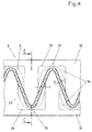
- FIGS. 4 to 6 show the preferred embodiment of the tool 3 shown to carry out the process.
- the basic structure of the Injection mold 3 from sawtooth-like profiles 30, 31 is the same as in FIGS. 1 to 3. However, the detection of the front edge area 18 of the bellows 6 not by protruding edges 15 on the saw teeth 4 and 5 reached, but the profiles 30, 31 are of the same height throughout Comb 32, but on their flanks 33 with exemptions 34 fitted.
- This type of profiles 30, 31 ensures a secure position individual folds 35, 36 of the bellows 6 to each other and the Front edges 19 of the bellows 6 can be securely grasped and pressed together are for the injection molding process.
- the exemptions 34 on the flanks 33 allow the bellows 6 during assembly of the Profiles 30, 31 can dodge and that only in a narrow area 18 of the front edges 19 of the bellows 6 is pressed together.
- the flanks 33 are provided with a to equip correspondingly low exemption 34.
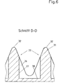
- the exemptions 34 as shown in Figures 4 and 6, at right angles have mutually facing surfaces 37, 38, since this makes use easier Tools for the formation of the exemptions 34 is possible.
- 4 is the compressed visible end face 12 of the bellows 6 is hatched drawn.
- the non-compressed part of the bellows 6 is dashed indicated.
- the exemptions 34 are with the dash-dotted line 39 marked.
- Figure 5 shows a section along the line C-C of Figure 4 below Omission of the upper profile 30. It is only the lower profile 31 is shown.
- the profile 31 has an equally high ridge 32 and is on its Flanks 33 with the exemption 34, with a narrow area the ends of the profile 31 is not covered by the exemption 34. This area serves to compress the front edges 19 of the bellows 6.
- FIG. 6 shows the profile 31 again in section, the shape of the preferred exemption 34 is visible.
Landscapes
- Chemical & Material Sciences (AREA)
- Chemical Kinetics & Catalysis (AREA)
- Engineering & Computer Science (AREA)
- Manufacturing & Machinery (AREA)
- Mechanical Engineering (AREA)
- Injection Moulding Of Plastics Or The Like (AREA)
- Moulds For Moulding Plastics Or The Like (AREA)
- Filtering Of Dispersed Particles In Gases (AREA)
Abstract
Description
- Fig. 1
- Die Seitenansicht eines Randabschnitts des Werkzeugprofils,
- Fig. 2:
- einen Schnitt durch das Profil gemäß Linie A-A der Fig. 1,
- Fig. 3:
- einen Schnitt gemäß Linie B-B in der Fig. 2,
- Fig. 4:
- eine Ausführungsform mit Freistellungen an den Profilflanken,
- Fig. 5:
- einen Schnitt gemäß Linie C-C der Fig. 4 und
- Fig. 6:
- einen Schnitt gemäß Linie D-D in der Figur 5.
Claims (5)
- Verfahren zur Herstellung einer Filterkassette mit Faltenbalg und Kunststoffrahmen, dadurch gekennzeichnet, daß der Faltenbalg (6) in ein Spritzgießwerkzeug (3) eingefügt und durch Spritzgießen mit dem Kunststoffrahmen (24) versehen wird, wobei die sich gegenüberliegenden Flächen des Werkzeugs (3) mindestens an ihren Randflächen (15) mit sägezahnartigen Profilen (1, 2; 30, 31) versehen sind, die ineinandergreifend die einzelnen Falten (22, 23; 35, 36) des Faltenbalgs (6) in einer definierten Lage zueinander halten und der Faltenbalg (6) in einem schmalen Bereich (18) seiner Stirnkanten (19) von den Profilen (1, 2; 30, 31) erfaßt und für den Spritzgießvorgang abdichtend zusammengepreßt wird.
- Werkzeug zur Durchführung des Verfahrens nach Anspruch 1, gekennzeichnet durch ein Spritzgießwerkzeug (3) mit einer Rahmenform mit einer Matritze und Patritze, dessen Flächen mit sägezahnartigen Profilen (1, 2; 30, 31) versehen sind, die ineinandergreifend die einzelnen Falten (22, 23; 35, 36) des Faltenbalgs (6)in einer definierten Lage halten und die im Bereich der Stirnkanten (19) des Faltenbalgs (6) bei geschlossenem Werkzeug (3) in einem Abstand (10) zueinander stehen, der ein sicheres Erfassen, Zusammenpressen und Abdichten der Stirnkanten (19) des Faltenbalgs (6) ergibt.
- Werkzeug nach Anspruch 2, dadurch gekennzeichnet, daß die Profile (1, 2) an ihren seitlichen Enden über die Kontur der Sägezähne (4, 5) hervorstehende Randflächen (15) haben, deren Oberflächen (27) parallel zu den Oberflächen (28) der Profile (1, 2) liegen und die den Stirnkantenbereich (18) des Faltenbalgs (6) zusammenpressen.
- Werkzeug nach Anspruch 2, dadurch gekennzeichnet, daß die Profile (30, 31) jeweils einen gleichhohen Kamm (32) haben und an ihren Flanken (33) mit Freistellungen (34) versehen sind, wobei die seitlichen Enden (39) der Flanken (3) von den Freistellungen (34) nicht erfaßt sind.
- Werkzeug nach Anspruch 4, dadurch gekennzeichnet, daß die Freistellungen (3, 4) im rechten Winkel zueinander stehende Flächen (37, 38) haben.
Applications Claiming Priority (2)
| Application Number | Priority Date | Filing Date | Title |
|---|---|---|---|
| DE19958344 | 1999-12-03 | ||
| DE19958344A DE19958344C2 (de) | 1999-12-03 | 1999-12-03 | Werkzeug zur Herstellung einer Filterkassette mit Faltenbalg und Kunststoffrahmen |
Publications (1)
| Publication Number | Publication Date |
|---|---|
| EP1106230A1 true EP1106230A1 (de) | 2001-06-13 |
Family
ID=7931316
Family Applications (1)
| Application Number | Title | Priority Date | Filing Date |
|---|---|---|---|
| EP00122660A Withdrawn EP1106230A1 (de) | 1999-12-03 | 2000-10-18 | Herstellung einer Filterkassette mit Faltenbalg und Werkzeug mit Sägezahnprofil |
Country Status (5)
| Country | Link |
|---|---|
| US (1) | US6582213B2 (de) |
| EP (1) | EP1106230A1 (de) |
| KR (1) | KR100402719B1 (de) |
| DE (1) | DE19958344C2 (de) |
| ZA (1) | ZA200007089B (de) |
Cited By (2)
| Publication number | Priority date | Publication date | Assignee | Title |
|---|---|---|---|---|
| EP1260340A1 (de) * | 2001-05-22 | 2002-11-27 | Carl Freudenberg KG | Filterkassette und Spritzgiesswerkzeug zur Herstellung des Filterkassettenrahmens |
| CN102814918A (zh) * | 2012-08-30 | 2012-12-12 | 芜湖毅昌科技有限公司 | 一种过滤网注塑工装及其注塑方法 |
Families Citing this family (6)
| Publication number | Priority date | Publication date | Assignee | Title |
|---|---|---|---|---|
| DE10062423C1 (de) * | 2000-12-14 | 2002-06-06 | Freudenberg Carl Kg | Spritzgießwerkzeug zur Herstellung von Kunststoffrahmen bei Filterkassetten |
| JP4670166B2 (ja) * | 2001-03-21 | 2011-04-13 | トヨタ紡織株式会社 | フィルタの製造方法 |
| US20050025848A1 (en) * | 2003-07-30 | 2005-02-03 | Ruey-Fa Huang | Air filter shaping mold |
| ITMI20071263A1 (it) * | 2007-06-22 | 2008-12-23 | Maurizio Ciocca | Impianto e metodo per la produzione di una cornice per mezzi di filtrazione dell'aria |
| DE102009056511A1 (de) * | 2009-12-02 | 2011-06-09 | Mann+Hummel Gmbh | Filterelement und Verfahren zum Herstellen eines Filterelements |
| DE102013010777A1 (de) | 2013-06-28 | 2014-12-31 | Carl Freudenberg Kg | Flächiges Medium mit einem Anbindeelement |
Citations (5)
| Publication number | Priority date | Publication date | Assignee | Title |
|---|---|---|---|---|
| JPS6041517A (ja) * | 1983-08-13 | 1985-03-05 | Toyo Roki Seizo Kk | エアクリ−ナエレメントの製造方法 |
| JPS63287522A (ja) * | 1987-05-19 | 1988-11-24 | Shuji Harada | エア−クリ−ナ−用ダストネツトの製造方法と成型金型 |
| DE3925511C1 (en) * | 1989-08-02 | 1990-08-09 | Helsa-Werke Helmut Sandler Gmbh & Co Kg, 8586 Gefrees, De | Low cost filter with good stability - filter element has zigzag folds and surrounding frame using 2 mould halves |
| DE19736267C1 (de) * | 1997-08-21 | 1998-12-03 | Freudenberg Carl Fa | Verfahren zur Herstellung eines Filtereinsatzes |
| DE19745919C1 (de) * | 1997-10-17 | 1999-08-12 | Minnesota Mining & Mfg | Spritzgußform zum Umspritzen von Kunststoff um ein Filtermaterial, Filter zum Filtern von Fluiden und Verfahren zum Herstellen eines derartigen Filters |
Family Cites Families (13)
| Publication number | Priority date | Publication date | Assignee | Title |
|---|---|---|---|---|
| US3183286A (en) * | 1961-07-31 | 1965-05-11 | American Air Filter Co | Method of making unit filter assemblies |
| DE7039288U (de) * | 1970-10-23 | 1971-03-25 | Eberwein H | Schuszwaffe |
| US4347208A (en) * | 1981-04-13 | 1982-08-31 | Amf Incorporated | Method of making filter cell having sealed periphery |
| AU540096B2 (en) * | 1982-08-04 | 1984-11-01 | Nippondenso Co. Ltd. | Filter device and manufacturing method |
| GB2162768B (en) * | 1984-08-06 | 1989-01-11 | Tilghman Wheelabrator Ltd | Filtering apparatus |
| DE8808632U1 (de) * | 1988-07-06 | 1988-09-01 | Ing. Walter Hengst GmbH & Co. KG, 48147 Münster | Luftfiltereinsatz mit angegossenem Tragrahmen |
| DE4002078C1 (de) * | 1990-01-25 | 1991-05-02 | Fa. Carl Freudenberg, 6940 Weinheim, De | |
| DE4039288C2 (de) * | 1990-12-08 | 1997-09-18 | Knecht Filterwerke Gmbh | Filtereinsatz für insbesondere Gasfilter |
| EP0523986A1 (de) * | 1991-07-17 | 1993-01-20 | Universal Filtration (Proprietary) Limited | Vorrichtung zur Herstellung eines Filterelements |
| DE4323522A1 (de) * | 1993-07-14 | 1995-01-19 | Knecht Filterwerke Gmbh | Filterelement aus zick-zack-förmig gefaltetem Filterbahnmaterial |
| JP3662092B2 (ja) * | 1997-03-21 | 2005-06-22 | 東洋▲ろ▼機製造株式会社 | フィルターエレメント及びその製造方法 |
| JPH1190150A (ja) * | 1997-09-22 | 1999-04-06 | Osaka Gas Co Ltd | フイルターの製造方法 |
| JP2001239121A (ja) * | 2000-03-02 | 2001-09-04 | Toyobo Co Ltd | フィルターユニットおよびその製造方法 |
-
1999
- 1999-12-03 DE DE19958344A patent/DE19958344C2/de not_active Expired - Fee Related
-
2000
- 2000-10-18 EP EP00122660A patent/EP1106230A1/de not_active Withdrawn
- 2000-11-30 ZA ZA200007089A patent/ZA200007089B/xx unknown
- 2000-12-01 US US09/728,234 patent/US6582213B2/en not_active Expired - Fee Related
- 2000-12-04 KR KR10-2000-0072904A patent/KR100402719B1/ko not_active Expired - Fee Related
Patent Citations (5)
| Publication number | Priority date | Publication date | Assignee | Title |
|---|---|---|---|---|
| JPS6041517A (ja) * | 1983-08-13 | 1985-03-05 | Toyo Roki Seizo Kk | エアクリ−ナエレメントの製造方法 |
| JPS63287522A (ja) * | 1987-05-19 | 1988-11-24 | Shuji Harada | エア−クリ−ナ−用ダストネツトの製造方法と成型金型 |
| DE3925511C1 (en) * | 1989-08-02 | 1990-08-09 | Helsa-Werke Helmut Sandler Gmbh & Co Kg, 8586 Gefrees, De | Low cost filter with good stability - filter element has zigzag folds and surrounding frame using 2 mould halves |
| DE19736267C1 (de) * | 1997-08-21 | 1998-12-03 | Freudenberg Carl Fa | Verfahren zur Herstellung eines Filtereinsatzes |
| DE19745919C1 (de) * | 1997-10-17 | 1999-08-12 | Minnesota Mining & Mfg | Spritzgußform zum Umspritzen von Kunststoff um ein Filtermaterial, Filter zum Filtern von Fluiden und Verfahren zum Herstellen eines derartigen Filters |
Non-Patent Citations (2)
| Title |
|---|
| PATENT ABSTRACTS OF JAPAN vol. 009, no. 171 (C - 291) 16 July 1985 (1985-07-16) * |
| PATENT ABSTRACTS OF JAPAN vol. 013, no. 111 (C - 577) 16 March 1989 (1989-03-16) * |
Cited By (2)
| Publication number | Priority date | Publication date | Assignee | Title |
|---|---|---|---|---|
| EP1260340A1 (de) * | 2001-05-22 | 2002-11-27 | Carl Freudenberg KG | Filterkassette und Spritzgiesswerkzeug zur Herstellung des Filterkassettenrahmens |
| CN102814918A (zh) * | 2012-08-30 | 2012-12-12 | 芜湖毅昌科技有限公司 | 一种过滤网注塑工装及其注塑方法 |
Also Published As
| Publication number | Publication date |
|---|---|
| DE19958344A1 (de) | 2001-08-16 |
| ZA200007089B (en) | 2001-06-20 |
| DE19958344C2 (de) | 2001-12-20 |
| US6582213B2 (en) | 2003-06-24 |
| US20010013670A1 (en) | 2001-08-16 |
| KR20010062108A (ko) | 2001-07-07 |
| KR100402719B1 (ko) | 2003-10-22 |
Similar Documents
| Publication | Publication Date | Title |
|---|---|---|
| EP0438639B1 (de) | Verfahren zur Herstellung eines als Faltenpack ausgebildeten Filtereinsatzes aus Vliesstoff | |
| DE4039288C2 (de) | Filtereinsatz für insbesondere Gasfilter | |
| DE2137309C3 (de) | Filter mit einem aus einem Zickzack förmig gefalteten, mit thermoplastischem Kunstharz imprägnierten Filterpapierstreifen bestehenden Faltblock | |
| DE2818713C2 (de) | Aus Kunststoffolie gebildeter Flachbeutel | |
| DE69412268T2 (de) | Filter zum filtrieren eines fluids | |
| DE2356028B2 (de) | Plane mit gelochtem verstaerkungsrand sowie verfahren zu deren herstellung | |
| DE60210237T2 (de) | Verfahren und Vorrichtung zur Herstellung von wellblechartig geformten Blechen und Vorrichtung zur Behandlung von Fluiden | |
| DE19941029C2 (de) | Filtereinsatz aus einem zickzackförmig gefalteten Faltenpack und Verfahren zu seiner Herstellung | |
| DE4227744A1 (de) | Zick-zack-förmig gefaltetes Filterbahnmaterial und daraus gefertigtes Filterelement | |
| DE19958344C2 (de) | Werkzeug zur Herstellung einer Filterkassette mit Faltenbalg und Kunststoffrahmen | |
| EP1797940A1 (de) | Filter | |
| DE69817748T2 (de) | Beutel mit komplementären profilverschlussstreifen sowie eine solche verschlussvorrichtung | |
| DE4445842A1 (de) | Als Faltenpack ausgebildeter Filtereinsatz aus Vliesstoff und Verfahren zu seiner Herstellung | |
| AT394342B (de) | Behaelterzuschnitt aus faltbarem flachmaterial | |
| EP2397211B1 (de) | Innenraumluftfilterelement, Filteraufnahme, Filteranordnung und Verfahren zum Herstellen des Innenraumluftfilterelements | |
| DE2610071A1 (de) | Verfahren zum herstellen endseitig versiegelter reissverschlusshaelften | |
| DE3643539C2 (de) | ||
| DE19503024C2 (de) | Luftfilter | |
| DE4323522A1 (de) | Filterelement aus zick-zack-förmig gefaltetem Filterbahnmaterial | |
| DE19731766B4 (de) | Flaches Plattenfilter aus zick-zack-förmig gefaltetem Filterbahnmaterial und flaches Filtergehäuse mit einem solchen Plattenfilter | |
| EP0401546A1 (de) | Packung für fliessfähige Stoffe und Verfahren zur Herstellung derselben | |
| DE10124846C1 (de) | Filterkassette und Spritzgiesswerkzeug zur Herstellung eines Kunststoffrahmens an einer Filterkassette und Filterkassette | |
| DE19824506C1 (de) | Filterelement und Verfahren zu seiner Herstellung | |
| DE3304471C2 (de) | Formgepreßte Leiste mit Randverstärkung sowie Formpreßwerkzeug zu ihrer Herstellung | |
| DE2131775C3 (de) | Verfahren zum Herstellen eines Reißverschlusses |
Legal Events
| Date | Code | Title | Description |
|---|---|---|---|
| PUAI | Public reference made under article 153(3) epc to a published international application that has entered the european phase |
Free format text: ORIGINAL CODE: 0009012 |
|
| 17P | Request for examination filed |
Effective date: 20010220 |
|
| AK | Designated contracting states |
Kind code of ref document: A1 Designated state(s): DE ES FR GB IT |
|
| AX | Request for extension of the european patent |
Free format text: AL;LT;LV;MK;RO;SI |
|
| RAP1 | Party data changed (applicant data changed or rights of an application transferred) |
Owner name: CARL FREUDENBERG KG |
|
| AKX | Designation fees paid |
Free format text: DE ES FR GB IT |
|
| 17Q | First examination report despatched |
Effective date: 20030320 |
|
| GRAP | Despatch of communication of intention to grant a patent |
Free format text: ORIGINAL CODE: EPIDOSNIGR1 |
|
| STAA | Information on the status of an ep patent application or granted ep patent |
Free format text: STATUS: THE APPLICATION IS DEEMED TO BE WITHDRAWN |
|
| 18D | Application deemed to be withdrawn |
Effective date: 20050322 |