EP1105234B1 - Verfahren und vorrichtung zum kontinuierlichen entgasen von schmelzflüssigen metallen - Google Patents
Verfahren und vorrichtung zum kontinuierlichen entgasen von schmelzflüssigen metallen Download PDFInfo
- Publication number
- EP1105234B1 EP1105234B1 EP99944261A EP99944261A EP1105234B1 EP 1105234 B1 EP1105234 B1 EP 1105234B1 EP 99944261 A EP99944261 A EP 99944261A EP 99944261 A EP99944261 A EP 99944261A EP 1105234 B1 EP1105234 B1 EP 1105234B1
- Authority
- EP
- European Patent Office
- Prior art keywords
- chamber
- degassing
- casting
- bath
- pipe
- Prior art date
- Legal status (The legal status is an assumption and is not a legal conclusion. Google has not performed a legal analysis and makes no representation as to the accuracy of the status listed.)
- Expired - Lifetime
Links
- 239000002184 metal Substances 0.000 title claims description 62
- 229910052751 metal Inorganic materials 0.000 title claims description 62
- 238000007872 degassing Methods 0.000 title claims description 28
- 238000000034 method Methods 0.000 title claims description 21
- 150000002739 metals Chemical class 0.000 title claims description 7
- 238000005266 casting Methods 0.000 claims description 34
- 238000010438 heat treatment Methods 0.000 claims description 7
- RYGMFSIKBFXOCR-UHFFFAOYSA-N Copper Chemical compound [Cu] RYGMFSIKBFXOCR-UHFFFAOYSA-N 0.000 claims description 6
- 229910052802 copper Inorganic materials 0.000 claims description 6
- 239000010949 copper Substances 0.000 claims description 6
- 230000005484 gravity Effects 0.000 claims description 2
- 230000001939 inductive effect Effects 0.000 claims description 2
- 239000001257 hydrogen Substances 0.000 description 5
- 229910052739 hydrogen Inorganic materials 0.000 description 5
- 229910000831 Steel Inorganic materials 0.000 description 4
- 239000007788 liquid Substances 0.000 description 4
- 239000010959 steel Substances 0.000 description 4
- 238000009489 vacuum treatment Methods 0.000 description 4
- UFHFLCQGNIYNRP-UHFFFAOYSA-N Hydrogen Chemical compound [H][H] UFHFLCQGNIYNRP-UHFFFAOYSA-N 0.000 description 3
- 238000005516 engineering process Methods 0.000 description 3
- 239000007789 gas Substances 0.000 description 3
- 230000001105 regulatory effect Effects 0.000 description 3
- 238000003860 storage Methods 0.000 description 3
- XKRFYHLGVUSROY-UHFFFAOYSA-N Argon Chemical compound [Ar] XKRFYHLGVUSROY-UHFFFAOYSA-N 0.000 description 2
- QVGXLLKOCUKJST-UHFFFAOYSA-N atomic oxygen Chemical compound [O] QVGXLLKOCUKJST-UHFFFAOYSA-N 0.000 description 2
- 230000001419 dependent effect Effects 0.000 description 2
- 238000011161 development Methods 0.000 description 2
- 230000018109 developmental process Effects 0.000 description 2
- 150000002431 hydrogen Chemical class 0.000 description 2
- 230000001965 increasing effect Effects 0.000 description 2
- 229910001338 liquidmetal Inorganic materials 0.000 description 2
- 238000004519 manufacturing process Methods 0.000 description 2
- 239000000155 melt Substances 0.000 description 2
- 239000001301 oxygen Substances 0.000 description 2
- 229910052760 oxygen Inorganic materials 0.000 description 2
- 238000013019 agitation Methods 0.000 description 1
- 229910052786 argon Inorganic materials 0.000 description 1
- 230000033228 biological regulation Effects 0.000 description 1
- 238000006243 chemical reaction Methods 0.000 description 1
- 238000009749 continuous casting Methods 0.000 description 1
- 230000007423 decrease Effects 0.000 description 1
- 230000007547 defect Effects 0.000 description 1
- 238000002844 melting Methods 0.000 description 1
- 230000008018 melting Effects 0.000 description 1
- 238000005272 metallurgy Methods 0.000 description 1
- 238000010327 methods by industry Methods 0.000 description 1
- 239000000203 mixture Substances 0.000 description 1
- 239000012768 molten material Substances 0.000 description 1
- 238000010926 purge Methods 0.000 description 1
- 238000000926 separation method Methods 0.000 description 1
- 239000002893 slag Substances 0.000 description 1
- 230000006641 stabilisation Effects 0.000 description 1
- 238000011105 stabilization Methods 0.000 description 1
- 230000003068 static effect Effects 0.000 description 1
- 238000011144 upstream manufacturing Methods 0.000 description 1
Images

Classifications
-
- B—PERFORMING OPERATIONS; TRANSPORTING
- B22—CASTING; POWDER METALLURGY
- B22D—CASTING OF METALS; CASTING OF OTHER SUBSTANCES BY THE SAME PROCESSES OR DEVICES
- B22D11/00—Continuous casting of metals, i.e. casting in indefinite lengths
- B22D11/10—Supplying or treating molten metal
- B22D11/11—Treating the molten metal
- B22D11/113—Treating the molten metal by vacuum treating
-
- C—CHEMISTRY; METALLURGY
- C21—METALLURGY OF IRON
- C21C—PROCESSING OF PIG-IRON, e.g. REFINING, MANUFACTURE OF WROUGHT-IRON OR STEEL; TREATMENT IN MOLTEN STATE OF FERROUS ALLOYS
- C21C7/00—Treating molten ferrous alloys, e.g. steel, not covered by groups C21C1/00 - C21C5/00
- C21C7/10—Handling in a vacuum
-
- C—CHEMISTRY; METALLURGY
- C22—METALLURGY; FERROUS OR NON-FERROUS ALLOYS; TREATMENT OF ALLOYS OR NON-FERROUS METALS
- C22B—PRODUCTION AND REFINING OF METALS; PRETREATMENT OF RAW MATERIALS
- C22B9/00—General processes of refining or remelting of metals; Apparatus for electroslag or arc remelting of metals
- C22B9/04—Refining by applying a vacuum
Definitions
- the invention relates to an apparatus and a method according to the preambles of claims 1 and 6.
- the so-called secondary metallurgy is the degassing of Metal melting basically under the keyword vacuum treatment known. This is a post-treatment of molten metal under greatly reduced pressure understood on the Insight is based on the fact that when the external pressure is lowered, the pressure in the Metal melt dissolved gases, especially hydrogen, escape. In the case of partial degassing that comes into consideration here becomes only part of the liquid melt at a time exposed to vacuum, either by vacuum circulation degassing or a vacuum lifter degassing.
- a preferred field of application of the methods presented is the production of oxygen-free copper (OF copper), in addition to low oxygen levels in the order of magnitude from 1 to 3 ppm also typically low hydrogen contents must be reached below 1 ppm.
- This takes advantage of that the hydrogen solubility in copper with falling Pressure decreases and therefore the one normally dissolved in copper Escape hydrogen from the metal under vacuum conditions can without increasing the oxygen content again.
- This The device has a supplied molten liquid Containers containing metals and one for degassing Vacuum chamber, in which an inflow for the molten First chamber containing metals protrudes a riser pipe, the upper end of which opens into the vacuum chamber, the Bottom has a drain opening connected to a downpipe is its lower end forming an outlet opening into a second chamber, designed as a casting chamber, into an outlet nozzle opens and is characterized in that the riser pipe and the downpipe are provided with a heater.
- the first and the second chamber are preferably spatially located with each other and have a dam that the Divides chambers in the lower area into two bath chambers, the Riser pipe and the down pipe in different areas below the upper edge of the dam.
- a dam that the Divides chambers in the lower area into two bath chambers, the Riser pipe and the down pipe in different areas below the upper edge of the dam.
- the riser pipe and the down pipe are preferably each parallel arranged vertically to each other.
- the task related to the procedure is determined by the measures solved according to claim 6, wherein the molten metal from a first chamber via a riser pipe with one below the bath level lying inlet opening in a as a degassing room serving vacuum chamber transferred and from there due to gravity into a downpipe with a lower outlet opening, which is preferably lies below the bath level in the casting chamber, in the casting chamber is discharged.
- This process technology has the Advantage that the molten metal, which transfers into the casting chamber is previously complete during the previous run of the Vacuum chamber has been degassed. A mix of already degassed molten metal with an untreated molten metal is thus avoided.
- the bath level in the first chamber and the casting chamber in different height levels.
- the riser pipe and the downpipe is a connection between the two chambers created according to the type of communicating tubes works, according to the height difference between the higher bath level in the first chamber and the bath level in a metal melt flow is maintained in the casting chamber.
- the molten metal can continuously or from the casting chamber be drained discontinuously.
- the first and the second chamber spatially connected and in lower area divided into two bath chambers by a dam.
- the bathroom mirrors are located in the first and second chamber below the top edge of the dam, the metal melt from the first chamber via the riser pipe into the vacuum chamber and from there through the downpipe into the casting chamber.
- the vacuum chamber e.g. in the event of a pump defect, or even in cases where degassing is not required the bathroom mirror is set so that it is above the edge of the said dam lies, so that in the first and the second chamber forms a common continuous bathroom mirror and that molten metal bypassing the vacuum chamber directly into the casting chamber.
- the degassing rate is very dependent on the temperature, which is why according to a further embodiment of the invention the molten metal is heated inductively, which makes it possible to control the degassing.
- the length of stay the molten metal in the vacuum chamber over the Pressure regulated in this vacuum chamber is a further embodiment of the invention.
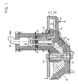
- the system shown has a pouring chamber 10 into which the liquid metal continuously from an upstream Storage oven is filled. Runs out of this pouring chamber 10 the molten metal through an inductor channel or Inductor channels 11 in the first chamber 20, in which a vertical arranged riser 15 protrudes so that the riser with its lower opening is below the bathroom mirror.
- the Riser pipe 15 and the down pipe 16, which in a casting chamber 13th protrudes and its lower opening also under the one there Bathroom mirrors are in the form of connecting pieces of the floor Vacuum chamber 17 formed by means of a nozzle 18 a pump can be evacuated.
- the casting chamber 13 and the first Chamber 20 are separated from one another by a dam 12.
- the bath level in the pouring chamber 10 or the first Chamber 20 can be set between the limits 21 and 22 the molten metal as shown in Fig. 1 of the first chamber 20 only via the riser pipe Vacuum chamber 17 and the downpipe get into the casting chamber 13.
- In the entry area there is still a Inductor, by means of which the flowing molten metal is heated can be. With this inductor is an ideal means to control the degassing, which is strongly temperature-dependent is.
- Burner 19 provided which the riser pipe 15 and the down pipe 16 heat. Compared to inductive heating, this has Burner heating has the advantage that it preheats the Entire chamber including the risers allowed.
- the Casting chamber 13 also has a nozzle 14, through which the molten Metal can be drained.
- the degassed metal To protect against air ingress, the casting chamber 13 is over a weir 24 separated from the rest of the furnace atmosphere, so that the Casting chamber is hermetically sealed to the outside. The weir ends with its lower edge below the bathroom mirror in the Casting chamber.
- the device according to the invention works as follows:
- the pouring chamber 10 is filled with molten material via an inlet Metal continuously filled, with the bathroom mirror between the boundary lines 21 and 22.
- the Vacuum chamber 17 set a negative pressure, which causes the molten metal rises over the riser pipe 15, in the vacuum chamber 17 is degassed.
- the molten metal flows through the downpipe 16 beyond the dam 12 into the casting chamber 13 as long as the bath level there is below the level the bath level of the pouring chamber.
- the burners 19 are operated for adequate temperature control to care.
- the level of the bath level 27 in the Container 22 corresponds to the static pressure in the Vacuum chamber 17.
- the bath level in the first chamber 20 is adjusted so that the Dam 12 is flooded so that the molten metal can get directly into the casting chamber 13.
Landscapes
- Chemical & Material Sciences (AREA)
- Engineering & Computer Science (AREA)
- Materials Engineering (AREA)
- Metallurgy (AREA)
- Organic Chemistry (AREA)
- Mechanical Engineering (AREA)
- Manufacturing & Machinery (AREA)
- Manufacture And Refinement Of Metals (AREA)
- Continuous Casting (AREA)
- Treatment Of Steel In Its Molten State (AREA)
- Furnace Details (AREA)
Applications Claiming Priority (3)
| Application Number | Priority Date | Filing Date | Title |
|---|---|---|---|
| DE19831675 | 1998-07-15 | ||
| DE19831675 | 1998-07-15 | ||
| PCT/DE1999/002028 WO2000003821A1 (de) | 1998-07-15 | 1999-07-01 | Verfahren und vorrichtung zum kontinuierlichen entgasen von schmelzflüssigen metallen |
Publications (2)
| Publication Number | Publication Date |
|---|---|
| EP1105234A1 EP1105234A1 (de) | 2001-06-13 |
| EP1105234B1 true EP1105234B1 (de) | 2002-05-29 |
Family
ID=7874091
Family Applications (1)
| Application Number | Title | Priority Date | Filing Date |
|---|---|---|---|
| EP99944261A Expired - Lifetime EP1105234B1 (de) | 1998-07-15 | 1999-07-01 | Verfahren und vorrichtung zum kontinuierlichen entgasen von schmelzflüssigen metallen |
Country Status (5)
| Country | Link |
|---|---|
| US (1) | US6454829B1 (enExample) |
| EP (1) | EP1105234B1 (enExample) |
| JP (1) | JP2002520162A (enExample) |
| DE (1) | DE59901564D1 (enExample) |
| WO (1) | WO2000003821A1 (enExample) |
Cited By (1)
| Publication number | Priority date | Publication date | Assignee | Title |
|---|---|---|---|---|
| AT515235A1 (de) * | 2013-12-30 | 2015-07-15 | Inteco Special Melting Technologies Gmbh | Verfahren und Anordnung zum Vakuumblockguss |
Families Citing this family (4)
| Publication number | Priority date | Publication date | Assignee | Title |
|---|---|---|---|---|
| CN101279360B (zh) * | 2008-05-15 | 2010-09-29 | 天津钢管集团股份有限公司 | 直径为Ф350~Ф400mm低合金钢连铸圆管坯的生产方法 |
| CN106480257B (zh) * | 2015-08-29 | 2018-05-22 | 党祎贤 | 泵阀真空除气装置 |
| CN108480575A (zh) * | 2018-04-10 | 2018-09-04 | 佛山市三水万瑞达环保科技有限公司 | 一种熔液除气装置 |
| CN116752001B (zh) * | 2023-06-19 | 2025-10-17 | 云南爱家铝业有限公司 | 一种高强度铝合金材料的制备工艺 |
Family Cites Families (15)
| Publication number | Priority date | Publication date | Assignee | Title |
|---|---|---|---|---|
| BE556194A (enExample) | ||||
| DE1103950B (de) | 1956-02-21 | 1961-04-06 | Hoerder Huettenunion Ag | Einrichtung zum fortlaufenden Entgasen von Metall-, insbesondere Stahlschmelzen |
| US3310850A (en) | 1963-12-13 | 1967-03-28 | Rheinstahl Huettenwerke Ag | Method and apparatus for degassing and casting metals in a vacuum |
| US3402921A (en) | 1965-08-30 | 1968-09-24 | Phelps Dodge Corp | Apparatus and method of making apparatus for vacuum purification of metals |
| DE2058669A1 (de) | 1970-11-28 | 1972-05-31 | Kocks Gmbh Friedrich | Vakuumbehandlung von Metallschmelzen |
| US3706449A (en) * | 1971-04-27 | 1972-12-19 | Pullman Inc | Vacuum degassing unit |
| CH606452A5 (en) | 1975-01-10 | 1978-10-31 | Inst Litya Akademii Nauk Uk Ss | Vacuum degassing liq metals before casting |
| JPS5499729A (en) | 1978-01-25 | 1979-08-06 | Mitsubishi Heavy Ind Ltd | Continuously vacuum treating method for molten steel |
| JPS5910448A (ja) | 1982-07-12 | 1984-01-19 | Kawasaki Steel Corp | 連続鋳造における鋳型への給湯方法 |
| EP0134336A1 (en) * | 1983-08-16 | 1985-03-20 | William Lyon Sherwood | Continuous steelmaking and casting |
| JPS6156760A (ja) | 1984-08-27 | 1986-03-22 | Nippon Kokan Kk <Nkk> | 連続鋳造用タンデイツシユ |
| JPS61166912A (ja) | 1985-01-18 | 1986-07-28 | Osaka Shinku Kiki Seisakusho:Kk | 連続脱ガス方法とその装置 |
| JPH0620618B2 (ja) | 1985-03-26 | 1994-03-23 | 日立電線株式会社 | 連続鋳造方法及びその装置 |
| JPS6440153A (en) | 1987-08-01 | 1989-02-10 | Kawasaki Steel Co | Metallurgical treating apparatus in tundish for continuous casting |
| JPH0830222B2 (ja) * | 1987-11-30 | 1996-03-27 | 日立電線株式会社 | 溶銅の連続真空脱ガス装置 |
-
1999
- 1999-07-01 DE DE59901564T patent/DE59901564D1/de not_active Expired - Lifetime
- 1999-07-01 JP JP2000559951A patent/JP2002520162A/ja active Pending
- 1999-07-01 WO PCT/DE1999/002028 patent/WO2000003821A1/de not_active Ceased
- 1999-07-01 US US09/719,819 patent/US6454829B1/en not_active Expired - Fee Related
- 1999-07-01 EP EP99944261A patent/EP1105234B1/de not_active Expired - Lifetime
Cited By (1)
| Publication number | Priority date | Publication date | Assignee | Title |
|---|---|---|---|---|
| AT515235A1 (de) * | 2013-12-30 | 2015-07-15 | Inteco Special Melting Technologies Gmbh | Verfahren und Anordnung zum Vakuumblockguss |
Also Published As
| Publication number | Publication date |
|---|---|
| EP1105234A1 (de) | 2001-06-13 |
| DE59901564D1 (de) | 2002-07-04 |
| US6454829B1 (en) | 2002-09-24 |
| JP2002520162A (ja) | 2002-07-09 |
| WO2000003821A1 (de) | 2000-01-27 |
Similar Documents
| Publication | Publication Date | Title |
|---|---|---|
| DE2842505B1 (de) | Verfahren zum chargenweisen Ablassen einer Borosilikatglasschmelze aus einem keramischen Glasschmelzofen mit beheiztem Bodenauslauf und Einrichtung zur Durchfuehrung des Verfahrens | |
| DE2723601A1 (de) | Verfahren zum abschrecken von aus oefen kommender schlacke | |
| DE1508166C2 (de) | Verfahren und Vorrichtung zum Fördern von Metallschmelzen, insbesondere Stahlschmelzen | |
| DE69422641T2 (de) | Vakuumschlackenentfernung eines metallurgischer schmelzofen | |
| EP1105234B1 (de) | Verfahren und vorrichtung zum kontinuierlichen entgasen von schmelzflüssigen metallen | |
| DE69428123T2 (de) | Vorrichtung und Verfahren zum Raffinieren einer Metallschmelze | |
| DE1912936A1 (de) | Verfahren und Vorrichtung zum Reinigen und Vakuumentgasen von schmelzfluessigen Metallen | |
| EP1301642A1 (de) | Verfahren und vorrichtung zur verminderung des sauerstoffgehaltes einer kupferschmelze | |
| DE1458812A1 (de) | Vorrichtung zum Vakuumbehandeln von Schmelzen,insbesondere Stahlschmelzen,und Verfahren zu ihrem Betrieb | |
| DE1960283A1 (de) | Vakuumentgasungsvorrichtung fuer die Verwendung beim Stranggiessen von Metallen und Verfahren zum Stranggiessen von schmelzfluessigem Metall,waehrend es einer Vakuumentgasung unterworfen ist | |
| DE29812571U1 (de) | Vorrichtung zum kontinuierlichen Entgasen von schmelzflüssigen Metallen | |
| EP2106454B1 (de) | Vorrichtung und verfahren zum behandeln von werkblei | |
| DE3721945C2 (enExample) | ||
| EP0221329A1 (de) | Verfahren und Vorrichtung zum Abschrecken von Glühgut | |
| DE2526815A1 (de) | Verfahren zum automatischen entschlacken eines kupolofens | |
| DE2501603C3 (enExample) | ||
| DE1558412A1 (de) | Verfahren und Vorrichtung zum Einschmelzen von Metall | |
| DE19811722C1 (de) | Vorrichtung zum Vakuumfrischen von Metall-, insbesondere Stahlschmelzen | |
| WO2007073823A1 (de) | Giessanlage insbesondere für aluminium bzw. aluminiumlegierungen sowie verfahren zum betrieb der giessanlage | |
| DE3621789C1 (en) | Installation for tempering metal parts in a continuous operation | |
| AT365239B (de) | Verfahren zum behandeln einer stahlschmelze und vorrichtung zur durchfuehrung desselben | |
| DE1169476B (de) | Verfahren und Vorrichtung zum Vakuum-entgasen und -giessen von fluessigen Metallen, insbesondere Stahl | |
| DE2058669A1 (de) | Vakuumbehandlung von Metallschmelzen | |
| WO2005123304A2 (de) | Giessverfahren und giessanlage für aluminium bzw. aluminiumlegierungen | |
| DE1458812C (de) | Vorrichtung zum kontinuierlichen Vakuumbehandeln von Metallschmelzen, ins besondere Stahlschmelzen, und Verfahren zu ihrem Betrieb |
Legal Events
| Date | Code | Title | Description |
|---|---|---|---|
| PUAI | Public reference made under article 153(3) epc to a published international application that has entered the european phase |
Free format text: ORIGINAL CODE: 0009012 |
|
| 17P | Request for examination filed |
Effective date: 20001215 |
|
| AK | Designated contracting states |
Kind code of ref document: A1 Designated state(s): AT BE CH CY DE DK ES FI FR GB GR IE IT LI LU MC NL PT SE |
|
| GRAG | Despatch of communication of intention to grant |
Free format text: ORIGINAL CODE: EPIDOS AGRA |
|
| GRAG | Despatch of communication of intention to grant |
Free format text: ORIGINAL CODE: EPIDOS AGRA |
|
| GRAH | Despatch of communication of intention to grant a patent |
Free format text: ORIGINAL CODE: EPIDOS IGRA |
|
| 17Q | First examination report despatched |
Effective date: 20011025 |
|
| GRAH | Despatch of communication of intention to grant a patent |
Free format text: ORIGINAL CODE: EPIDOS IGRA |
|
| GRAA | (expected) grant |
Free format text: ORIGINAL CODE: 0009210 |
|
| AK | Designated contracting states |
Kind code of ref document: B1 Designated state(s): BE DE GR IT |
|
| REG | Reference to a national code |
Ref country code: IE Ref legal event code: FG4D Free format text: GERMAN |
|
| REF | Corresponds to: |
Ref document number: 59901564 Country of ref document: DE Date of ref document: 20020704 |
|
| REG | Reference to a national code |
Ref country code: GR Ref legal event code: EP Ref document number: 20020402645 Country of ref document: GR |
|
| REG | Reference to a national code |
Ref country code: IE Ref legal event code: FD4D Ref document number: 1105234E Country of ref document: IE |
|
| PLBE | No opposition filed within time limit |
Free format text: ORIGINAL CODE: 0009261 |
|
| STAA | Information on the status of an ep patent application or granted ep patent |
Free format text: STATUS: NO OPPOSITION FILED WITHIN TIME LIMIT |
|
| 26N | No opposition filed |
Effective date: 20030303 |
|
| PGFP | Annual fee paid to national office [announced via postgrant information from national office to epo] |
Ref country code: BE Payment date: 20060822 Year of fee payment: 8 |
|
| BERE | Be: lapsed |
Owner name: INDUSTRIEOFEN UND GIESSEREI-ANLAGEN G.M.B.H. & CO. Effective date: 20070731 |
|
| PG25 | Lapsed in a contracting state [announced via postgrant information from national office to epo] |
Ref country code: BE Free format text: LAPSE BECAUSE OF NON-PAYMENT OF DUE FEES Effective date: 20070731 |
|
| PGFP | Annual fee paid to national office [announced via postgrant information from national office to epo] |
Ref country code: IT Payment date: 20080724 Year of fee payment: 10 |
|
| PGFP | Annual fee paid to national office [announced via postgrant information from national office to epo] |
Ref country code: GR Payment date: 20080724 Year of fee payment: 10 |
|
| PG25 | Lapsed in a contracting state [announced via postgrant information from national office to epo] |
Ref country code: GR Free format text: LAPSE BECAUSE OF NON-PAYMENT OF DUE FEES Effective date: 20100204 |
|
| PGFP | Annual fee paid to national office [announced via postgrant information from national office to epo] |
Ref country code: DE Payment date: 20100511 Year of fee payment: 12 |
|
| PG25 | Lapsed in a contracting state [announced via postgrant information from national office to epo] |
Ref country code: IT Free format text: LAPSE BECAUSE OF NON-PAYMENT OF DUE FEES Effective date: 20090701 |
|
| PG25 | Lapsed in a contracting state [announced via postgrant information from national office to epo] |
Ref country code: DE Free format text: LAPSE BECAUSE OF NON-PAYMENT OF DUE FEES Effective date: 20120201 |
|
| REG | Reference to a national code |
Ref country code: DE Ref legal event code: R119 Ref document number: 59901564 Country of ref document: DE Effective date: 20120201 |