EP1103989A2 - Gleichstromelektromagnet für Schaltgerät - Google Patents
Gleichstromelektromagnet für Schaltgerät Download PDFInfo
- Publication number
- EP1103989A2 EP1103989A2 EP00403306A EP00403306A EP1103989A2 EP 1103989 A2 EP1103989 A2 EP 1103989A2 EP 00403306 A EP00403306 A EP 00403306A EP 00403306 A EP00403306 A EP 00403306A EP 1103989 A2 EP1103989 A2 EP 1103989A2
- Authority
- EP
- European Patent Office
- Prior art keywords
- electromagnet according
- magnetic circuit
- sheets
- electromagnet
- cut
- Prior art date
- Legal status (The legal status is an assumption and is not a legal conclusion. Google has not performed a legal analysis and makes no representation as to the accuracy of the status listed.)
- Granted
Links
- 230000006698 induction Effects 0.000 claims abstract description 4
- 239000011324 bead Substances 0.000 claims description 6
- 239000000654 additive Substances 0.000 claims description 5
- 238000010276 construction Methods 0.000 description 5
- 230000000996 additive effect Effects 0.000 description 1
- 230000000295 complement effect Effects 0.000 description 1
- 238000010586 diagram Methods 0.000 description 1
- 238000005516 engineering process Methods 0.000 description 1
- 230000005284 excitation Effects 0.000 description 1
- 230000004907 flux Effects 0.000 description 1
Images


Classifications
-
- H—ELECTRICITY
- H01—ELECTRIC ELEMENTS
- H01F—MAGNETS; INDUCTANCES; TRANSFORMERS; SELECTION OF MATERIALS FOR THEIR MAGNETIC PROPERTIES
- H01F7/00—Magnets
- H01F7/06—Electromagnets; Actuators including electromagnets
- H01F7/08—Electromagnets; Actuators including electromagnets with armatures
- H01F7/16—Rectilinearly-movable armatures
- H01F7/1607—Armatures entering the winding
- H01F7/1623—Armatures having T-form
-
- H—ELECTRICITY
- H01—ELECTRIC ELEMENTS
- H01F—MAGNETS; INDUCTANCES; TRANSFORMERS; SELECTION OF MATERIALS FOR THEIR MAGNETIC PROPERTIES
- H01F7/00—Magnets
- H01F7/06—Electromagnets; Actuators including electromagnets
- H01F7/08—Electromagnets; Actuators including electromagnets with armatures
- H01F7/081—Magnetic constructions
Definitions
- the present invention relates to a direct current electromagnet for switch device such as contactor or contactor-circuit breaker, comprising a induction coil cooperating with a magnetic circuit consisting of a fixed part and a moving part.
- Direct current electromagnets are used in devices such as contactors or contactors.
- the mobile magnetic circuit also called movable armature
- the fixed magnetic circuit (also called breech) is often associated with minus a permanent magnet which polarizes the magnetic circuit and obtains low consumption.
- Each of the permanent magnets is mounted between a room inner pole, relatively close to the coil, and an outer pole piece, laterally farther from the coil.
- the mobile magnetic circuit is generally constituted, as in the document FR 2 586 324, by a core on which are fitted plates of polar. With this type of construction it is difficult to respect the coasts and the geometry.
- the object of the invention is to provide a direct current electromagnet whose magnetic circuit is obtained by stacking cut sheets, some of which have a low height and are assembled to each other.
- This technology allows to produce parts with good geometric precision and in particular allows to realize a mobile magnetic circuit with polar expansions joined to the core without flow discontinuity.
- the parts of the fixed magnetic circuit can have a strong thickness (this being formed by the sum of the thicknesses of the assembled sheets).
- the electromagnet according to the invention is characterized in that at least one parts of the magnetic circuit consists of a stack of cut sheets and assembled to each other and having a variable height, in small places, stronger in terms of mechanical assembly means.
- the cut sheets have a variable height between 2 and 5 mm in some places.
- the part of the magnetic circuit formed of cut and stacked sheets is a movable frame with core and openings polar, these having a larger surface than the section of the core, the assembly consisting of H-shaped cut sheets and, to achieve the polar openings, of I-shaped cut sheets completing the branches of the core sheets.
- the induction coil is wound on a spool holder consisting of two parts joined to each other so as to house the mobile magnetic circuit.
- control electromagnet marked E in its together is mounted in a switchgear in which poles are arranged cutoff P on current lines C1-C2 which can be connected by terminals B1-B2 to electrical cables.
- This control electromagnet E is of the direct current and it is supplied from terminals A1 and A2. It is used to activate the poles in response to excitation or de-excitation of its coil. It is controlled by a control module M and a manual control member T.
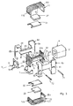
- the electromagnet E consists of a coil 4 and a magnetic circuit which channels the magnetic flux and consists of a fixed part and a mobile part.
- the fixed magnetic circuit or yoke consists of two pole pieces interior 31 and 32 which are relatively close to the coil and two parts outer poles 11 and 12 which are further laterally from the coil.
- the mobile magnetic circuit 5 consists of a magnetic core 53 of general parallelepiped shape combining a first polar development 51 and a second pole position 52. This circuit 5 slides along the axis V-V 'in a bore of the support 8 of the coil.
- the two polar flourishings 51 and 52 extend perpendicular to V-V 'and form planar polar faces 51a-51b on the one hand, 52a on the other hand. They have the shape of rectangular plates, the surface of openings being greater than the section of the core 53.
- the movable frame 5 is subjected to a return spring 6 which tends to move to a rest position.
- the two outer pole pieces 11 and 12 of the fixed magnetic circuit have each a U-shaped profile and are mounted in opposition and spaced one of the other so as to provide a space in which the coil 4 and its support 8, the inner pole pieces 31 and 32, the magnets 21-22 and the armature mobile 5.
- Each outer pole piece 11 or 12 has a extending core parallel to the axis V-V 'and two wings extending perpendicular to this axis V-V'.
- the inner pole pieces 31-32 are planar and extend parallel to the axis V-V '.
- the electromagnet E is polarized and has two permanent magnets 21 and 22 each having a parallelepiped shape and each inserted between a pole piece outer 11 or 12 and an inner pole piece 31 or 32 respectively.
- the face facing the axis V-V 'of each core of an outer pole piece 11 or 12 is adjacent to a pole face of the permanent magnet 21 or 22 respectively.
- the other polar face of each of the magnets 21 or 22, facing the axis V-V ', is adjacent to the inner pole piece 31 or 32 respectively.
- the pole shoe 51 of the frame 5 is housed in two air gaps each extending between the end face of one of the pole pieces 31 or 32 and the folded wing of the adjacent outer pole piece 11 or 12. It moves in this air gap from a first position located against the pole pieces 31-32, to a second position against the cylinder head 11-12.
- the other development 52 of the frame 5 extends outside the folded wings of the outer pole pieces 11 or 12.
- Each of the outer pole pieces 11 or 12 is produced from a stacking of cut sheets 111 or 121 in a U shape.
- the cut sheets are joined by rivets 112 or 122 and by weld beads such as 113 which extend over the entire thickness of the stack.
- the mobile magnetic circuit 5 is obtained by stacking sheets cut 531 in H shape and cut sheet 511, 521 in I shape, these last completing the branches of the core 531 sheets so as to achieve the polar openings 51, 52.
- the polar openings 51 and 52 are therefore produced by the branches of H 531 sheets and by complementary sheets 511 or 521 in an I shape.
- the sheets 531, 511 and 521 are joined to each other by riveting 532, 512, 522 and by weld beads 523 which extend over the entire thickness sheets.
- the weld beads can be made by laser.
- the cut sheets 111, 112, 531, 521, 512 have a variable height H which is in some places between 2 and 5 mm. Height H means the distance between the edges measured in the plane of the cut sheets. The height is higher at level of rivets 112, 122, 512, 522. Parts 11 and 12 have beads at the assembly rivets 112, 122, 512, 522.
- the coil 4 is wound on a coil support 8 consisting of two parts 8a, 8b assembled to each other so as to form a central hub 83 in which houses the central core 53 of the mobile magnetic circuit 5. These two parts 8a and 8b are joined according to a joint plane passing through V-V '.
- the hub 83 is connected to two cages 84 and 85 in which the pole shoes 51 and 52 move.
- the movable frame 5 is provided with two guide pins 71 and 72 which cross the polar openings 51 and 52 and slide, in a passing plane by V-V ', in the guide slots 81 and 82 of the coil holder 8.
- the movable frame 5 actuates, when it is moved in translation, a lever L mounted pivoting about an axis O and which then activates the poles P.
- One of the pole shoes 52 is provided laterally with fingers 9a used to activate the pivoting lever L for operating the poles when the armature mobile 5 is requested.
- This polar development is also provided at the front a finger 9b used to activate additives mounted on the switch device.
- This lever control finger 9a and additive control finger 9b are formed on a clip 9 which is fixed to the front of the pole shoe 52.
- the finger 9b of the additives passes through an opening in the housing and is moved in translation parallel to V-V '.
- the movable armature 5 When the coil 4 is energized, the movable armature 5 is biased towards the working position and a closed or substantially closed magnetic field passing through the core 53, the flourishing 52, the outer pole pieces 11-12, flourishing 51 is created. This magnetic field does not pass through the magnets permanent 21-22.
- the return spring moves the armature movable 5 to a rest position in which the opening 51 is in contact with pole pieces 31-32 so that the magnetic circuit closes through permanent magnets 21-22.
Landscapes
- Physics & Mathematics (AREA)
- Electromagnetism (AREA)
- Engineering & Computer Science (AREA)
- Power Engineering (AREA)
- Electromagnets (AREA)
- Relay Circuits (AREA)
Applications Claiming Priority (2)
| Application Number | Priority Date | Filing Date | Title |
|---|---|---|---|
| FR9915174A FR2801721B1 (fr) | 1999-11-29 | 1999-11-29 | Electroaimant a courant continu pour appareil interrupteur |
| FR9915174 | 1999-11-29 |
Publications (3)
| Publication Number | Publication Date |
|---|---|
| EP1103989A2 true EP1103989A2 (de) | 2001-05-30 |
| EP1103989A3 EP1103989A3 (de) | 2002-05-08 |
| EP1103989B1 EP1103989B1 (de) | 2008-03-12 |
Family
ID=9552786
Family Applications (1)
| Application Number | Title | Priority Date | Filing Date |
|---|---|---|---|
| EP20000403306 Expired - Lifetime EP1103989B1 (de) | 1999-11-29 | 2000-11-23 | Gleichstromelektromagnet für Schaltgerät |
Country Status (4)
| Country | Link |
|---|---|
| EP (1) | EP1103989B1 (de) |
| DE (1) | DE60038274T2 (de) |
| ES (1) | ES2300250T3 (de) |
| FR (1) | FR2801721B1 (de) |
Cited By (2)
| Publication number | Priority date | Publication date | Assignee | Title |
|---|---|---|---|---|
| WO2003030188A1 (de) * | 2001-09-24 | 2003-04-10 | Abb Patent Gmbh | Elektromagnetischer aktuator |
| EP2204825A3 (de) * | 2008-12-31 | 2014-11-19 | LS Industrial Systems Co., Ltd | Monostabiler Dauermagnetaktuator mit laminiertem Stahlkern |
Family Cites Families (5)
| Publication number | Priority date | Publication date | Assignee | Title |
|---|---|---|---|---|
| US3058039A (en) * | 1957-06-24 | 1962-10-09 | Gen Controls Co | Laminated magnetic structure, and process for making same |
| EP0174239B1 (de) * | 1984-08-20 | 1988-06-01 | Telemecanique | Polarisierter Elektromagnet in symmetrischer Ausführung |
| EP0216943B1 (de) * | 1985-08-06 | 1989-11-02 | Ibm Deutschland Gmbh | Elektromagnetische Betätigungsvorrichtung, insbesondere für Druckhammerantriebe |
| JP3171751B2 (ja) * | 1994-04-05 | 2001-06-04 | 東芝テック株式会社 | ダイヤフラム式電磁ポンプ |
| JPH08138509A (ja) * | 1994-11-02 | 1996-05-31 | Fuji Electric Co Ltd | 直流電磁接触器 |
-
1999
- 1999-11-29 FR FR9915174A patent/FR2801721B1/fr not_active Expired - Lifetime
-
2000
- 2000-11-23 DE DE2000638274 patent/DE60038274T2/de not_active Expired - Lifetime
- 2000-11-23 ES ES00403306T patent/ES2300250T3/es not_active Expired - Lifetime
- 2000-11-23 EP EP20000403306 patent/EP1103989B1/de not_active Expired - Lifetime
Cited By (2)
| Publication number | Priority date | Publication date | Assignee | Title |
|---|---|---|---|---|
| WO2003030188A1 (de) * | 2001-09-24 | 2003-04-10 | Abb Patent Gmbh | Elektromagnetischer aktuator |
| EP2204825A3 (de) * | 2008-12-31 | 2014-11-19 | LS Industrial Systems Co., Ltd | Monostabiler Dauermagnetaktuator mit laminiertem Stahlkern |
Also Published As
| Publication number | Publication date |
|---|---|
| EP1103989A3 (de) | 2002-05-08 |
| FR2801721A1 (fr) | 2001-06-01 |
| EP1103989B1 (de) | 2008-03-12 |
| FR2801721B1 (fr) | 2002-01-18 |
| DE60038274D1 (de) | 2008-04-24 |
| ES2300250T3 (es) | 2008-06-16 |
| DE60038274T2 (de) | 2009-03-19 |
Similar Documents
| Publication | Publication Date | Title |
|---|---|---|
| EP0146421B1 (de) | Elektromagnet mit Jochen und einem Anker mit einem Permanentmagneten, der an seinen Polflächen über die sich quer zur Bewegungsrichtung erstreckende Magnetachse hinausragende Polstücke aufweist | |
| EP2037476B1 (de) | Elektromagnetisches Stellglied und Schaltgerät, das mit einem solchen elektromagnetischen Stellglied ausgestattet ist | |
| EP1811536B1 (de) | Magnetisches Stellglied mit Permanentmagnet mit reduziertem Volumen | |
| EP2126951B1 (de) | Hybrider elektromagnetischer aktor | |
| RU2465674C1 (ru) | Контактное переключающее устройство и электромагнитное реле | |
| EP0026695B1 (de) | Elektromagnet mit beweglichem permanentmagnetischem Teil, insbesondere für Kontaktvorrichtung | |
| FR2841683A1 (fr) | Actionneur magnetique | |
| EP1103989A2 (de) | Gleichstromelektromagnet für Schaltgerät | |
| FR3060194A1 (fr) | Dispositif de coupure electrique equipe d'un module magnetique pour le soufflage de l'arc electrique | |
| JP2009009710A (ja) | 電磁リレー | |
| EP1576627B1 (de) | Elektromagnetische ventilbetätigungsvorrichtung mit einem permanentmagneten | |
| WO2010018030A1 (fr) | Actionneur electromagnetique hybride a bobine fixe | |
| EP1655755B1 (de) | Elektromagnetischer Betätiger mit beweglicher Spule | |
| FR2955696A1 (fr) | Commutateur electrique coulissant | |
| FR2686189A1 (fr) | Perfectionnement aux appareils interrupteurs a commande electromagnetique et manuelle, tels que relais, contacteurs ou contacteurs jour-nuit. | |
| EP3939151B1 (de) | Elektromagnetische vorrichtung | |
| EP1568858B1 (de) | Elektromagnetische Ventilsteuerungseinrichtung für Brennkraftmaschine | |
| EP0551777A1 (de) | Schaltgeräte für elektromagnetische und manuelle Betätigung | |
| FR3050568A1 (fr) | Actionneur bistable pour un relais electromagnetique polarise | |
| FR2722609A1 (fr) | Disjoncteur electrique a actionneur electromagnetique pour calibres eleves | |
| FR2485798A1 (fr) | Actionneur electromagnetique | |
| EP0905735B1 (de) | Schutzschalter mit elektromagnetischen Auslöser mit Antrieb für einen beweglichen und gabelförmigen Kontakt | |
| CH668498A5 (fr) | Electro-aimant a courant continu a mouvement de translation. | |
| EP1376639B1 (de) | Elektromagnetischer Auslöser mit linear bewegtem Tauchkolben | |
| EP1594149B1 (de) | Magnetischer Überstromauslöser mit Torsionsfeder |
Legal Events
| Date | Code | Title | Description |
|---|---|---|---|
| PUAI | Public reference made under article 153(3) epc to a published international application that has entered the european phase |
Free format text: ORIGINAL CODE: 0009012 |
|
| AK | Designated contracting states |
Kind code of ref document: A2 Designated state(s): AT BE CH CY DE DK ES FI FR GB GR IE IT LI LU MC NL PT SE TR |
|
| AX | Request for extension of the european patent |
Free format text: AL;LT;LV;MK;RO;SI |
|
| PUAL | Search report despatched |
Free format text: ORIGINAL CODE: 0009013 |
|
| AK | Designated contracting states |
Kind code of ref document: A3 Designated state(s): AT BE CH CY DE DK ES FI FR GB GR IE IT LI LU MC NL PT SE TR |
|
| AX | Request for extension of the european patent |
Free format text: AL;LT;LV;MK;RO;SI |
|
| 17P | Request for examination filed |
Effective date: 20020603 |
|
| RAP1 | Party data changed (applicant data changed or rights of an application transferred) |
Owner name: SCHNEIDER ELECTRONIC INDUSTRIES SAS |
|
| RAP1 | Party data changed (applicant data changed or rights of an application transferred) |
Owner name: SCHNEIDER ELECTRIC INDUSTRIES SAS |
|
| AKX | Designation fees paid |
Designated state(s): DE ES GB SE |
|
| 17Q | First examination report despatched |
Effective date: 20070411 |
|
| GRAP | Despatch of communication of intention to grant a patent |
Free format text: ORIGINAL CODE: EPIDOSNIGR1 |
|
| GRAS | Grant fee paid |
Free format text: ORIGINAL CODE: EPIDOSNIGR3 |
|
| GRAA | (expected) grant |
Free format text: ORIGINAL CODE: 0009210 |
|
| AK | Designated contracting states |
Kind code of ref document: B1 Designated state(s): DE ES GB SE |
|
| REG | Reference to a national code |
Ref country code: GB Ref legal event code: FG4D Free format text: NOT ENGLISH |
|
| REF | Corresponds to: |
Ref document number: 60038274 Country of ref document: DE Date of ref document: 20080424 Kind code of ref document: P |
|
| REG | Reference to a national code |
Ref country code: ES Ref legal event code: FG2A Ref document number: 2300250 Country of ref document: ES Kind code of ref document: T3 |
|
| PLBE | No opposition filed within time limit |
Free format text: ORIGINAL CODE: 0009261 |
|
| STAA | Information on the status of an ep patent application or granted ep patent |
Free format text: STATUS: NO OPPOSITION FILED WITHIN TIME LIMIT |
|
| 26N | No opposition filed |
Effective date: 20081215 |
|
| PGFP | Annual fee paid to national office [announced via postgrant information from national office to epo] |
Ref country code: ES Payment date: 20091123 Year of fee payment: 10 Ref country code: SE Payment date: 20091021 Year of fee payment: 10 |
|
| PGFP | Annual fee paid to national office [announced via postgrant information from national office to epo] |
Ref country code: GB Payment date: 20091110 Year of fee payment: 10 |
|
| REG | Reference to a national code |
Ref country code: SE Ref legal event code: EUG |
|
| GBPC | Gb: european patent ceased through non-payment of renewal fee |
Effective date: 20101123 |
|
| PG25 | Lapsed in a contracting state [announced via postgrant information from national office to epo] |
Ref country code: SE Free format text: LAPSE BECAUSE OF NON-PAYMENT OF DUE FEES Effective date: 20101124 |
|
| PG25 | Lapsed in a contracting state [announced via postgrant information from national office to epo] |
Ref country code: GB Free format text: LAPSE BECAUSE OF NON-PAYMENT OF DUE FEES Effective date: 20101123 |
|
| REG | Reference to a national code |
Ref country code: ES Ref legal event code: FD2A Effective date: 20120110 |
|
| PG25 | Lapsed in a contracting state [announced via postgrant information from national office to epo] |
Ref country code: ES Free format text: LAPSE BECAUSE OF NON-PAYMENT OF DUE FEES Effective date: 20101124 |
|
| REG | Reference to a national code |
Ref country code: DE Ref legal event code: R084 Ref document number: 60038274 Country of ref document: DE |
|
| PGFP | Annual fee paid to national office [announced via postgrant information from national office to epo] |
Ref country code: DE Payment date: 20191008 Year of fee payment: 20 |
|
| REG | Reference to a national code |
Ref country code: DE Ref legal event code: R071 Ref document number: 60038274 Country of ref document: DE |