EP1594149B1 - Magnetischer Überstromauslöser mit Torsionsfeder - Google Patents
Magnetischer Überstromauslöser mit Torsionsfeder Download PDFInfo
- Publication number
- EP1594149B1 EP1594149B1 EP04360047A EP04360047A EP1594149B1 EP 1594149 B1 EP1594149 B1 EP 1594149B1 EP 04360047 A EP04360047 A EP 04360047A EP 04360047 A EP04360047 A EP 04360047A EP 1594149 B1 EP1594149 B1 EP 1594149B1
- Authority
- EP
- European Patent Office
- Prior art keywords
- spring
- magnetic
- stops
- striker
- subassembly according
- Prior art date
- Legal status (The legal status is an assumption and is not a legal conclusion. Google has not performed a legal analysis and makes no representation as to the accuracy of the status listed.)
- Expired - Lifetime
Links
- 238000006073 displacement reaction Methods 0.000 claims description 17
- 230000001939 inductive effect Effects 0.000 claims 1
- 230000007423 decrease Effects 0.000 description 6
- 238000009527 percussion Methods 0.000 description 4
- 238000010304 firing Methods 0.000 description 3
- 230000035945 sensitivity Effects 0.000 description 3
- 238000006243 chemical reaction Methods 0.000 description 2
- 238000013459 approach Methods 0.000 description 1
- 230000006835 compression Effects 0.000 description 1
- 238000007906 compression Methods 0.000 description 1
- 238000010586 diagram Methods 0.000 description 1
- 230000000694 effects Effects 0.000 description 1
- 239000000696 magnetic material Substances 0.000 description 1
- 230000036316 preload Effects 0.000 description 1
- 229920002994 synthetic fiber Polymers 0.000 description 1
- 238000003466 welding Methods 0.000 description 1
Images


Classifications
-
- H—ELECTRICITY
- H01—ELECTRIC ELEMENTS
- H01H—ELECTRIC SWITCHES; RELAYS; SELECTORS; EMERGENCY PROTECTIVE DEVICES
- H01H71/00—Details of the protective switches or relays covered by groups H01H73/00 - H01H83/00
- H01H71/10—Operating or release mechanisms
- H01H71/12—Automatic release mechanisms with or without manual release
- H01H71/24—Electromagnetic mechanisms
Definitions
- the present invention relates to a magnetic subassembly for electric apparatus of the circuit breaker type, conventionally composed of an inductor coil associated with a magnetic yoke and a magnetic core movable in translation against a spring, said core driving with him. a striker for triggering a mechanical lock controlling the position of the movable contact relative to the fixed contact.
- the magnetic subsets or triggers have the function of separating the respectively mobile and fixed contacts in the event of a short circuit in the circuit in which they are connected.
- the sudden overcurrent through the coil saturates the magnetic circuit, causing the displacement of the mobile core which actually fills the air gap that separates it from the rest of the magnetic yoke.
- a return spring is interposed between a fixed element relative to the housing of the device and the movable core, so that it returns to the rest position (restoring the gap) when the circuit is cut.
- the stiffness of the spring is chosen according to the category to which belongs the circuit breaker, in particular manifested by the existence of curve B, C and D of "sensitivity" which define the interval, expressed as a function of the rated current of the circuit breaker , in which it must trigger. This stiffness obviously also depends on the size of the circuit breaker.
- the chosen spring is obviously provided with a stiffness making it able to oppose the magnetic force generated by the currents of this order in the coil.
- This type of spring necessarily having a correspondingly high stiffness, obviously has a response time all the greater as said stiffness is important.
- the magnetic subassemblies must imperatively cause their spacing as quickly as possible. It should be noted that the increase in the response time resulting from the stiffness and the nature of the springs used, especially for circuit breakers of high caliber and whose sensitivity corresponds to curve D, does not go in this direction.
- the objective of the present invention is therefore to provide a configuration such that the resistive energy opposed by the spring decreases as the displacement of the moving assembly constituted by the core and its striker during a short circuit.
- the magnetic subassembly of the invention is characterized in that said spring is a torsion spring with a spiral central portion and two end arms deploying in V against abutments, the spring and said stops being driven by a relative movement such that the distance between the stops and the central portion of the spring in the direction of translation increases as the gap between the core and the yoke is closed.
- the torsion spring has a symmetry with respect to the axis of displacement of the moving assembly.
- the mobile assembly moves by sliding and is guided in at least one fixed slide relative to the housing.
- the spring has indeed an action on the movable assembly that could disturb the direction of movement, and therefore the path of the striker, if the guide was the only effect of magnetic forces on the displacement of the core.
- the moving assembly consists of a magnetic pallet and a superimposed striker.
- the pallet or magnetic core must be imperatively made of a magnetic material that is not necessarily the most suitable for the striker, for economic or even mechanical reasons according to the tasks entrusted to it.
- the sliding of the movable magnetic pallet / striker assembly is carried out by guiding said assembly in slides made symmetrically in lateral cheeks disposed in the housing on either side of the magnetic subassembly.
- the guide function is thus provided by pieces forming said cheeks, which may be made of a synthetic material, for example molded, to which it is easy and inexpensive to give a complex shape for carrying out various functions.
- said cheeks indeed in particular also serve to house the magnetic subassembly.
- each slide may consist of a wall parallel to the axis of movement of said moving assembly, on either side of which slides respectively projecting laterally from the striker and a face of the magnetic pallet oriented opposite said tabs.
- the two components of the moving assembly therefore participate in the guidance in translation.
- the magnetic subassembly of the invention in addition to such a coil, preferably comprises a trapezoidal magnetic paddle cooperating with a gap of the yoke also trapezoidal shape.
- the stops of the spring consist of tabs each providing a C-section housing at a portion of an end arm of the spring, said C-section being heard perpendicular to the direction of movement of the moving assembly .
- the spiral portion of the spring is driven by the moving assembly, and the stops of the spring are fixed relative to the housing of the device.
- the central portion of the spring is wound around the top portion of a barrel constituting a protuberance of the striker passing through and protruding from an orifice formed in the magnetic pallet, a portion of said striker having a surface of percussion oriented perpendicular to the movement standing in front of the front edge of said pallet.
- the mechanical relations, both with the spring and with the mechanical lock operating the trigger, are supported by the striker.
- the sole purpose of the magnetic pallet is to drive the firing pin when it undergoes sufficient Laplace forces to successfully resist the resistive force of the spring.
- the spring can be fixed to the housing of the device, and the stops of the spring are integral with the moving assembly.
- the appended figures 2 to 9 represent a version of the invention in which the torsion spring is integral with the moving element.
- the torsion spring (1) has a central wound portion (2) and end arms deployed in V (3) and (3 ').
- This spring (1) is driven by the shaft (4) of a movable assembly comprising firstly the striker (5) and secondly the core / the magnetic pallet (6).
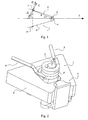
- the resistance opposed by the spring (1) to the displacement of the moving assembly, and in particular of the shaft (4) on the axis x can be calculated as follows:
- the spring (1) exerts on the stop (7) a force F 1 .
- the force seen by the stop is F 2 , according to the scheme.
- F 3 is in fact the reaction of the stop (7) on the arm (3) of the spring (1), taking into account the friction. It is therefore separated from an angle ⁇ of the reaction - F 2 of the stop (7) on the arm (3) of the spring (1), in the absence of friction.
- ⁇ being the angular variation of the angle existing between the direction of displacement x and the line joining the stop (7) to the center of the shaft (4) and k, the stiffness of the spring (1).
- the movable pallet (6) associated with the striker (5) and the spring (1) is shown in the enlarged context of its association with the magnetic yoke, itself formed of two symmetrical parts (8, 8 ').
- This yoke comprises a first gap (9) in which the pallet (6) moves, and a second gap (10) for receiving the movable contact (not shown).
- the figure 4 shows, in more detail, the striker (5) which is in the form of a sliding carriage with a central shaft (4), lugs (11, 11 ') provided for sliding in slides (see ci -after), said carriage having, at the front in the direction of displacement in the event of a short circuit, a protuberance provided with a planar frontal surface of percussion (12).
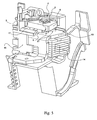
- the figure 5 shows the moving element consisting of the pallet (6), the firing pin (5) and the spring (1), arranged in a situation that is to say located with respect to other elements of the magnetic subassembly, is provided for its immobilization in the housing.
- said moving element overcomes the coil (13) of said magnetic subassembly, which in fact forms three quarters of a turn made by a magnetic sheet folded around a core (14) conventionally constituted of a stack of sheets.
- the coil (13) / core (14) assembly is inserted into a lateral cheek (15) which participates in the positioning of a number of elements of the circuit breaker.
- the coil (13) and the core (14) are masked by one of the parts (8 ') of the yoke, which is not shown here.
- This second cheek (15 ') however appears on the figure 6 , in which substantially all of the magnetic subassembly, except the spring (1) and the upper parts of the moving assembly, namely the shaft (4) and the front projection with its percussion surface (12) , is hidden.
- their upper part constitutes a window (16) allowing the displacement of the moving equipment, and contributing at least partially to its guidance in the direction of the arrow (F).
- the spring (1) whose ends (3, 3 ') appear, is surmounted by a kind of cover or hood (18) which caps the upper parts of the cheeks (15, 15').
- This cover (18) which allows a premounting of the spring (1), appears in figure 8 .
- It contains the stops (7, 7 ') which determine in particular the preload of the torsion spring (1), and therefore allow to adapt to the size and sensitivity of the circuit breaker.
- the stops (7, 7 ') contain a housing C for the ends (3, 3') of the spring (1).
Landscapes
- Physics & Mathematics (AREA)
- Electromagnetism (AREA)
- Electromagnets (AREA)
- Breakers (AREA)
- Reciprocating, Oscillating Or Vibrating Motors (AREA)
- Emergency Protection Circuit Devices (AREA)
- Driving Mechanisms And Operating Circuits Of Arc-Extinguishing High-Tension Switches (AREA)
- Transformers For Measuring Instruments (AREA)
Claims (11)
- Magnetischer Überstromauslöser für ein elektrisches Gerät der Art Unterbrecher, der aus einer Feldspule besteht, die einem Magnetjoch (8, 8') und einer Einheit aus beweglichem Kern (6) / Schlagstift (5), die gegen eine Feder (1) beweglich verschoben werden kann, zugeordnet ist, dadurch gekennzeichnet, dass die Feder eine Torsionsfeder ist und einen spiralförmigen Mittelbereich (2) und zwei Enden (3, 3') aufweist, die sich V-förmig ausbreiten und gegen Anschläge (7, 7') aufliegen, wobei die Feder (1) und die Anschläge (7, 7') durch eine relative Bewegung agieren, so dass der Abstand zwischen den Anschlägen (7, 7') und dem Mittelbereich (2) der Feder (1) in Richtung der Verschiebung nach und nach mit dem Schließen des Spalts (9), der zwischen dem Kern (6) und dem Joch (8, 8') angeordnet ist, größer wird.
- Magnetischer Überstromauslöser gemäß dem vorausgegangenen Anspruch, dadurch gekennzeichnet, dass die Torsionsfeder (1) bezogen auf die Verschiebungsachse der beweglichen Einheit (5, 6) Symmetrie aufweist.
- Magnetischer Überstromauslöser gemäß einem der vorausgegangenen Ansprüche, dadurch gekennzeichnet, dass die bewegliche Einheit (5, 6) durch Gleiten verschiebbar ist und in wenigstens einer Gleitschiene geführt wird, die bezogen auf das Gehäuse feststehend ist.
- Magnetischer Überstromauslöser gemäß einem der vorausgegangenen Ansprüche, dadurch gekennzeichnet, dass die bewegliche Einheit (5, 6) aus einem Magnetanker (6) und einem Schlagstift (5) gebildet ist, die übereinander liegen.
- Magnetischer Überstromauslöser gemäß dem vorausgegangenen Anspruch, dadurch gekennzeichnet, dass das Gleiten der beweglichen Einheit Magnetanker (6) / Schlagstift (5) durch Führen der Einheit in Gleitschienen bewirkt wird, die symmetrisch in den Seitenbacken (15) vorgesehen sind, die feststehend in dem Gehäuse auf beiden Seiten des magnetischen Überstromauslösers angeordnet sind.
- Magnetischer Überstromauslöser gemäß dem vorausgegangenen Anspruch, dadurch gekennzeichnet, dass jede Gleitschiene aus einer Wand (17, 17') gebildet ist, die parallel zur Verschiebungsachse der beweglichen Einheit (5, 6) ist, wobei auf beiden Seiten dieser jeweils Laschen (11, 11') gleiten, die seitlich über den Schlagstift (5) und eine Seite des Magnetankers (6), die bezüglich der Laschen (11, 11') ausgerichtet sind, überstehen.
- Magnetischer Überstromauslöser gemäß einem der Ansprüche 4 bis 6, dadurch gekennzeichnet, dass der Anker (6) trapezförmig ist und mit einem Spalt (9) des Jochs (8, 8') zusammenwirkt, der ebenfalls trapezförmig ist.
- Magnetischer Überstromauslöser gemäß einem der vorausgegangenen Ansprüche, dadurch gekennzeichnet, dass die Anschläge (7, 7') der Feder aus Laschen gebildet sind, die jeweils einen Sitz mit C-förmigem Querschnitt für einen Teil eines Arms (3, 3') der Feder (1) vorsehen, wobei der C-förmige Querschnitt senkrecht in Verschiebungsrichtung der beweglichen Einheit (5, 6) ist.
- Magnetischer Überstromauslöser gemäß einem der vorausgegangenen Ansprüche, dadurch gekennzeichnet, dass der spiralförmige Abschnitt (2) der Feder (1) durch die bewegliche Einheit (5, 6) mitgeführt wird und die Anschläge (7, 7') der Feder (1) bezogen auf des Gehäuse des Geräts feststehend sind.
- Magnetischer Überstromauslöser gemäß dem vorausgegangenen Anspruch, dadurch gekennzeichnet, dass der Mittelbereich (2) der Feder (1) um den oberen Teil eines Schaftes (4) gerollt ist, der einen Überstand des Schlagstiftes (5) bildet, der durch eine Öffnung geht und über diese hinausgeht, die in dem Magnetanker (6) vorgesehen ist, wobei sich ein Bereich des Schlagstifts (5), der mit einer Schlagoberfläche ausgerüstet ist, die senkrecht zur Verschiebung ausgerichtet ist, sich vor der Vorderkante des Ankers (6) aufrichtet.
- Magnetischer Überstromauslöser gemäß einem der Ansprüche 1 bis 8, dadurch gekennzeichnet, dass die Feder (1) an dem Gehäuse des Geräts befestigt ist, und die Anschläge (7, 7') der Feder (1) mit der beweglichen Einheit (5, 6) fest verbunden sind.
Priority Applications (8)
| Application Number | Priority Date | Filing Date | Title |
|---|---|---|---|
| AT04360047T ATE415697T1 (de) | 2004-05-06 | 2004-05-06 | Magnetischer überstromauslöser mit torsionsfeder |
| EP04360047A EP1594149B1 (de) | 2004-05-06 | 2004-05-06 | Magnetischer Überstromauslöser mit Torsionsfeder |
| ES04360047T ES2318255T3 (es) | 2004-05-06 | 2004-05-06 | Subconjunto magnetico con muelle de torsion. |
| DE602004017961T DE602004017961D1 (de) | 2004-05-06 | 2004-05-06 | Magnetischer Überstromauslöser mit Torsionsfeder |
| SI200431040T SI1594149T1 (sl) | 2004-05-06 | 2004-05-06 | Magnetni podsklop s torzijsko vzmetjo |
| PCT/FR2005/001137 WO2005122202A1 (fr) | 2004-05-06 | 2005-05-06 | Sous-ensemble magnetique a ressort de torsion |
| BRPI0509831-9A BRPI0509831B1 (pt) | 2004-05-06 | 2005-05-06 | "magnetic subcontractor for electric type of circuit breaker" |
| CN2005800207256A CN1998058B (zh) | 2004-05-06 | 2005-05-06 | 具有扭矩弹簧的磁性子部件 |
Applications Claiming Priority (1)
| Application Number | Priority Date | Filing Date | Title |
|---|---|---|---|
| EP04360047A EP1594149B1 (de) | 2004-05-06 | 2004-05-06 | Magnetischer Überstromauslöser mit Torsionsfeder |
Publications (2)
| Publication Number | Publication Date |
|---|---|
| EP1594149A1 EP1594149A1 (de) | 2005-11-09 |
| EP1594149B1 true EP1594149B1 (de) | 2008-11-26 |
Family
ID=34931771
Family Applications (1)
| Application Number | Title | Priority Date | Filing Date |
|---|---|---|---|
| EP04360047A Expired - Lifetime EP1594149B1 (de) | 2004-05-06 | 2004-05-06 | Magnetischer Überstromauslöser mit Torsionsfeder |
Country Status (8)
| Country | Link |
|---|---|
| EP (1) | EP1594149B1 (de) |
| CN (1) | CN1998058B (de) |
| AT (1) | ATE415697T1 (de) |
| BR (1) | BRPI0509831B1 (de) |
| DE (1) | DE602004017961D1 (de) |
| ES (1) | ES2318255T3 (de) |
| SI (1) | SI1594149T1 (de) |
| WO (1) | WO2005122202A1 (de) |
Family Cites Families (5)
| Publication number | Priority date | Publication date | Assignee | Title |
|---|---|---|---|---|
| CH577748A5 (de) * | 1973-07-31 | 1976-07-15 | Ellenberger & Poensgen | |
| FR2447601A1 (fr) * | 1979-01-23 | 1980-08-22 | Legrand Sa | Relais d'intensite |
| KR100568906B1 (ko) * | 1997-09-18 | 2006-04-10 | 이튼 일렉트릭 비 브이 | 전자기 액츄에이터 |
| DE19946206A1 (de) * | 1999-09-27 | 2000-11-23 | Siemens Ag | Überstromauslöser |
| DE60201183T2 (de) * | 2002-06-17 | 2005-10-13 | Hager Electro S.A. | Elektromagnetischer Auslöser mit linear bewegtem Tauchkolben |
-
2004
- 2004-05-06 AT AT04360047T patent/ATE415697T1/de active
- 2004-05-06 ES ES04360047T patent/ES2318255T3/es not_active Expired - Lifetime
- 2004-05-06 SI SI200431040T patent/SI1594149T1/sl unknown
- 2004-05-06 EP EP04360047A patent/EP1594149B1/de not_active Expired - Lifetime
- 2004-05-06 DE DE602004017961T patent/DE602004017961D1/de not_active Expired - Lifetime
-
2005
- 2005-05-06 BR BRPI0509831-9A patent/BRPI0509831B1/pt not_active IP Right Cessation
- 2005-05-06 CN CN2005800207256A patent/CN1998058B/zh not_active Expired - Fee Related
- 2005-05-06 WO PCT/FR2005/001137 patent/WO2005122202A1/fr not_active Ceased
Also Published As
| Publication number | Publication date |
|---|---|
| BRPI0509831B1 (pt) | 2017-11-28 |
| CN1998058A (zh) | 2007-07-11 |
| CN1998058B (zh) | 2010-11-03 |
| ATE415697T1 (de) | 2008-12-15 |
| BRPI0509831A (pt) | 2007-10-16 |
| DE602004017961D1 (de) | 2009-01-08 |
| SI1594149T1 (sl) | 2009-04-30 |
| WO2005122202A1 (fr) | 2005-12-22 |
| ES2318255T3 (es) | 2009-05-01 |
| EP1594149A1 (de) | 2005-11-09 |
Similar Documents
| Publication | Publication Date | Title |
|---|---|---|
| EP0620580B1 (de) | Hilfsauslöser für Schutzschalter | |
| EP1080286B1 (de) | Elektronisches schloss mit mechanischer kupplung | |
| EP2816582A1 (de) | Auslöser und Herstellungsverfahren eines solchen Auslösers | |
| EP2458607A1 (de) | Verriegelungsvorrichtung zur Sicherung des Zugangs zur Kabeldose einer Stromzelle, und Stromzelle, die eine solche Vorrichtung enthält | |
| EP0696041B1 (de) | Schutzschalter | |
| EP1873807A1 (de) | Elektrische Schutzeinrichtung, die von einer Zusatzsteuervorrichtung gesteuert wird | |
| EP1594149B1 (de) | Magnetischer Überstromauslöser mit Torsionsfeder | |
| EP2456021A1 (de) | Stromsteckdose mit seitlichen verschiebbaren Balken | |
| EP2377139B1 (de) | Vorrichtung zur fernbetätigung und damit versehener schutzschalter | |
| EP2733719A1 (de) | Hilfsauslöser zur Auslösung eines Überlastschalters | |
| EP2359380B1 (de) | Mechanismus zur ansteuerung des steuerknüppels einer fernsteuerungseinheit und einheit damit | |
| FR2489586A1 (fr) | Interrupteur rotatif a enclenchement magnetique | |
| EP1818959A1 (de) | Elektrische Schaltvorrichtung mit verstärkten elektrischen Kontakten | |
| EP0018553B1 (de) | Modulschutzschalter | |
| EP0693765B1 (de) | Elektromagnetischer Auslöser für einen Niederspannungsschutzschalter | |
| FR2722609A1 (fr) | Disjoncteur electrique a actionneur electromagnetique pour calibres eleves | |
| FR2859816A1 (fr) | Dispositif de coupure de courant electrique a discrimination complete d'etats | |
| EP0996959B1 (de) | Elektrischer leistungsschalter für elektrische anlagen mit niederwechselspannung | |
| EP1583130B1 (de) | Magnetische Untereinheit für ein elektrisches Schaltgerät | |
| FR2984391A1 (fr) | Actionneur electrique pour ouvrant | |
| EP0054499B1 (de) | Schalter mit Trennung des Nulleiters | |
| EP1650780B1 (de) | Elektromechanischer Auslöser und elektronisches Schutzgerät mit letzterem | |
| FR2760892A1 (fr) | Coupe-batterie bi-stable a verrouillage mecanique | |
| EP3134910B1 (de) | Vorrichtung mit beweglichem kontakt ohne leitfähige litze | |
| EP3161850B1 (de) | Thermisch-magnetischer auslösungsmechanismus |
Legal Events
| Date | Code | Title | Description |
|---|---|---|---|
| PUAI | Public reference made under article 153(3) epc to a published international application that has entered the european phase |
Free format text: ORIGINAL CODE: 0009012 |
|
| AK | Designated contracting states |
Kind code of ref document: A1 Designated state(s): AT BE BG CH CY CZ DE DK EE ES FI FR GB GR HU IE IT LI LU MC NL PL PT RO SE SI SK TR |
|
| AX | Request for extension of the european patent |
Extension state: AL HR LT LV MK |
|
| 17P | Request for examination filed |
Effective date: 20060201 |
|
| AKX | Designation fees paid |
Designated state(s): AT BE BG CH CY CZ DE DK EE ES FI FR GB GR HU IE IT LI LU MC NL PL PT RO SE SI SK TR |
|
| 17Q | First examination report despatched |
Effective date: 20070124 |
|
| GRAP | Despatch of communication of intention to grant a patent |
Free format text: ORIGINAL CODE: EPIDOSNIGR1 |
|
| GRAS | Grant fee paid |
Free format text: ORIGINAL CODE: EPIDOSNIGR3 |
|
| GRAA | (expected) grant |
Free format text: ORIGINAL CODE: 0009210 |
|
| AK | Designated contracting states |
Kind code of ref document: B1 Designated state(s): AT BE BG CH CY CZ DE DK EE ES FI FR GB GR HU IE IT LI LU MC NL PL PT RO SE SI SK TR |
|
| REG | Reference to a national code |
Ref country code: GB Ref legal event code: FG4D Free format text: NOT ENGLISH |
|
| REG | Reference to a national code |
Ref country code: CH Ref legal event code: EP |
|
| REG | Reference to a national code |
Ref country code: IE Ref legal event code: FG4D Free format text: LANGUAGE OF EP DOCUMENT: FRENCH |
|
| REF | Corresponds to: |
Ref document number: 602004017961 Country of ref document: DE Date of ref document: 20090108 Kind code of ref document: P |
|
| REG | Reference to a national code |
Ref country code: ES Ref legal event code: FG2A Ref document number: 2318255 Country of ref document: ES Kind code of ref document: T3 |
|
| NLV1 | Nl: lapsed or annulled due to failure to fulfill the requirements of art. 29p and 29m of the patents act | ||
| PG25 | Lapsed in a contracting state [announced via postgrant information from national office to epo] |
Ref country code: PL Free format text: LAPSE BECAUSE OF FAILURE TO SUBMIT A TRANSLATION OF THE DESCRIPTION OR TO PAY THE FEE WITHIN THE PRESCRIBED TIME-LIMIT Effective date: 20081126 Ref country code: NL Free format text: LAPSE BECAUSE OF FAILURE TO SUBMIT A TRANSLATION OF THE DESCRIPTION OR TO PAY THE FEE WITHIN THE PRESCRIBED TIME-LIMIT Effective date: 20081126 Ref country code: FI Free format text: LAPSE BECAUSE OF FAILURE TO SUBMIT A TRANSLATION OF THE DESCRIPTION OR TO PAY THE FEE WITHIN THE PRESCRIBED TIME-LIMIT Effective date: 20081126 |
|
| REG | Reference to a national code |
Ref country code: IE Ref legal event code: FD4D |
|
| PG25 | Lapsed in a contracting state [announced via postgrant information from national office to epo] |
Ref country code: BG Free format text: LAPSE BECAUSE OF FAILURE TO SUBMIT A TRANSLATION OF THE DESCRIPTION OR TO PAY THE FEE WITHIN THE PRESCRIBED TIME-LIMIT Effective date: 20090226 Ref country code: IE Free format text: LAPSE BECAUSE OF FAILURE TO SUBMIT A TRANSLATION OF THE DESCRIPTION OR TO PAY THE FEE WITHIN THE PRESCRIBED TIME-LIMIT Effective date: 20081126 Ref country code: DK Free format text: LAPSE BECAUSE OF FAILURE TO SUBMIT A TRANSLATION OF THE DESCRIPTION OR TO PAY THE FEE WITHIN THE PRESCRIBED TIME-LIMIT Effective date: 20081126 Ref country code: RO Free format text: LAPSE BECAUSE OF FAILURE TO SUBMIT A TRANSLATION OF THE DESCRIPTION OR TO PAY THE FEE WITHIN THE PRESCRIBED TIME-LIMIT Effective date: 20081126 Ref country code: EE Free format text: LAPSE BECAUSE OF FAILURE TO SUBMIT A TRANSLATION OF THE DESCRIPTION OR TO PAY THE FEE WITHIN THE PRESCRIBED TIME-LIMIT Effective date: 20081126 |
|
| PG25 | Lapsed in a contracting state [announced via postgrant information from national office to epo] |
Ref country code: CZ Free format text: LAPSE BECAUSE OF FAILURE TO SUBMIT A TRANSLATION OF THE DESCRIPTION OR TO PAY THE FEE WITHIN THE PRESCRIBED TIME-LIMIT Effective date: 20081126 Ref country code: PT Free format text: LAPSE BECAUSE OF FAILURE TO SUBMIT A TRANSLATION OF THE DESCRIPTION OR TO PAY THE FEE WITHIN THE PRESCRIBED TIME-LIMIT Effective date: 20090427 Ref country code: SE Free format text: LAPSE BECAUSE OF FAILURE TO SUBMIT A TRANSLATION OF THE DESCRIPTION OR TO PAY THE FEE WITHIN THE PRESCRIBED TIME-LIMIT Effective date: 20090226 |
|
| PG25 | Lapsed in a contracting state [announced via postgrant information from national office to epo] |
Ref country code: SK Free format text: LAPSE BECAUSE OF FAILURE TO SUBMIT A TRANSLATION OF THE DESCRIPTION OR TO PAY THE FEE WITHIN THE PRESCRIBED TIME-LIMIT Effective date: 20081126 |
|
| PLBE | No opposition filed within time limit |
Free format text: ORIGINAL CODE: 0009261 |
|
| STAA | Information on the status of an ep patent application or granted ep patent |
Free format text: STATUS: NO OPPOSITION FILED WITHIN TIME LIMIT |
|
| 26N | No opposition filed |
Effective date: 20090827 |
|
| BERE | Be: lapsed |
Owner name: HAGER ELECTRO S.A. Effective date: 20090531 |
|
| PG25 | Lapsed in a contracting state [announced via postgrant information from national office to epo] |
Ref country code: MC Free format text: LAPSE BECAUSE OF NON-PAYMENT OF DUE FEES Effective date: 20090531 |
|
| REG | Reference to a national code |
Ref country code: CH Ref legal event code: PL |
|
| PG25 | Lapsed in a contracting state [announced via postgrant information from national office to epo] |
Ref country code: CH Free format text: LAPSE BECAUSE OF NON-PAYMENT OF DUE FEES Effective date: 20090531 Ref country code: LI Free format text: LAPSE BECAUSE OF NON-PAYMENT OF DUE FEES Effective date: 20090531 |
|
| PG25 | Lapsed in a contracting state [announced via postgrant information from national office to epo] |
Ref country code: BE Free format text: LAPSE BECAUSE OF NON-PAYMENT OF DUE FEES Effective date: 20090531 |
|
| PG25 | Lapsed in a contracting state [announced via postgrant information from national office to epo] |
Ref country code: GR Free format text: LAPSE BECAUSE OF FAILURE TO SUBMIT A TRANSLATION OF THE DESCRIPTION OR TO PAY THE FEE WITHIN THE PRESCRIBED TIME-LIMIT Effective date: 20090227 |
|
| PG25 | Lapsed in a contracting state [announced via postgrant information from national office to epo] |
Ref country code: LU Free format text: LAPSE BECAUSE OF NON-PAYMENT OF DUE FEES Effective date: 20090506 |
|
| PG25 | Lapsed in a contracting state [announced via postgrant information from national office to epo] |
Ref country code: HU Free format text: LAPSE BECAUSE OF FAILURE TO SUBMIT A TRANSLATION OF THE DESCRIPTION OR TO PAY THE FEE WITHIN THE PRESCRIBED TIME-LIMIT Effective date: 20090527 |
|
| PG25 | Lapsed in a contracting state [announced via postgrant information from national office to epo] |
Ref country code: TR Free format text: LAPSE BECAUSE OF FAILURE TO SUBMIT A TRANSLATION OF THE DESCRIPTION OR TO PAY THE FEE WITHIN THE PRESCRIBED TIME-LIMIT Effective date: 20081126 |
|
| PG25 | Lapsed in a contracting state [announced via postgrant information from national office to epo] |
Ref country code: CY Free format text: LAPSE BECAUSE OF FAILURE TO SUBMIT A TRANSLATION OF THE DESCRIPTION OR TO PAY THE FEE WITHIN THE PRESCRIBED TIME-LIMIT Effective date: 20081126 |
|
| REG | Reference to a national code |
Ref country code: FR Ref legal event code: PLFP Year of fee payment: 13 |
|
| REG | Reference to a national code |
Ref country code: FR Ref legal event code: PLFP Year of fee payment: 14 |
|
| PGFP | Annual fee paid to national office [announced via postgrant information from national office to epo] |
Ref country code: SI Payment date: 20170420 Year of fee payment: 14 Ref country code: AT Payment date: 20170420 Year of fee payment: 14 |
|
| REG | Reference to a national code |
Ref country code: FR Ref legal event code: PLFP Year of fee payment: 15 |
|
| REG | Reference to a national code |
Ref country code: DE Ref legal event code: R119 Ref document number: 602004017961 Country of ref document: DE |
|
| REG | Reference to a national code |
Ref country code: AT Ref legal event code: MM01 Ref document number: 415697 Country of ref document: AT Kind code of ref document: T Effective date: 20180506 |
|
| PG25 | Lapsed in a contracting state [announced via postgrant information from national office to epo] |
Ref country code: AT Free format text: LAPSE BECAUSE OF NON-PAYMENT OF DUE FEES Effective date: 20180506 |
|
| PG25 | Lapsed in a contracting state [announced via postgrant information from national office to epo] |
Ref country code: SI Free format text: LAPSE BECAUSE OF NON-PAYMENT OF DUE FEES Effective date: 20180507 |
|
| REG | Reference to a national code |
Ref country code: SI Ref legal event code: KO00 Effective date: 20190108 |
|
| PG25 | Lapsed in a contracting state [announced via postgrant information from national office to epo] |
Ref country code: DE Free format text: LAPSE BECAUSE OF NON-PAYMENT OF DUE FEES Effective date: 20181201 |
|
| PGFP | Annual fee paid to national office [announced via postgrant information from national office to epo] |
Ref country code: IT Payment date: 20220523 Year of fee payment: 19 Ref country code: GB Payment date: 20220527 Year of fee payment: 19 Ref country code: FR Payment date: 20220525 Year of fee payment: 19 Ref country code: ES Payment date: 20220601 Year of fee payment: 19 |
|
| GBPC | Gb: european patent ceased through non-payment of renewal fee |
Effective date: 20230506 |
|
| PG25 | Lapsed in a contracting state [announced via postgrant information from national office to epo] |
Ref country code: IT Free format text: LAPSE BECAUSE OF NON-PAYMENT OF DUE FEES Effective date: 20230506 Ref country code: GB Free format text: LAPSE BECAUSE OF NON-PAYMENT OF DUE FEES Effective date: 20230506 |
|
| PG25 | Lapsed in a contracting state [announced via postgrant information from national office to epo] |
Ref country code: FR Free format text: LAPSE BECAUSE OF NON-PAYMENT OF DUE FEES Effective date: 20230531 |
|
| REG | Reference to a national code |
Ref country code: ES Ref legal event code: FD2A Effective date: 20240627 |
|
| PG25 | Lapsed in a contracting state [announced via postgrant information from national office to epo] |
Ref country code: ES Free format text: LAPSE BECAUSE OF NON-PAYMENT OF DUE FEES Effective date: 20230507 |
|
| PG25 | Lapsed in a contracting state [announced via postgrant information from national office to epo] |
Ref country code: ES Free format text: LAPSE BECAUSE OF NON-PAYMENT OF DUE FEES Effective date: 20230507 |