EP1099586A2 - Vorrichtung zur Abdeckung eines Behälters durch eine Abdeckplane - Google Patents
Vorrichtung zur Abdeckung eines Behälters durch eine Abdeckplane Download PDFInfo
- Publication number
- EP1099586A2 EP1099586A2 EP00123981A EP00123981A EP1099586A2 EP 1099586 A2 EP1099586 A2 EP 1099586A2 EP 00123981 A EP00123981 A EP 00123981A EP 00123981 A EP00123981 A EP 00123981A EP 1099586 A2 EP1099586 A2 EP 1099586A2
- Authority
- EP
- European Patent Office
- Prior art keywords
- shaft
- tarpaulin
- lever
- container
- lever arrangement
- Prior art date
- Legal status (The legal status is an assumption and is not a legal conclusion. Google has not performed a legal analysis and makes no representation as to the accuracy of the status listed.)
- Withdrawn
Links
- 238000006073 displacement reaction Methods 0.000 claims description 6
- 238000006243 chemical reaction Methods 0.000 claims description 3
- 238000012544 monitoring process Methods 0.000 claims description 3
- 239000012530 fluid Substances 0.000 claims description 2
- 239000012035 limiting reagent Substances 0.000 claims 1
- 238000012806 monitoring device Methods 0.000 claims 1
- 238000004804 winding Methods 0.000 description 17
- 238000005096 rolling process Methods 0.000 description 9
- 230000033001 locomotion Effects 0.000 description 8
- 239000011324 bead Substances 0.000 description 6
- 230000005540 biological transmission Effects 0.000 description 5
- 238000013461 design Methods 0.000 description 5
- 208000027418 Wounds and injury Diseases 0.000 description 4
- 230000008901 benefit Effects 0.000 description 3
- 238000000034 method Methods 0.000 description 3
- 230000008569 process Effects 0.000 description 3
- 230000008859 change Effects 0.000 description 2
- 238000011161 development Methods 0.000 description 2
- 230000018109 developmental process Effects 0.000 description 2
- 239000011888 foil Substances 0.000 description 2
- 239000000463 material Substances 0.000 description 2
- 239000002184 metal Substances 0.000 description 2
- 230000036316 preload Effects 0.000 description 2
- 238000007789 sealing Methods 0.000 description 2
- 229910000639 Spring steel Inorganic materials 0.000 description 1
- 230000009286 beneficial effect Effects 0.000 description 1
- 230000015572 biosynthetic process Effects 0.000 description 1
- 230000000295 complement effect Effects 0.000 description 1
- 238000010276 construction Methods 0.000 description 1
- 230000001186 cumulative effect Effects 0.000 description 1
- 230000006378 damage Effects 0.000 description 1
- 230000003247 decreasing effect Effects 0.000 description 1
- 230000001419 dependent effect Effects 0.000 description 1
- 230000001066 destructive effect Effects 0.000 description 1
- 230000000694 effects Effects 0.000 description 1
- 239000004744 fabric Substances 0.000 description 1
- 230000002349 favourable effect Effects 0.000 description 1
- 210000003746 feather Anatomy 0.000 description 1
- 238000007667 floating Methods 0.000 description 1
- 208000014674 injury Diseases 0.000 description 1
- 238000009434 installation Methods 0.000 description 1
- 230000014759 maintenance of location Effects 0.000 description 1
- 230000007246 mechanism Effects 0.000 description 1
- 238000012986 modification Methods 0.000 description 1
- 230000004048 modification Effects 0.000 description 1
- 238000007639 printing Methods 0.000 description 1
- 239000004753 textile Substances 0.000 description 1
- 238000012546 transfer Methods 0.000 description 1
Images


Classifications
-
- B—PERFORMING OPERATIONS; TRANSPORTING
- B65—CONVEYING; PACKING; STORING; HANDLING THIN OR FILAMENTARY MATERIAL
- B65D—CONTAINERS FOR STORAGE OR TRANSPORT OF ARTICLES OR MATERIALS, e.g. BAGS, BARRELS, BOTTLES, BOXES, CANS, CARTONS, CRATES, DRUMS, JARS, TANKS, HOPPERS, FORWARDING CONTAINERS; ACCESSORIES, CLOSURES, OR FITTINGS THEREFOR; PACKAGING ELEMENTS; PACKAGES
- B65D88/00—Large containers
- B65D88/02—Large containers rigid
- B65D88/12—Large containers rigid specially adapted for transport
- B65D88/122—Large containers rigid specially adapted for transport with access from above
- B65D88/124—Large containers rigid specially adapted for transport with access from above closable top
- B65D88/125—Large containers rigid specially adapted for transport with access from above closable top by flexible element, e.g. canvas
-
- B—PERFORMING OPERATIONS; TRANSPORTING
- B60—VEHICLES IN GENERAL
- B60J—WINDOWS, WINDSCREENS, NON-FIXED ROOFS, DOORS, OR SIMILAR DEVICES FOR VEHICLES; REMOVABLE EXTERNAL PROTECTIVE COVERINGS SPECIALLY ADAPTED FOR VEHICLES
- B60J7/00—Non-fixed roofs; Roofs with movable panels, e.g. rotary sunroofs
- B60J7/08—Non-fixed roofs; Roofs with movable panels, e.g. rotary sunroofs of non-sliding type, i.e. movable or removable roofs or panels, e.g. let-down tops or roofs capable of being easily detached or of assuming a collapsed or inoperative position
- B60J7/085—Non-fixed roofs; Roofs with movable panels, e.g. rotary sunroofs of non-sliding type, i.e. movable or removable roofs or panels, e.g. let-down tops or roofs capable of being easily detached or of assuming a collapsed or inoperative position winding up, e.g. for utility vehicles
Definitions
- the invention relates to a device for covering a container a tarpaulin.
- a Shaft with a rolled tarpaulin on one long side of the container attached contains.
- the shaft is at the end of two on opposite End faces of the container arranged hydraulically actuated Swivel levers attached and by swiveling the swivel levers opposite long side relocatable.
- the tarpaulin unrolled from the shaft and lies over the load.
- the rolled tarpaulin can, for example, be in the end position of the Shaft operated flap or an elastic band may be provided.
- the present invention has for its object a device Specify the type mentioned, which advantageously an automatic Cover and exposure of a container opening allows.
- the motor drive on the lever arrangement preferably to be arranged in the immediate vicinity of the tarpaulin shaft, so that for the transmission the motor power particularly simple devices, especially a bevel gear or preferably a worm gear drive can be selected.
- the drive motor is advantageously an electric motor, which in particular is easily supplied from an in-vehicle voltage source.
- the use of an electric motor also advantageously allows a simple one Overload protection z. B. for obstacles caused by excessive cargo and / or a limit switch by reducing the current consumption of the motor by known monitoring equipment is monitored and when exceeded Predefinable threshold value criteria a shutdown of the drive motor he follows.
- a limit switch can also be switched off by limit switches.
- Another advantageous type of drive is given by a hydraulic motor, which advantageously from the one typically found in trucks in-vehicle or from a separate printing system is. An overload and / or limit switch can then be removed from the monitoring of the hydraulic fluid pressure.
- a tension band arrangement known per se from the prior art mentioned at the outset. It is on the opposite of the rolled up tarpaulin
- a strap is attached, which with its other end is attached to the shaft and when the tarpaulin unrolls on the shaft or a roll connected to it is wound up. At a declining displacement of the shaft, the strap is unwound from the roll and thus sets the shaft in a rotating movement rolling up the tarpaulin.
- the strap is special Advantage by winding up the shaft as the tarpaulin rotates becomes and thereby one of the rolling movement of the tarpaulin shaft Pulling force to the opposite long side.
- the further development of the tension band arrangement known per se is particularly advantageous in that the cumulative length of the simultaneously unwound Sections of tensioning strap and tarpaulin compared to a minimum length, which is essentially the same as the length of the tensioned strap when completely is wrapped tarpaulin, can be extended against a restoring force.
- the tarpaulin roller can also have an increased load profile be moved away.
- the belt tensioning band is preferably in all occurring positions under tension, so that always one tight winding of tarpaulin or strap is guaranteed. In the shortest the accumulated length is then still under a pretension.
- a preload for the restoring force is also advantageous for a constantly tight winding of the tarpaulin on the tarpaulin shaft or Tensioning tape on the tensioning tape roll, so that in all positions of the shift the tarpaulin shaft tarpaulin and tensioning strap are tensioned.
- the tensioning strap itself is completely or partially constructed to be resiliently stretchable depending on the choice of material and / or structure.
- Another version sees a tension spring element in the course or preferably on that of the tarpaulin shaft opposite end of the strap.
- An arrangement is particularly advantageous, in which a winding tube for the clamping band coaxial to the tarpaulin shaft arranged in their extension and coupled with their rotation in such a way that the winding tube against a spring force relative to the tarpaulin shaft is rotatable, with the unwound even in positions of the shortest accumulated length Sections of tarpaulin and tensioning strap under a winding sleeve winds up directed bias, which is due to relative rotation of winding sleeve and tarpaulin shaft in the sense of an extension of the accumulated Length reinforced.
- the spring arrangement is preferably one with the Axis of rotation of the tarpaulin shaft coaxial coiled spring within the winding tube and / or the tarpaulin shaft and / or a connecting pipe section provided one end with the tarpaulin shaft and the other end is rotated with the winding tube, and through after untensioned assembly relative rotation of the tarpaulin shaft and the winding tube receives a pretension.
- the relative rotation can in particular by tension on the strap and which are set in a prestressed state.
- a textile belt tensioning band is particularly suitable as the tensioning band, it a spring steel strip or the like can also be used.
- the tensioning band device is preferably at both ends of the tarpaulin shaft provided in the area of the opposite end faces of the container.
- a lever arrangement with a drive motor can only in a first version be provided a shaft end. The opposite end of the container is then constructive through the device for automatic covering not limited.
- the lever arrangement with a motor drive can be attached to a vehicle trough container the end of the container facing the driver's cab and thus both against external influences in a specially protected Position as well as itself have no potential for external injury. Due to the high torsional rigidity of the tarpaulin shaft, one is sufficient Even shifting of the tarpaulin shaft over the entire length as a rule given, especially in the preferred use of a strap device at both ends of the shaft.
- Another embodiment provides a lever arrangement with its own Drive motor in front of both shaft ends, which are then each smaller Design with lower individual power may be available.
- the simple structure various suitable lever arrangements allow space-saving Construction and use also on the rear face of a tipper body with swiveling rear wall.
- the Hold-down devices for between the end faces opposite longitudinal sides extending edges of the unrolled Cover tarpaulin is provided, so that especially with strong air flow whirlable cargo even when driving quickly and / or strong wind is safely covered.
- the Hold-down devices Velcro, which with a part in Area of the upper edge of the container front and with the corresponding one other part are arranged along the edge of the tarpaulin.
- the special one The advantage of the Velcro devices is their good mechanical Strength, especially against tensile forces acting transversely to the Velcro surface and in to see the simple assembly without special alignment.
- the Velcro fastener is released when the container opening is exposed with the roll-up process of the tarpaulin without great effort, since this due to the rolling motion the optimal one for loosening a Velcro fastener Deduction direction perpendicular to the Velcro surface is automatically present.
- the restraint the tarpaulin is therefore independent of the special type of Shifting the shaft advantageous.
- Another pollution-insensitive device for tarpaulin retention can provide permanent magnet elements in the tarpaulin hem, which also without Contact pressure on the typically soft magnetic metallic trough upper edge be liable.
- a combination with the Velcro device described is particularly beneficial.
- the tarpaulin can be a continuous surface without interruptions form what in particular for fine-grained or so-called floating Load is important, as well as a surface with openings or also be designed as a network.
- the tarpaulin can be, for example, a homogeneous material Foil, as a fabric web, as a fabric-reinforced foil, as a mesh different mesh sizes, also made of metal, etc.
- the lever arrangement is preferably spaced apart from the axis of the shaft on the front wall of the container.
- the shaft axis spaced support point of the lever arrangement stationary with respect to the container and the lever arrangement is in the shift between the container longitudinal sides pivotable in the support point.
- the lever arrangement can be rigid in a simple design, but is preferably in their Length between support point and shaft axis can be changed, especially in Form of a multi-part lever arrangement with mutually displaceable Lever elements, for example a telescopic lever arm, and / or with several articulated elements, including the multi-part Lever arrangements provide reliable support against the rotation that occurs Ensure reaction force.
- the Support point slidable with respect to the container and, for example, in one Backdrop or the like.
- the backdrop is preferably fixed to the container connected is. Because of the sliding of the tarpaulin shaft Support point can be the length of the lever arrangement as a distance between The support point and shaft axis should be considerably shorter than half the tank width between the sides of the container.
- the backdrop advantageously runs in the vicinity of the upper front edges of one
- the end face of the container is predominantly horizontal between the long sides of the container.
- the lever arrangement can with the support point to be sliding or rolling in the backdrop.
- the lever arrangement can advantageously be a during the displacement of the shaft take variable inclination against the backdrop, especially at over the upper container end surface formed between the spaced end edges protruding cargo and / or if the course is not parallel of front edge and backdrop. It is particularly with regard to the end positions the shaft is favorable if the inclination of the lever arrangement against the course the slide in the end positions, but preferably also in all intermediate positions adheres to an at least qualitatively defined orientation this does not tip over in an uncontrolled manner.
- Limiting means can be provided which allow a permissible Define the angle of inclination range, which is quite in the course of the slide track can be different.
- a spring force can Lever arrangement in a preferred direction of inclination with respect to the slide track press and the lever assembly within a wide range of inclination angles be pivotable against the backdrop.
- the backdrop as a guide for the support point in a starting from a long side Section run essentially horizontally and in the area of the opposite Longitudinal side deflected in a direction parallel to the long side wall be, the relative inclination of the lever to the slide path over the The entire course of the path remains unchanged in terms of quality, which means always in the same The sense of inclination remains and does not tip over into this other sense of inclination.
- the deflection means that the shaft is reliably shifted into the End position on this long side ensured in a simple manner.
- lever arrangement has a displaceable support point be, the lever assembly in several parts with relatively movable lever elements such as mutually displaceable and / or articulated Form lever elements, which gives further freedom of geometric and functional design result.
- relatively movable lever elements such as mutually displaceable and / or articulated Form lever elements, which gives further freedom of geometric and functional design result.
- the relative movement of the lever elements can be against or under the influence of a restoring force respectively.
- a high positioning of a lever guide especially in the area of The center of the front is particularly important for vehicle tipping bodies which on the front side in the middle a press head of a hydraulic cylinder device is arranged.
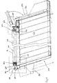
- FIG. 1 In the side view sketched in FIG. 1 as a view of the left side wall LSL a container which according to a preferred application as Transport trough of a truck is formed under recess a middle section front part and rear part of the container shown.
- the front end faces the driver's cab of the truck in the usual way and contain lifting equipment in the form of a hydraulic cylinder, for example HZ for lifting the container from the front, which is then used as a tipping trough is designed with a fold-out rear wall RW at the rear of the container.
- the Front STF and the rear side STH of the container are the end faces in the Difference to the long sides LSL, LSR designated.
- the container is after open at the top and this container opening for loading is through the tarpaulin lockable.
- a belt strap GB is anchored on one side of one of the side walls, which with the winding direction opposite to the tarpaulin PL on a with the shaft WE, on which the tarpaulin PL is wound, non-rotatably connected
- Belt reel GR can be wound up as a winding tube.
- a similarly constructed belt tensioning device is provided at the rear end of the shaft (right in Fig. 1) and in Fig. 3 shown in more detail.
- the tarpaulin PL has a longitudinal edge on a long side LSR of the container attached and with the container opening exposed on the parallel to the long side of the container extending shaft WE rolled up, on which it with the other Longitudinal tarpaulin edge is attached.
- the rolled tarp is preferably in one Shot on the longitudinal side of the LSR.
- the edges between the container opening on the front and rear sides between the long sides are the front edges SKF on the front and SKH on the rear designated.
- the front edges can be against the container walls in the longitudinal direction be offset.
- the front edges are parallel to one another and advantageously horizontally straight. According to another advantageous embodiment, can the front edges are arched upwards and therefore already higher Take the load into account.
- the tarpaulin covers in the longitudinal direction of the Vehicle still both front edges and rolls, as far as the load does not over the protruding surface between the front edges, on the front edges from.
- the front edges are advantageously with a first KV1 and those on top rolling edge sections of the tarpaulin transverse edges with the corresponding one other part KV2 provided a Velcro device so that when rolling the tarpaulin under the influence of the pressure force of the tarpaulin under the weight of the shaft and any tarpaulin still wound thereon a reliable Velcro connection results, which in particular against lateral Tensile forces is stable.
- the tarpaulin acts through the rolling movement the pulling forces perpendicular to the Velcro connection surface and allow a non-destructive solution to the Velcro connection.
- the tarpaulin shaft can the rolling movement in the longitudinal direction of the vehicle over the front edges of the container be guided, for example by engagement of a web on the front edge in a Annular groove of a roller connected to the tarpaulin shaft, in particular also the belt tensioner, or by one running along the outside of the front edges Collar of the belt roll etc.
- the Velcro device is also independent of the mechanism of the Shaft displacement advantageous.
- a bead, a bead or the like on the Front edges can improve the sealing of the tarp along the support surfaces the front edges can be achieved by the tarpaulin in particular upward arched face rests on the bead under increased tension.
- Fig. 4 shows a preferred embodiment of a rear strap arrangement.
- the belt reel GRD is coaxial to the shaft WE and rotatable relative to this about the common axis.
- the Shaft WE is designed at least in sections as a tube, in which it is secured against rotation a driver arrangement MA, for. B. in the form of a disc Web etc. is used spaced from the shaft end.
- a coiled feather WF is within the pipe section between the driver arrangement and the belt reel GRD arranged around a coaxial retaining bolt BO and with one End FE1 in the driver arrangement and with its other end FE2 in the GRD belt reel attached.
- the rotatable belt reel GRD is by means of holding means Sl axially secured on the bolt BO.
- the spring WF is initially twisted after untensioned assembly the belt reel GRD biased relative to the shaft WE in the direction that the Spring tension tightens the webbing.
- the belt reel continues against the shaft twisted, so the spring tension increases and ensures with decreasing Webbing a tight winding of the webbing on the belt reel or
- the rotatability of the belt reel and tarpaulin shaft under the spring tension also takes into account in particular the Shaft displacement changing and i. a. different winding diameters of tension band and tarpaulin.
- the rotatability of the belt reel relative to the shaft can vary depending on the application also encompass several revolutions.
- the spring tension can influenced by parameters of the spring and the initial preload become.
- the lever arrangement consists of a rigid lever H01, which at its end opposite the tarpaulin shaft in a backdrop K1 or a functionally comparable guideway is led.
- the lever can be displaceable in the backdrop, for example Sliding block, a roller, a ball bearing, etc., which forms a movable support point APM.
- the angle of inclination W1 of Lever H01 against the course of the backdrop K1 can depend on the position of the tarpaulin shaft vary quantitatively, but the qualitative orientation of the lever against the backdrop in such a way that the lever z. B. always inclined to the left be the same for all positions.
- the backdrop is wide Area essentially horizontal near the front edge SKF of the front End face STF and swivels in the area of the end position E1 or Longitudinal side down LSL. The one initially when the tarpaulin is unwound the support point tapering towards the end position E1 is removed when approaching the tarpaulin shaft to the end position E1 from this end position.
- the lever can be chosen long enough or additional ones Means to ensure the selected defined direction of inclination be provided.
- additional means can be used, for example, as stop elements limit and / or can limit a range of inclination angles by means of spring elements, which are preferably also in or on the Support the backdrop, work towards reducing the angle W1.
- FIG. 7 also shows a one-piece lever H03, which but does not have a specific end point as a support point, but slidably arranged in a stationary manner with respect to the end face STF of the container, rotatable sleeve GH is guided.
- rotatable sleeve GH is guided.
- a backdrop is a special case Guide rail K4 arranged a short distance from the end face STF.
- a lever H04 of the lever arrangement is located in a guide space Guide rail K4 and end face and is attached by an anti-pull-out device AS the lever end facing away from the tarpaulin shaft against being pulled out of the guide space secured.
- the lever is in an intermediate position Z14 Tarpaulin shaft within the guide room between two positions each can be pivoted up to the stop of the pull-out protection on the guide rail and is in the intermediate position depending on the direction of displacement of the tarpaulin shaft Z14 take one of the two positions shown.
- FIGS. 9 to 11 each have multi-part lever arrangements with at least two lever elements movable relative to each other between the tarpaulin shaft and the support point.
- the lever arrangement consists of two relative to one another longitudinally displaceable lever elements H05 and H15, which in particular can be telescoped and a kink-resistant length variable Form lever arrangement.
- This enables one close to the SKF front edge Arrangement of the fixed support point APF around which the lever arrangement is pivotable.
- the length of the lever arrangement is then in a middle intermediate position the shifted tarpaulin shaft minimal and in the end positions of the Tarpaulin shaft maximum.
- the change in length can be influenced or against a spring force.
- the lever arrangement consists of two articulated lever elements H 06 and H16, from which the first lever element H06 to the tarpaulin shaft and the second lever element leads to the displaceably guided support point APM.
- the base is performed in a backdrop K6, which is preferably near the Front edge SKF runs parallel to this and / or horizontally.
- the lever elements are dimensioned so that an extension of the lever arrangement on a WW angle between the two lever elements of less than 180 Degree for the end positions and all intermediate positions of the tarpaulin shaft as a distance between tarpaulin shaft and backdrop is sufficient.
- the lever arrangement is preferably located in all positions, but at least in the end positions of the tarpaulin shaft substantially within the LSR and through the container sidewalls LSL and the tarpaulin cover profile of limited cross-section. In intermediate positions the tarpaulin shaft can the lever arrangement depending on the size and direction assume different positions on the force exerted on the tarpaulin shaft as indicated.
- the angle WW between the lever elements can to a range of e.g. B. 10 degrees to 170 degrees. Not one Drawn spring arrangement can extend or bend in the joint the lever arrangement act.
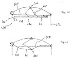
- the embodiment outlined in FIG. 11 provides a lever arrangement with two articulated lever elements H07 and H17 between the tarpaulin shaft and a fixed support point APF, the lever arrangement in all positions of the tarpaulin shaft are angled in the same direction.
- the fixed support point can be close to the SKF front edge.
- a lever arrangement with a drive motor is outlined in Fig. 11 in side view and in Fig. 12 with a view in the longitudinal direction.
- the lever or, in the case of multi-part lever arrangements, that which extends to the tarpaulin shaft Lever element HO is rotatably mounted and encloses relative to the tarpaulin shaft for example the bolt BO outlined in FIG. 4 or as outlined an inner tube RO taking over its function.
- a gear wheel is over the tube RO is connected to the tarpaulin shaft in a rotationally fixed manner.
- a gear AZ as a drive is, for example, rotationally fixed to the inner tube via a drive shaft ZW RO and thus connected to the tarpaulin shaft WE.
- Other forms of transmission such as B. via bevel gear, spur gear with parallel axis alignment, Belt drives, friction wheel drives, drive forms with overload protection etc. can also be implemented.
- a motor can also be used integrated transmission gear or a slow running due to the design Motor with a drive shaft to be connected directly to the inner tube RO.
- a drive means for transmission the motor force on the tarpaulin shaft are known to the person skilled in the art.
- the worm drive is advantageously self-locking, so that in the end positions before switching off of the motor a winding tension which secures the position Part (tarpaulin or strap) can be generated, which after switching off the engine is held.
- a rotation of the motor shaft is over the Worm drive in a rotation of the gear AZ relative to the lever element HO implemented.
- the drive motor can also be spaced further from the tarpaulin shaft, then the driving force, for example, via an extension of the drive shaft or other power transmission means known per se including Chain, belt, etc. to the tarpaulin shaft or one with it in rotation connected drive means is directed.
- the drive means can also be used with a limited rotatable against the restoring force against a restoring force Tension tape roll to be connected.
- the Lever HO rotatable in a support point APM on a guide plate LP attached, which in turn along a backdrop, preferably the in Fig. 5 outlined type, is slidable.
- the guide plate LP runs outside the backdrop KU, which is firmly connected to the container end wall, for example via a link bracket KT.
- the guide plate LP supports laterally from the support point APM spaced two ball bearings KL, which within the Backdrop KU run. This ensures that the guide plate runs smoothly along the backdrop and largely prevents the guide plate from tilting and the camp against the backdrop.
- FIG. 11 Formation of a bead PS (or a corresponding elevation), which extends along the course of the front edge extends between the opposite long sides.
- a bead PS or a corresponding elevation
- the front edge is, for example, as with a corrugated sheet metal strip on a connected to the container Support profile STT with arched upper course attached and fastened.
- FIG. 12 EO An exemplary receptacle PA for the tarpaulin shaft in the end position is shown in FIG. 12 EO can be seen to the side as protection and support.
- the fixed tarpaulin longitudinal edge PLF can advantageously in a longitudinal profile of the container structure hung and between tarpaulin structure and such a longitudinal profile be fixed.
- a separate Strips of a flexible sealing tarpaulin DP can be provided.
- the invention is not restricted to the exemplary embodiments described, but can be modified in many ways within the scope of professional skills. In particular, there are great variations in the design and supporting the lever arrangement with one or more lever elements.
- the motor drive can also act on the belt roll.
Landscapes
- Engineering & Computer Science (AREA)
- Mechanical Engineering (AREA)
- Winding Of Webs (AREA)
- Wrappers (AREA)
- Storing, Repeated Paying-Out, And Re-Storing Of Elongated Articles (AREA)
Abstract
Description
- Fig. 1
- einen Behälter in Seitenansicht
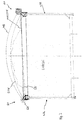
- Fig. 2
- eine Ansicht von der Heckseite
- Fig. 3:
- eine Seitenansicht der Spannbandanordnung aus Fig. 2
- Fig. 4:
- eine bevorzugte Spannbandeinrichtung
- Fig. 5:
- einen Antriebsmotor auf einer Hebelanordnung
- Fig. 6 bis Fig. 12:
- verschiedene vorteilhafte Hebelanordnungen
Claims (27)
- Vorrichtung zur Abdeckung eines Behälters, insbesondere eines Fahrzeug-Muldenbehälters, durch eine Abdeckplane, welche durch Verlagern einer Welle zwischen gegenüberliegenden Längsseiten des nach oben offenen Behälters von der Welle abrollbar bzw. auf diese aufrollbar ist, dadurch gekennzeichnet, daß die Welle an einer verlagerbaren Hebelanordnung angelenkt und mit einem Antriebsmittel gekoppelt ist, welches unter der Einwirkung eines motorischen Antriebs auf die Welle eine diese um ihre Längsachse gegen die Hebelanordnung verdrehende Kraft ausübt, wobei die Hebelanordnung von der Wellenachse beabstandet gegen die Reaktionskraft der Verdrehung abgestützt ist.
- Vorrichtung nach Anspruch 1, dadurch gekennzeichnet, daß die Hebelanordnung an der Stirnwand des Behälters abgestützt ist.
- Vorrichtung nach Anspruch 1 oder 2, dadurch gekennzeichnet, daß die Hebelanordnung einen in einer bezüglich des Behälters festen Kulisse geführten Abstützpunkt aufweist.
- Vorrichtung nach Anspruch 3, dadurch gekennzeichnet, daß die Kulisse zwischen den Längsseiten an einer Stirnkante im Bereich der Behälterkante verläuft.
- Vorrichtung nach Anspruch 3 oder 4, dadurch gekennzeichnet, daß die Kulisse einen Umkehrpunkt zum Verkippen der Ausrichtung der Hebelanordnung aufweist.
- Vorrichtung nach Anspruch 3 oder 4, dadurch gekennzeichnet, daß die Kulisse im Bereich einer Längsseite des Behälters nach unten umgelenkt ist.
- Vorrichtung nach einem der Ansprüche 3 bis 6, dadurch gekennzeichnet, daß eine Verschwenkung der Hebelanordnung gegen die Kulisse durch Begrenzungsmittel eingeschränkt ist.
- Vorrichtung nach einem der Ansprüche 3 bis 7, dadurch gekennzeichnet, daß die Hebelanordnung gegen die Kulisse entgegen einer Rückstellkraft verschwenkbar ist.
- Vorrichtung nach Anspruch 1 oder 2, dadurch gekennzeichnet, daß die Hebelanordnung an einem festen Abstützpunkt angelenkt ist.
- Vorrichtung nach einem der Ansprüche 1 bis 9, dadurch gekennzeichnet, daß die Hebelanordnung einen starren Hebel zwischen Abstützpunkt und Wellenachse aufweist.
- Vorrichtung nach einem der Ansprüche 1 bis 10, dadurch gekennzeichnet, daß der Abstand zwischen Abstützpunkt und Wellenachse veränderlich ist.
- Vorrichtung nach Anspruch 11, dadurch gekennzeichnet, daß die Hebelanordnung wenigstens zwei relativ zueinander bewegbare Hebelelemente zwischen Abstützpunkt und Wellenachse aufweist.
- Vorrichtung nach Anspruch 11 oder 12, dadurch gekennzeichnet, daß wenigstens zwei Hebelelemente teleskopartig gegeneinander verschiebbar verbunden sind.
- Vorrichtung nach einem der Ansprüche 11 bis 13, dadurch gekennzeichnet, daß wenigstens zwei Hebelelemente gelenkig miteinander verbunden sind.
- Vorrichtung nach einem der Ansprüche 1 bis 14, dadurch gekennzeichnet, daß der motorische Antrieb bei Erreichen der Endlagen der Verlagerung der Planenwelle automatisch abgeschaltet wird.
- Vorrichtung nach einem der Ansprüche 1 bis 15, gekennzeichnet durch einen Elektromotor oder einen Hydraulikmotor als motorischen Antrieb.
- Vorrichtung nach Anspruch 16, gekennzeichnet durch Überwachungseinrichtungen zur Überwachung des Motorstroms bzw. des Drucks der Hydraulikflüssigkeit.
- Vorrichtung nach einem der Ansprüche 1 bis 17, dadurch gekennzeichnet, daß der Antriebsmotor an der Hebelanordnung in der Nähe der Wellenachse angeordnet ist.
- Vorrichtung nach einem der Ansprüche 1 bis 18, dadurch gekennzeichnet, daß das Antriebsmittel ein Zahnrad umfaßt, welches mit dem Antriebsmotor über einen Zahn- oder Schneckentrieb in Verbindung steht.
- Vorrichtung nach einem der Ansprüche 1 bis 19, gekennzeichnet durch eine Spannbandanordnung an einer oder vorzugsweise beiden Enden der Planenwelle.
- Vorrichtung nach Anspruch 20, dadurch gekennzeichnet, daß eine koaxiale zur Planenwelle angeordnete Spannbandrolle entgegen einer Rückstellkraft um ein begrenztes Maß gegen die Welle verdrehbar ist.
- Vorrichtung nach Anspruch 21, dadurch gekennzeichnet, daß das Spannband in jeder Position der Wellenverlagerung unter Einwirkung einer Federspannung gespannt ist.
- Vorrichtung nach einem der Ansprüche 1 bis 22, dadurch gekennzeichnet, daß an beiden Enden der Welle gleichartige Hebelanordnung vorgesehen ist.
- Vorrichtung nach Anspruch 23, dadurch gekennzeichnet, daß nur an einem Wellenende ein motorischer Antrieb vorgesehen ist.
- Vorrichtung nach Anspruch 23, dadurch gekennzeichnet, daß an beiden Wellenenden je ein Antriebsmotor vorgesehen ist.
- Vorrichtung nach einem der Ansprüche 1 bis 25, gekennzeichnet durch eine Niederhalteeinrichtung für die abgerollte Abdeckplane an wenigstens einer Stirnseite.
- Vorrichtung nach Anspruch 26, gekennzeichnet durch eine Klettverschlußeinrichtung als Niederhalteeinrichtung.
Priority Applications (1)
| Application Number | Priority Date | Filing Date | Title |
|---|---|---|---|
| DE20023740U DE20023740U1 (de) | 1999-11-09 | 2000-11-03 | Vorrichtung zur Abdeckung eines Behälters durch eine Abdeckplane |
Applications Claiming Priority (2)
| Application Number | Priority Date | Filing Date | Title |
|---|---|---|---|
| DE19953673 | 1999-11-09 | ||
| DE1999153673 DE19953673A1 (de) | 1999-11-09 | 1999-11-09 | Vorrichtung zur Abdeckung eines Behälters durch eine Abdeckplane |
Publications (2)
| Publication Number | Publication Date |
|---|---|
| EP1099586A2 true EP1099586A2 (de) | 2001-05-16 |
| EP1099586A3 EP1099586A3 (de) | 2002-05-02 |
Family
ID=7928285
Family Applications (1)
| Application Number | Title | Priority Date | Filing Date |
|---|---|---|---|
| EP00123981A Withdrawn EP1099586A3 (de) | 1999-11-09 | 2000-11-03 | Vorrichtung zur Abdeckung eines Behälters durch eine Abdeckplane |
Country Status (2)
| Country | Link |
|---|---|
| EP (1) | EP1099586A3 (de) |
| DE (1) | DE19953673A1 (de) |
Cited By (3)
| Publication number | Priority date | Publication date | Assignee | Title |
|---|---|---|---|---|
| CN108134030A (zh) * | 2018-01-17 | 2018-06-08 | 安徽机电职业技术学院 | 一种电动汽车用电池安装箱 |
| CN111186634A (zh) * | 2020-02-24 | 2020-05-22 | 闽侯县隆森工艺制品有限公司 | 一种防潮储存运输木箱 |
| WO2022166415A1 (zh) * | 2021-02-07 | 2022-08-11 | 南通中集特种运输设备制造有限公司 | 篷布及集装箱组件 |
Families Citing this family (3)
| Publication number | Priority date | Publication date | Assignee | Title |
|---|---|---|---|---|
| DE202008015088U1 (de) | 2008-11-14 | 2009-01-15 | Meininger, Steffen | Vorrichtung zur Abdeckung eines Behälters und Fahrzeug-Muldenbehälter |
| DE102012102049A1 (de) * | 2012-03-12 | 2013-09-12 | Oberleitner Windschutz GmbH & Co. KG | LKW-Abdeckung mit Schwenkarm |
| DE102012023610B4 (de) * | 2012-12-04 | 2025-12-18 | Günter Bauregger | Rolleinrichtung eines Seitenverdecks eines Lastfahrzeuges und Verfahren zur Steuerung des Rollvorganges |
Citations (1)
| Publication number | Priority date | Publication date | Assignee | Title |
|---|---|---|---|---|
| DE2822451C2 (de) | 1977-05-23 | 1988-05-19 | Sture Bjuraaker Se Fredin |
Family Cites Families (3)
| Publication number | Priority date | Publication date | Assignee | Title |
|---|---|---|---|---|
| US4023857A (en) * | 1975-04-24 | 1977-05-17 | Rose Killion | Tensioned and retractable truck body tarpaulin |
| US4673208A (en) * | 1986-01-02 | 1987-06-16 | Masa Tsukamoto | Power-operated, extendible and retractible cover for truck beds |
| US5002328A (en) * | 1989-06-06 | 1991-03-26 | Walter Michel | Drive system for flexible cover |
-
1999
- 1999-11-09 DE DE1999153673 patent/DE19953673A1/de not_active Withdrawn
-
2000
- 2000-11-03 EP EP00123981A patent/EP1099586A3/de not_active Withdrawn
Patent Citations (1)
| Publication number | Priority date | Publication date | Assignee | Title |
|---|---|---|---|---|
| DE2822451C2 (de) | 1977-05-23 | 1988-05-19 | Sture Bjuraaker Se Fredin |
Cited By (4)
| Publication number | Priority date | Publication date | Assignee | Title |
|---|---|---|---|---|
| CN108134030A (zh) * | 2018-01-17 | 2018-06-08 | 安徽机电职业技术学院 | 一种电动汽车用电池安装箱 |
| CN108134030B (zh) * | 2018-01-17 | 2024-04-05 | 安徽机电职业技术学院 | 一种电动汽车用电池安装箱 |
| CN111186634A (zh) * | 2020-02-24 | 2020-05-22 | 闽侯县隆森工艺制品有限公司 | 一种防潮储存运输木箱 |
| WO2022166415A1 (zh) * | 2021-02-07 | 2022-08-11 | 南通中集特种运输设备制造有限公司 | 篷布及集装箱组件 |
Also Published As
| Publication number | Publication date |
|---|---|
| DE19953673A1 (de) | 2001-05-10 |
| EP1099586A3 (de) | 2002-05-02 |
Similar Documents
| Publication | Publication Date | Title |
|---|---|---|
| DE69824626T2 (de) | Lösbare bremse für rollos und andere fensterabdeckungen | |
| DE102011113207B4 (de) | Fahrzeugrolloanordnung und Fahrzeugdach | |
| EP1112876A2 (de) | Sonnenschutzvorrichtung für einen lichtdurchlässigen Fahrzeugdachbereich | |
| EP1099586A2 (de) | Vorrichtung zur Abdeckung eines Behälters durch eine Abdeckplane | |
| DE19539848A1 (de) | Rollo, insbesondere für Fahrzeuge | |
| DE2356904A1 (de) | Auslegerkran | |
| DE60027662T2 (de) | Abdeckplane für Lastkraftwagen | |
| DE102015219178B4 (de) | Lastentransportbehälter mit Rollplane aufweisend einen Regenablauf und damit ausgerüstetes Lastentransportfahrzeug | |
| DE102007035072B4 (de) | Rollo für ein Kraftfahrzeugseitenfenster mit Fensterteilungssteg | |
| EP0669447A1 (de) | Sonnenschutzvorrichtung | |
| DE102005021399B4 (de) | Rollo für Fahrzeugfenster | |
| DE4207504A1 (de) | Trommelwinde | |
| DE20023740U1 (de) | Vorrichtung zur Abdeckung eines Behälters durch eine Abdeckplane | |
| EP1609668B1 (de) | Baueinheit für einen Anhänger | |
| EP1099585A2 (de) | Vorrichtung zur Abdeckung eines Behälters durch eine Abdeckplane | |
| DE3151618C2 (de) | Bandabdeckung einer Führungsbahn für einen Schlitten an einer Werkzeugmaschine | |
| EP1870271B1 (de) | Fensterrollo für ein Fahrzeugfenster | |
| DE602005004905T2 (de) | Steuervorrichtung zum Öffnen und Schliessen eines oben offenen Behälters für Nutzfahrzeuge | |
| DE69313096T2 (de) | Handbetriebene Vorrichtung zum Wickeln von Wickelgut auf eine Welle oder eine Trommel | |
| DE29906315U1 (de) | Fensterrollo | |
| EP0687642B1 (de) | Vorrichtung zum Speichern sowie zum Auf- und Abwickeln eines flexiblen, biegsamen Stabes | |
| DE2822451A1 (de) | Anordnung zum ueberdecken einer schnitzelkiste | |
| AT521742B1 (de) | Seitenrollabdeckung für die Rollplanenabdeckung eines LKW mit Sattelaufleger | |
| DE19829209C2 (de) | Stellantrieb, insbesondere Fensterheber- bzw. Schiebedachantrieb für ein Kraftfahrzeug | |
| DE69000703T2 (de) | Vorrichtung, um ein sonnenschirmtuch unter spannung zu halten, insbesondere fuer eine veranda oder pergola. |
Legal Events
| Date | Code | Title | Description |
|---|---|---|---|
| PUAI | Public reference made under article 153(3) epc to a published international application that has entered the european phase |
Free format text: ORIGINAL CODE: 0009012 |
|
| AK | Designated contracting states |
Kind code of ref document: A2 Designated state(s): DE ES FR IT Kind code of ref document: A2 Designated state(s): AT BE CH CY DE DK ES FI FR GB GR IE IT LI LU MC NL PT SE TR |
|
| AX | Request for extension of the european patent |
Free format text: AL;LT;LV;MK;RO;SI |
|
| PUAL | Search report despatched |
Free format text: ORIGINAL CODE: 0009013 |
|
| AK | Designated contracting states |
Kind code of ref document: A3 Designated state(s): AT BE CH CY DE DK ES FI FR GB GR IE IT LI LU MC NL PT SE TR |
|
| AX | Request for extension of the european patent |
Free format text: AL;LT;LV;MK;RO;SI |
|
| 17P | Request for examination filed |
Effective date: 20021104 |
|
| AKX | Designation fees paid |
Free format text: DE ES FR IT |
|
| STAA | Information on the status of an ep patent application or granted ep patent |
Free format text: STATUS: THE APPLICATION HAS BEEN WITHDRAWN |
|
| 18W | Application withdrawn |
Effective date: 20051103 |