EP1097786A2 - Bahnführungsvorrichtung mit einem Sensor - Google Patents
Bahnführungsvorrichtung mit einem Sensor Download PDFInfo
- Publication number
- EP1097786A2 EP1097786A2 EP00309829A EP00309829A EP1097786A2 EP 1097786 A2 EP1097786 A2 EP 1097786A2 EP 00309829 A EP00309829 A EP 00309829A EP 00309829 A EP00309829 A EP 00309829A EP 1097786 A2 EP1097786 A2 EP 1097786A2
- Authority
- EP
- European Patent Office
- Prior art keywords
- operation line
- detection
- robot
- sensor
- detecting
- Prior art date
- Legal status (The legal status is an assumption and is not a legal conclusion. Google has not performed a legal analysis and makes no representation as to the accuracy of the status listed.)
- Withdrawn
Links
Images




Classifications
-
- B—PERFORMING OPERATIONS; TRANSPORTING
- B25—HAND TOOLS; PORTABLE POWER-DRIVEN TOOLS; MANIPULATORS
- B25J—MANIPULATORS; CHAMBERS PROVIDED WITH MANIPULATION DEVICES
- B25J9/00—Program-controlled manipulators
- B25J9/16—Program controls
- B25J9/1679—Program controls characterised by the tasks executed
- B25J9/1684—Tracking a line or surface by means of sensors
-
- G—PHYSICS
- G05—CONTROLLING; REGULATING
- G05B—CONTROL OR REGULATING SYSTEMS IN GENERAL; FUNCTIONAL ELEMENTS OF SUCH SYSTEMS; MONITORING OR TESTING ARRANGEMENTS FOR SUCH SYSTEMS OR ELEMENTS
- G05B2219/00—Program-control systems
- G05B2219/30—Nc systems
- G05B2219/37—Measurements
- G05B2219/37009—Calibration of vision system, camera, adapt light level
-
- G—PHYSICS
- G05—CONTROLLING; REGULATING
- G05B—CONTROL OR REGULATING SYSTEMS IN GENERAL; FUNCTIONAL ELEMENTS OF SUCH SYSTEMS; MONITORING OR TESTING ARRANGEMENTS FOR SUCH SYSTEMS OR ELEMENTS
- G05B2219/00—Program-control systems
- G05B2219/30—Nc systems
- G05B2219/47—Tracing, tracking
- G05B2219/4719—Line detector with laser beam, adjustable optical axis
Definitions
- the present invention relates to an operation line tracking device for an industrial robot to perform an operation with a tool mounted on the robot while moving the tool along an operation line detected by a sensor such as a laser sensor.
- an industrial robot such as a welding robot for performing an operation such as a welding operation by detecting a position of an operation line formed on an object of the operation using a sensor such as a laser sensor and moving a tool mounted on the robot to track the detected operation line.
- the detection of the operation line is repeatedly carried out automatically under the same detecting condition and it needs an operator s service to change the detecting condition.
- the sensor fails to detect the operation line or the position of the detected operation line largely deviates from a taught operation line, it is determined that a detection error occurs.
- the detection error There is a certain cause of the detection error and thus the detection of the operation line scarcely succeeds by repeating the detection under the same detecting condition.
- the position of the detected line largely deviates from that of the taught operation line, there is a certain cause of such case and it is hard to success in detection by repeating the detection of the operation line under the same detecting condition.
- an optimal detecting condition for detecting an operation line on workpieces varies depending on a surface condition and a shape of the workpieces.
- a detection error may occur in various cases where a region of low reflectance exists on the surface of the workpiece or a region of high reflectance because of oil, etc. exists on the surface, variations of the position/posture of the workpiece is large, a scanning range of the sensor is too wide to detect an unexpected object to fail in detection, a shape of the workpiece changes to require a change of the detecting condition.
- a detection error can not be eliminated unless the detecting condition is changed.
- the change of the detecting condition has been performed by an operator manually, requiring a number of processes for recovering the automatic operation, so that an efficiency of the automatic operation of the robot is lowered.
- the present invention provides an operation line tracking device for a robot to perform an operation with a tool mounted on the robot while moving the tool along an operation line formed on an object of operation.
- the operation line tracking device comprises a detector to detect a position of the operation line with a sensor under a preset detecting condition; observing means to observe detection state of the operation line by the detector; and detecting condition changing means to automatically change or reset the preset detecting condition based on the detection state observed by the observing means.
- the operation line tracking device comprises: a detector to detect a position of the operation line using a sensor mounted on the robot under a preset detecting condition; operation stopping means to stop the operation of the robot and the detection of the operation line when the detector fails to detect the operation line; detecting condition changing means to change or reset the preset detecting condition after the detection of the operation line is stopped; operation restarting means to restart the detection of the operation line under the changed or reset detecting condition, and restart the operation of the robot when the detector succeeds in detecting the operation line under the changed or reset detecting condition.
- the sensor of the detector may comprise a laser sensor operating under a preset laser output intensity, and the detecting condition changing means may change or reset the preset laser output intensity.
- the detecting condition changing means may change or reset a detecting orientation and/or a detecting position of the sensor with respect to the object of operation.
- the detector may detect a position of the operation line using a preset operation line detection program, and the detecting condition changing means may change or reset the preset operation line detection program for another operation line detection program.
- the detecting condition changing means may have a memory storing operation line detection programs with different detection algorithms, and selects one of the operation line detection programs as the preset operation line detecting condition and selects an operation line detection program other than the preset operation line detection program after the detection of the operation line is stopped.
- the sensor of the detector may comprise a visual sensor for sensing an image of the object of operation within a preset visual field and the detecting condition changing means changes or resets the preset visual field of the visual sensor.
- the sensor may have a laser beam scanner for scanning a preset scanning region on the object of operation, and the detecting condition changing means may change or reset the visual field by changing the preset scanning region.
- the operation line tracking device of the present invention may comprises analyzing means to analyze a cause of a detection failure when the detector fails in detecting the operation line, and the detecting condition changing means may automatically change or reset the preset detecting condition in accordance with the cause of the detection failure analyzed by the analyzing means.
- the operation restarting means may restart the operation of the robot at a preset position different form the stopped position of the operation of the robot.
- An alarm message may be displayed on a display device when the detector fails in detecting the operation line for a predetermined time or times under the changed or reset detecting condition.
- At least one of information on the occurrence of the detection failure, information on the stop position of the operation of the robot, information on the detecting conditions before and after the changing or resetting of the detecting condition is stored in a memory when the detection of the operation line is restarted, and the information stored in the memory may be displayed on the display device.
- FIG. 1 schematically shows a welding robot system to which an operation line tracking device of the present invention is applied.
- a welding torch 2 and a laser sensor 3 are attached to a wrist at a distal end of an arm of a robot 1.
- Servomotors for driving axes of respective joints of the robot 1 are controlled by a robot controller 4.
- a sensor board 5 is provided in the robot controller 4.
- On the sensor board 5, a control circuit for controlling the laser sensor 3 is mounted and electrically connected with the laser sensor 3 attached to the wrist of the robot arm.
- the laser sensor 3 and the sensor board 5 constitute a detector for detecting a position of a welding line formed on an object of welding operation.
- a welding operation is performed on the basis of real-time tracking in which the welding torch 2 is moved along the welding line detected by the detector using the laser sensor 3 in advance of the welding.
- FIG. 2 shows a basic configuration of the robot controller 4 in relation with the robot 1 and the welding torch 2.
- the robot controller 4 has a CPU 41 of a micro-processor which is connected with a CPU 51 of the sensor board 5 shown in FIG. 3 through a bus 50.
- the CPU 41 is connected through the bus 50 to a ROM 42, a RAM 43, a nonvolatile memory 44, a teaching operation panel 48 with a liquid-crystal display 47, axes controllers 45 connected to servomotors on the robot 1 through servo-amplifiers 46, and an interface 49 for a power supply 6 of the torch 2.
- the ROM 42 stores a system program for generally controlling the whole system including respective components of the robot controller 4, the sensor board 5 and the power supply 6.
- the RAM 43 is used for temporary storage of computation data.
- the nonvolatile memory 44 is constituted by CMOS memory supported by a backup battery and stores set values of various parameters and taught programs for operating the robot 1 and the welding torch 2.
- the CPU 41 issues a command for igniting the torch 2 under a predetermined power source condition to the power supply 6 through the interface 49 in accordance with the taught program stored in the nonvolatile memory 44, and issues a position detection command to the sensor board 5 and correct the taught positions designated by the taught program based on the detected position of the welding line transmitted from the sensor board 5 to output the corrected position as motion commands for respective axes to the axes controllers 45.
- the axes controllers 45 performs position/velocity loop control based on feed-back signals from position/velocity detectors to drivingly control the servomotors for the respective axes so that a welding operation is performed while moving the torch along the detected welding line.
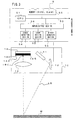
- FIG. 3 exemplifies a general structure of the position detector with the laser sensor 3 for use in this embodiment.
- a detecting section 10 has a laser oscillator 11, a swing mirror (galvanometer) 12 for scanning a laser beam LB outputted from the laser oscillator 11 and an optical system 13 for capturing a light reflected on a workpiece W to form an image on light-receiving elements 14.
- a controller on the sensor board 5 comprises a CPU 51 of a microprocessor.
- the CPU 51 is connected with an input/output interface 56, a memory 55 including ROM and RAM and the CPU 41 of the robot controller 4 through the bus 50.
- the input/output device 56 is connected with a laser driving section 52 for driving the laser oscillator 11 to generate the laser beam LB, a mirror actuating section 53 for swinging a scanning mirror 12, and a signal detecting section 54 for detecting a position of an impinged light on the light receiving elements 14.
- the CPU 51 Upon receipt of a command to detect the position of the operation line from the robot controller 4, the CPU 51 starts a program for driving the laser sensor stored in the memory 55.
- the CPU 51 issues a laser driving signal to the laser driving section 52 to generate the laser beam LB and a mirror actuating signal to the mirror actuating section 53 to swing the scanning mirror 12 for scanning the workpiece W by the laser beam LB generated by the laser oscillator 11.
- the laser beam LB diffusely reflected on a workpiece W impinges on the light receiving elements 14 through the optical system 13 at a position in accordance with a reflection position on the workpiece W.
- a linear array of CCD s (Charge Coupled Device) of light-receiving elements of a divided type, PSD (Position Sensitive Detector) of non-divided type laminated elements may be used as the light receiving elements 14.
- a linear CCD array comprising a number of cells 14-1 to 14--n is used as the light receiving elements 14.
- the light impinged on any of the cells 14-1 to 14-n is converted into photoelectron and stored in the cell.
- the electron stored in respective cells are outputted in order from the first cell 14-1 in response to a signal for scanning the CCD, and subjected by an A/D conversion to be stored and updated in the memory 55 through the signal detection section 54 and the input/output device 56.
- a scanning cycle of the CCD is set sufficiently shorter than a swinging cycle of the scanning mirror 12 and a scanning angle of the scanning mirror 12 and the corresponding signal outputting state of the CCD elements are recognized by the CPU 51.
- the outputting state of the CCD element 14 in respective CCD scanning cycles is recognized based on light detection output signals of respective cells 14-to 14-n.
- the position of the welding line formed as a recession line on the workpiece W is calculated based on the position of the cell outputting the light detection and a scanning angle of the laser beam LB by the scanning mirror 12, and the detected position of the welding line is transmitted to the robot controller 4.
- the detecting condition of the position detector is automatically changed or reset to eliminate a cause of a detection failure to continue the tracking operation, when the position detector fails to detect the welding line.
- the cause of a detection failure of the welding line is considered to be a case where the welding line can not be detected because quantity of the impinged light on the light receiving elements 14 is excessive or too small depending on a surface condition of the workpiece, a case where the welding line can not be detected because an orientation of the detecting section 10 of the laser sensor 3 with respect to the workpiece W is not appropriate, a case where the welding line is positioned at peripheral region of a visual field of the sensor 3, and a case where the welding line can not be specified because an unexpected recession line is detected besides the welding line.
- FIG. 7 schematically shows a case where the quantity of light impinged on the light-receiving elements 14 is excessive.
- a halation occurs on the light receiving elements 14 in detection of a welding line formed as a recession line between the workpiece W1 and the workpiece W2 in this embodiment, to cause a detection error.
- the welding line can be detected by reducing an output of the laser oscillator 11 to eliminate the detection error.
- a restoring operation is carried out by an operator after the robot operation and the detection operation of the welding line are stopped.
- the operation line detection is automatically carried out again by changing or resetting the condition of the operation line detection and if the detection error is eliminated and the position of the operation line is detected, the operation of the robot is continued while performing tracking of the operation line.
- FIG. 8 schematically show a case where a detection error occurs because the workpieces W1 and W2 between which a welding line is formed are inclined with respect to the sensor 3.
- the workpiece W1 and W2 are positioned in normal condition as indicated by the solid line and the orientation of the laser sensor 3 is predetermined for detecting the welding line formed between the workpieces Wl and W2.
- a detection error may occur to change the orientation of the sensor 3 with respect to the workpieces W1 and W2.
- the quantity of light impinged on the light receiving elements 14 is biased so that the quantity of light on one end of the light receiving elements 14 is made small to fail in detecting the welding line.
- the detection failure may be eliminated by changing an orientation of the sensor 3 to have a preset angle with respect to the workpieces W1 and W2. Specifically, if the quantity of light impinged on the left-hand portion of the light receiving elements 14 is small, it is determined that the workpieces W1 and W2 are inclined counterclockwise with respect to a proceeding direction of the welding operation, as shown by the dotted line, and therefore the sensor 3 should be rotated counterclockwise with respect to of the welding proceeding direction, as shown by the dotted line. On the contrary, if the quantity of light impinged on the right-hand portion of the light receiving elements 14 is small, the sensor 3 should be rotated clockwise with respect to the welding proceeding direction.
- FIG. 9 shows a case where the welding line can not detected because the welding line is displaced from the direction of motion of the sensor 3 to be scarcely detected at a peripheral portion of the light receiving elements 14.
- the position of the welding line is scarcely recognized at the periphery of the visual field of the light receiving elements 14 and the position detector fails in detecting the welding line.
- the sensor 3 should be moved so that the welding line is recognized at the center of the visual field of the sensor 3.
- the sensor 3 should be moved in the right-hand direction with respect to the welding proceeding direction, as shown by the dotted line, and in the case where the welding line is scarcely recognized at the left-hand periphery of the visual field of the sensor 3, the sensor should be moved in the left-hand direction, so that the welding line is recognized at the center of the visual field of the sensor 3.
- FIG. 10 shows a case where a detection error occurs because of variation of shape of the object of operation in the welding proceeding direction.
- the welding line between the workpiecs W1 and W2 is detected as a recession line formed by a notch between the two workpieces, and there is a case where two or more such recession lines are detected in the middle of the detection because of shape variations of the workpiece 2 in the welding proceeding direction caused by an unexpected object 200 such as a part attached to the workpiece or a foreign matter affixed on the workpiece.
- a detection error may occur because the position detector detects two or more recession lines having possibility of being the welding line.
- Such detection error is coped with by moving the sensor 3 no to detect the recession line cause by the unexpected object 200 in the same manner as shown in FIG. 9.
- the visual field of the sensor 3 is changed to avoid detection of the recession line cause by the unexpected object 200.
- an algorithm for detecting the operation line may be changed for eliminate such a detection error.
- an additional program using an algorithm for detecting the welding line which is different from the algorithm of the preset program for detecting the welding line is stored in the memory 55 so as to cope with shape variations of workpiece, and the preset and currently used welding line detection program is changed or reset to the additional program using the different detection algorithm when the detection error of the above type occurs and the detection of the welding line is attempted using the changed or reset welding line detection algorithm.
- a welding line detection program using an algorithm for detecting one notch on the object of detection and another welding line detection program using an algorithm for detecting two notches are prepared and stored in the memory 55.
- the tracking operation is started using the detection program using the algorithm for detecting one notch and when a detection error occurs in the middle of the tracking operation because of detection of two notches, the preset detection program is changed to the another detection program using the algorithm for detecting two notches to perform the welding line detection.
- a countermeasure for the detection error is taken by an operator manually.
- a countermeasure for the detection error is taken automatically in accordance with the cause of the detection error to carry out the detection again and if the welding line is successfully detected, the operation of the robot is continued with tracking of the welding line.
- FIGS. 4 to 5 show automatic restoring processing to be executed by the CPU 41 of the robot controller 4 when a detection error occurs, and welding line detection processing to be executed by the CPU 51 on the sensor board 5.
- causes of the excessive or too small quantity of the impinged light causes of the excessive or too small quantity of the impinged light
- the bias of the quantity of the impinged light, the bias of the detected position and the shape variations of a workpiece are determined as typical causes of the detection error and the restoring processing is automatically performed by changing or reset the detecting conditions.
- the automatic restoring processing may be carried out only for the cause of the most frequent error in accordance with a kind of operation and conditions of the workpieces.
- the flowchart of FIG. 4 shows the error restoring processing to be executed by the CPU 41 of the robot controller 4 and the flowchart of FIG. 5 shows processing to be executed by the CPU 41 of the robot controller 4 in response to an error signal, and the flowchart of FIG. 6 shows welding line detection processing to be executed by the CPU 51 of the sensor board 5.
- the CPU 41 of the robot controller reads a taught operation program in response to a welding start command, and actuates the welding torch 2 by outputting a power-supply condition signal to the power supply 6 of the welding torch 2.
- the CPU 41 starts a tracking operation by correcting the motion commands read out from an operation program based on the data of the position of the welding line transmitted from the sensor board 5 and outputting the corrected motion command to the axes controllers 45.
- the CPU 41 further issues a welding line detection command to the CPU 51 of the sensor board 5 (Step A1) and repeatedly determines whether an error restoring signal from the sensor board 5 is received or not (Steps A2) and whether an error signal from the sensor board 5 is received or not (Step A3).
- the CPU 51 of the sensor board 5 starts a laser sensor driving program stored in the memory 55 to issue a laser driving command to the laser driving section 52 and a mirror scanning command to the mirror actuating section 53 upon receipt of the welding line detection command from the CPU 41 of the robot controller 4 (Step B1).
- the laser beam LB scans the workpieces W1 and W2 to detect the welding line (Step B2).
- the laser beam LB diffusely reflected on the workpieces W1 and W2 forms an image on the light receiving elements 14 in accordance with a position of the reflection.
- the light impinged on the light-receiving elements 14 is converted into photo electrons and stored in the cells 14-1 to 14-N.
- the electric charge stored in the cells 14-1 to 14-N are outputted in series from one end to the other end in accordance with a CCD scanning signal at every predetermined period, and this signal is subjected to an A/D conversion through the signal detection section 54 and the input/output device 56 and stored in the memory 55.
- the CPU 51 computes the position of the welding line based on values of outputs from the cells 14-1 to 14-N stored in the memory 55 and the corresponding scanning angle of the laser beam LB.
- Step B3 the welding line detection is stopped and a flag F indicating an error state is set to "1" (Step B4) and an error signal indicating a cause of the detection error is issued to the robot controller 4.
- the CPU 51 observes the detection state of the welding line and if the quantity of light impinged on the cells 14-1 to 14-N are excessive to cause a halation to fail in detecting the welding line, a light quantity excessive signal Ela is issued. In the case where the impinged light is too small to detect the welding line, a light quantity too small signal E1b is issued (Steps B5 and B9). Then, procedure returns to Step B1.
- Step B6 if the bias of the impinged light is directed to the right hand with respect to a moving direction of the sensor 3 and the quantity of light impinged on the left-hand cells is quite small, a light quantity right-hand biasing signal E2a is issued. On the contrary, if the quantity of light impinged on the left-hand cells is quite small, a light quantity left-hand biasing signal E3b is issued (Step B 11) and the procedure returns to Step B1.
- Step B7 if the welding line positions at the right-hand periphery of the scanning region of the laser beam LB, a position right-hand biasing signal E3a is outputted, and if the welding line positions at the left-hand periphery of the scanning region of the laser beam LB, a position left-hand biasing signal E3b is outputted (Step B11), and the procedure returns to Step B1.
- the algorithm for detecting the welding line has to be changed to another one.
- the welding line detection is started with a welding line detection program using an algorithm for specifying a welding line from one detected notch.
- a signal E4 for changing the welding line detection program is issued to the CPU 41 of the robot controller 4 (Step B8, B12), and the procedure returns to Step B1.
- Step B13 In the case where a detection error causes with an appropriate quantity of the impinged light, no biases of the quantity and the position of the impinged light and no changes of the number of detected notches, an error signal E5 indicating the other cause is issued (Step B13), and the procedure returns to Step B1.
- the CPU 41 of the robot controller 4 determines whether or not an error restoring signal is received and whether or not an error signal is received from the CPU 51 of the sensor board 5 (Steps A2, A3).
- the CPU 41 stops the robot operation (Step A4) and determines whether or not the received error signal is the other error signal E5 and if the received signal is the other error signal E5, the CPU 41 issues an alarm signal for indicating an alarm by a lamp or a buzzer on the teaching operation panel 48 or a display on the liquid crystal display 47, since any countermeasure for this type of detection error is not prepared (Step A11).
- the display on the liquid crystal display 47 indicates the detection error occurs because of the other cause.
- Step A6 the automatic restoration processing shown as a subroutine of FIG. 5 is executed for each error signal.
- the error signal is the light quantity excessive signal E1a, the light quantity too small signal E1b, the light quantity right-hand biasing signal E2a, the light quantity left-hand biasing signal E2b, the position right-hand biasing signal E3a, the position left-hand biasing signal E3b or the detection algorithm changing signal E4 (Steps A20-A26).
- the CPU 41 sends a new laser output command designating a laser output intensity reduced by a predetermined value ⁇ Q with respect to the present laser output intensity designated by the present laser output command (Step A27) to the CPU 51, and the counter nl counting the number of the changes of the laser output command is increased by "1" in Step A29.
- the detecting conditions including the laser output intensity, an orientation of the sensor, a position of the sensor and the detection algorithm before and after the change of the detecting conditions, an error information, i.e. detection failure information and a stopped position of the robot are stored in the nonvolatile memory 44 in Step A37.
- Step A21 When it is determined that light quantity too small signal Elb is received in Step A21, a new laser output command is sent to the CPU 51 with the laser output intensity increased by a predetermined value ⁇ Q with respect to the present laser output intensity designated by the present laser output command in Step A28, the counter n1 is increased by "1" in Step A29, and the processing of Step A37 is carried out, to return the main routine.
- the CPU 51 on the sensor board 5 stores the laser output command in the memory 55 and drives the laser driving section 52 based on the new laser output command when restarting the welding line detection operation.
- Step A22 When it is determined that light quantity right-hand biasing signal E2a is received in Step A22, it is presumed that the orientation of the laser sensor 3 is inclined to right-hand with respect to the moving direction of the laser sensor 3 since the quantity of the impinged light from the left-hand region of the scanning region is small. Thus, the robot axes are driven such that the orientation of the laser sensor 3 is inclined to left-hand by a predetermined value ⁇ ⁇ in Step A30. Contrary, when it is determined that light quantity left-hand biasing signal E2b is received in Step A23, the robot axes are driven such that the orientation of the laser sensor 3 is inclined to right-hand by a predetermined value ⁇ ⁇ in Step A31.
- Step A32 the value of the counter n2 counting the number of the adjustments of the orientation of the laser sensor 3 is increased by "1" in Step A32, and the procedure proceeds to Step A37 where the detecting conditions before and after the detecting condition change are stored in the nonvolatile memory 44.
- Step A24 When it is determined that the position right-hand biasing signal E3a is received in Step A24, the respective axes of the robot are driven such that the position of the laser sensor 3 is moved to right-hand with respect to the moving direction of the sensor 3 by the predetermined value ⁇ L in Step A33, since an unclear but possible welding line is detected at the right-hand end of the scanning region of the laser beam LB. Contrary, it is determined that the position left-hand biasing signal E3b is received in Step A25, the laser sensor 3 is moved to left-band with respect to the moving direction of the sensor 3 by the predetermined value ⁇ L in Step A34. Then, the value of the counter n3 counting the number of the adjustments of the position of the laser sensor 3 is increased by "1" in Step A35, and the procedure proceeds to Step A37.
- Step A26 When it is determined that the error signal is the detection algorithm changing signal E4 in Step A26, a command for selecting the other detecting algorithm is issued to the CPU 51 on the sensor board 5 in Step A36 and the procedure proceeds to Step A37.
- the CPU 51 on the sensor board 5 stores the detection algorithm changing command in the memory 55 and selects the welding line detecting program in accordance with the detection algorithm changing command when restarting the welding line detection operation.
- Step A37 After executing the processing of Step A37, the procedure returns to the main routine shown in FIG. 4 and the CPU 41 determines whether or not the values of the counters n1-n3 are smaller than the set value N in Step A7. If the values of the counters n1-n3 are smaller than the set value N in Step A7, a welding line detection restart command is issued to the CPU 51 on the sensor board 5 in Step A8, and the procedure returns to Step A2.
- Step B2 when the CPU 51 on the sensor board 5 determines the receipt of the welding line detection restart command in Step B1, the welding line detection processing of Step B2 is started.
- the laser driving section 52 is driven based on the renewed and stored laser output command so that the output of the laser oscillator 11 is changed to be of the value designated by the new laser output command.
- the detection algorithm changing command has been issued, the detection algorithm is changed to the other one designated by the detection algorithm changing command.
- Step B3 when it is determined that a detection error occurs in Step B3, the processing of Step B4 and the subsequent steps are executed.
- Step B3 it is determined whether the flag F1 is "1" or not. If the flag F1 is "1", it means that the processing is the first welding line detection processing after restoring the detection error and thus a detection error restored signal is issued to the CPU 41 of the robot controller 4 in Step B 15 and the flag F is set to "0" in Step B16, and the procedure returns to Step B2. Since the flag F has been set to "0" in Step B16, the processing of Steps B2, B3 and B14 is repeatedly executed to continue the welding line detection processing.
- Step A2 when it is determined that the detection error restored signal is received in Step A2, the CPU 41 of the robot controller 4 clears the counters n1-n3 in Step A2 and restarts the robot to perform the welding line tracking operation in Step A10, which has been suspended by the error signal, and the procedure returns to Step A2.
- the welding line tracking operation when the detection error signal is received, the processing of Step A4 and the subsequent Steps is performed.
- the welding line tracking operation may be restarted from the position where the welding operation and the robot operation are stopped. It is preferable to restart the welding line tracking operation at a position backward by a predetermined distance along the welding line from the position where the welding operation is stopped. Particularly, if the welding operation is restarted from the position where the welding operation is stopped due to the welding line detection error, an undesirable junction may be produced at that position.
- the detection error restoring processing is automatically performed in accordance with the cause of the detection error, as long as the cause of the detection error is predicted and the countermeasure is prepared. If it is determined that the values of the counters n1-n3 increased in Steps A29, A32 and A 35 exceed the set value in Step A8, i.e., the detection error is not restored by the N number of error restoring processes, an alarm is issued in Step A11. The alarm is displayed on the liquid crystal display 47 indicating the cause of the detection error in accordance with the error signals E1a, E1b, E2a, E2b, E3a, E3b, E5.
- indications such as “light quantity excessive”, “light quantity too small”, “light beam right-hand biasing”, “light beam left-hand biasing”, “position right-hand biasing”, “position left-hand biasing” and “the other error” is displayed on the liquid crystal display 47. Further, the position of the robot stoppage, the information on the detection failure, and the detecting conditions before and after the detecting condition change may be displayed on the liquid crystal display 47 by operating the teaching operation panel 48 for analyzing the cause of the detection failure.
- the detection algorithm is changed when an additional possible line is detected because of the unexpected object 200.
- the position and/or visual field of the sensor may be changed so that the unexpected object 200 is not detected by the sensor.
- Step B12 is replaced by the processing similar to the processing of Step B11 to issue the position biasing signal when it is determined that the unexpected object 200 is detected in Step B8.
- the CPU 51 on the sensor board 5 issues a command for moving the sensor 3 in the left-hand direction to the robot controller 4 when the unexpected object 200 is detected in the right-hand region of the visual field of the sensor 3.
- the CPU 51 issues a command for moving the sensor 3 in the right-hand direction to the robot controller 4 when the unexpected object 200 is detected in the left-hand region of the visual field of the sensor 3.
- the CPU 41 of the robot controller 4 issues a command for driving the respective robot axes so that the sensor 3 is moved in the left-hand direction by the predetermined amount ⁇ L in response to the command to move the sensor 3 in the left-hand direction, and issues a command for driving the respective robot axes so that the sensor 3 is moved in the right-hand direction by the predetermined quantity ⁇ L in response to the command to move the sensor 3 in the right-hand direction, in place of the processing of Steps A 26 and A36, and then increases the value of an additional counter.
- the right-hand and left-hand position biasing signals E3a and E3b to be issued in Step B11 may be used as the above commands to move the sensor in the right-hand direction and in the left-hand direction, respectively, so that the robot controller 4 executes the processing of Steps A24, A 33, A25, A34 and A35.
- Step B12 is replaced by processing to issue a command for changing a range of the visual field of the sensor 3 to the robot controller 4 when it is determined that the number of the detected lines are changed in Step B8.
- the robot controller 4 issues a command for changing the range of the visual field of the sensor 3 by reducing the scanning angle of the scanning mirror 12 by a predetermined angle ⁇ ⁇ in place of the processing of Step A36 to issue a command for changing the detection algorithm, when the command for changing the range of the visual field of the sensor 3 is received in Step A26 instead of the detection algorithm changing command. Then, the additional counter is increased by "1" and the procedure proceeds to Step A37.
- the CPU 51 on the sensor board 5 issues a command for driving the scanning mirror 12 in accordance with the altered scanning angle.
- the detection range of the visual sensor 3 is reduced.
- the visual field of the visual sensor 3 may be changed by displacing the scanning range of the scanning mirror 12 to scan a range displaced in a direction remote from the direction where the unexpected object 200 is detected, alternatively of reducing the scanning range of the scanning mirror 12.
- the laser sensor 3 may returned to the original stopped position or the initial visual range, and the change of the detection algorithm may be performed by the processing of Steps B12, A26 and A36.
- a detection error signal indicating the cause of the detection error is issued from the CPU 51 on the sensor board 5 to the CPU 41 of the robot controller 4 to take a countermeasure for the cause of the detection error.
- detection errors for some causes can be restored by the CPU 51 on the sensor board 5.
- countermeasures of the adjustment of the laser output against the causes of the excessive light quantity or too small light quantity, alternation of welding line detection program against the change of the numbers of the detected lines can be taken by the CPU 51 on the sensor board 5.
- the errors which can be treated by the CPU 51 may be restored by the position detector, and the error signal indicating occurrence of the error is sent to the robot controller 4 to stop the tracking operation of the robot.
- the number of the adjustments of the impinged light quantity, the impinged light biasing, the position of the sensor are counted by the counters n1, n2 and n3, respectively.
- the total number of the adjustments for restoring the detection error may be counted by a single counter.
- the detection algorithm for detecting a welding line form a single notch and the detection algorithm for detecting a welding line form two notches are prepared and stored in the memory 55 to select either of the two algorithms.
- a plurality of welding line detection programs using different algorithms for detecting the welding line may be prepared and stored in the memory 55 in accordance with predicted shapes of the workpieces on which a welding line is formed.
- the welding line detection programs of different detection algorithms may be successively selected and executed.
- the detecting condition for detecting an operation line is automatically changed or reset when a detection error occurs in a tracking operation of the robot, and the tracking operation is automatically restarted with the changed or reset detecting condition if the detection error is restored under the change or reset detection condition.
- the tracking operation of the robot operation due to the detection failure of the operation line is automatically recovered without operator's manual operation, to enhance the efficiency of the automatic robot operation.
Landscapes
- Engineering & Computer Science (AREA)
- Robotics (AREA)
- Mechanical Engineering (AREA)
- Manipulator (AREA)
- Machine Tool Copy Controls (AREA)
Applications Claiming Priority (2)
| Application Number | Priority Date | Filing Date | Title |
|---|---|---|---|
| JP31468699A JP2001129776A (ja) | 1999-11-05 | 1999-11-05 | センサを使った検出線に対する追従装置 |
| JP31468699 | 1999-11-05 |
Publications (2)
| Publication Number | Publication Date |
|---|---|
| EP1097786A2 true EP1097786A2 (de) | 2001-05-09 |
| EP1097786A3 EP1097786A3 (de) | 2004-01-28 |
Family
ID=18056340
Family Applications (1)
| Application Number | Title | Priority Date | Filing Date |
|---|---|---|---|
| EP00309829A Withdrawn EP1097786A3 (de) | 1999-11-05 | 2000-11-06 | Bahnführungsvorrichtung mit einem Sensor |
Country Status (3)
| Country | Link |
|---|---|
| US (1) | US6445979B1 (de) |
| EP (1) | EP1097786A3 (de) |
| JP (1) | JP2001129776A (de) |
Cited By (4)
| Publication number | Priority date | Publication date | Assignee | Title |
|---|---|---|---|---|
| CN102794763A (zh) * | 2012-08-31 | 2012-11-28 | 江南大学 | 基于线结构光视觉传感器引导的焊接机器人系统标定方法 |
| WO2016041768A1 (de) * | 2014-09-15 | 2016-03-24 | Blackbird Robotersysteme Gmbh | Vorrichtung zur remote-laserbearbeitung mit sensor-scannereinrichtung |
| DE102013017795C5 (de) * | 2013-10-25 | 2018-01-04 | Lessmüller Lasertechnik GmbH | Prozessüberwachungsverfahren und -vorrichtung |
| CN110103222A (zh) * | 2019-05-24 | 2019-08-09 | 北京无线电测量研究所 | 一种工业机器人碰撞检测方法 |
Families Citing this family (20)
| Publication number | Priority date | Publication date | Assignee | Title |
|---|---|---|---|---|
| JP3703411B2 (ja) * | 2001-07-19 | 2005-10-05 | ファナック株式会社 | ワーク取り出し装置 |
| AT502283B1 (de) * | 2005-07-15 | 2007-05-15 | Fronius Int Gmbh | Schweissverfahren und schweisssystem mit bestimmung der position des schweissbrenners |
| JP4792901B2 (ja) * | 2005-09-30 | 2011-10-12 | 日産自動車株式会社 | レーザ溶接装置およびその方法、ならびに照射装置 |
| JP2007275952A (ja) * | 2006-04-10 | 2007-10-25 | Universal Shipbuilding Corp | 溶接線の非接触自動検出方法及びその装置 |
| TWI337691B (en) * | 2007-07-24 | 2011-02-21 | Apparatus and method for positioning control | |
| JP5333344B2 (ja) * | 2009-06-19 | 2013-11-06 | 株式会社安川電機 | 形状検出装置及びロボットシステム |
| US10933486B2 (en) * | 2013-02-28 | 2021-03-02 | Illinois Tool Works Inc. | Remote master reset of machine |
| CN106457571A (zh) * | 2014-08-05 | 2017-02-22 | 松下知识产权经营株式会社 | 离线示教装置 |
| JP2016078211A (ja) * | 2014-10-22 | 2016-05-16 | セイコーエプソン株式会社 | ロボット |
| JP6545472B2 (ja) * | 2015-01-27 | 2019-07-17 | 蛇の目ミシン工業株式会社 | ロボット |
| JP2016181055A (ja) * | 2015-03-23 | 2016-10-13 | 株式会社東芝 | 情報処理装置 |
| CN110136208B (zh) * | 2019-05-20 | 2020-03-17 | 北京无远弗届科技有限公司 | 一种机器人视觉伺服系统的联合自动标定方法及装置 |
| US11247335B2 (en) * | 2019-07-18 | 2022-02-15 | Caterpillar Inc. | Semi-autonomous robot path planning |
| CN112318000B (zh) * | 2020-10-23 | 2022-06-03 | 成都卡诺普机器人技术股份有限公司 | 一种变压器油箱的自适应跟踪焊接方法 |
| CN112809131B (zh) * | 2021-01-18 | 2022-07-29 | 湘潭大学 | 一种激光可调式椭形槽罐焊缝跟踪传感器 |
| JP7609747B2 (ja) * | 2021-09-24 | 2025-01-07 | コベルコROBOTiX株式会社 | ウィービング制御方法、溶接制御装置、溶接システム、溶接方法及びウィービング制御プログラム |
| JP7586803B2 (ja) * | 2021-10-20 | 2024-11-19 | 株式会社神戸製鋼所 | レーザセンサを備えた溶接ロボットの制御方法、制御装置、溶接システム、およびプログラム |
| JPWO2023170764A1 (de) | 2022-03-07 | 2023-09-14 | ||
| US12564959B1 (en) * | 2023-03-20 | 2026-03-03 | Amazon Technologies, Inc. | Controlling robotic devices based on proximity detection |
| CN120533259B (zh) * | 2025-07-28 | 2025-09-19 | 江苏丰源船舶工程有限公司 | 一种四通管焊接用的操作机械手 |
Family Cites Families (25)
| Publication number | Priority date | Publication date | Assignee | Title |
|---|---|---|---|---|
| EP0118439B1 (de) * | 1982-09-07 | 1987-08-19 | Caterpillar Inc. | Anpassungsfähiges schweissystem |
| US4638227A (en) * | 1984-01-18 | 1987-01-20 | Hitachi, Ltd. | Method and apparatus for recovering normality in moving sequence of machinery |
| US4623778A (en) * | 1984-04-06 | 1986-11-18 | Cyclomatic Industries, Inc. | Optical tracker control system |
| US5475198A (en) * | 1985-11-15 | 1995-12-12 | Westinghouse Electric Corporation | Weld pool viewing system |
| US4675502A (en) * | 1985-12-23 | 1987-06-23 | General Electric Company | Real time tracking control for taught path robots |
| JPS63245388A (ja) * | 1987-03-30 | 1988-10-12 | フアナツク株式会社 | 産業ロボットにおける運動の阻害事態の警報装置 |
| JP2543091B2 (ja) | 1987-08-04 | 1996-10-16 | 株式会社明電舎 | ロボットの倣い制御装置 |
| US4907169A (en) * | 1987-09-30 | 1990-03-06 | International Technical Associates | Adaptive tracking vision and guidance system |
| US4965499A (en) * | 1987-12-31 | 1990-10-23 | Westinghouse Electric Corp | Parametric path modeling for an optical automatic seam tracker and real time robotic control system |
| US4942538A (en) * | 1988-01-05 | 1990-07-17 | Spar Aerospace Limited | Telerobotic tracker |
| DE69119327T2 (de) * | 1990-08-31 | 1997-01-09 | Mazda Motor | Diagnoseverfahren für eine Fertigungsstrasse |
| US5279309A (en) * | 1991-06-13 | 1994-01-18 | International Business Machines Corporation | Signaling device and method for monitoring positions in a surgical operation |
| US5631973A (en) * | 1994-05-05 | 1997-05-20 | Sri International | Method for telemanipulation with telepresence |
| JPH05253804A (ja) | 1992-03-09 | 1993-10-05 | Fanuc Ltd | 非接触ならい制御装置 |
| US5737500A (en) * | 1992-03-11 | 1998-04-07 | California Institute Of Technology | Mobile dexterous siren degree of freedom robot arm with real-time control system |
| US5323470A (en) * | 1992-05-08 | 1994-06-21 | Atsushi Kara | Method and apparatus for automatically tracking an object |
| JPH06179077A (ja) * | 1992-12-11 | 1994-06-28 | Fanuc Ltd | 溶接ロボットにおけるアーク溶接制御方法 |
| JP3040670B2 (ja) * | 1994-08-22 | 2000-05-15 | ファナック株式会社 | レーザセンサを用いた溶接線追従方法及びロボット制御装置 |
| JP3550191B2 (ja) | 1994-10-04 | 2004-08-04 | 積水化学工業株式会社 | 溶接ロボット |
| JP3550192B2 (ja) | 1994-10-04 | 2004-08-04 | 積水化学工業株式会社 | 溶接ロボット |
| JP3448370B2 (ja) | 1994-10-25 | 2003-09-22 | 積水化学工業株式会社 | 溶接ロボットに適用される被溶接物のエッジ部検出方法 |
| JPH08166813A (ja) * | 1994-12-14 | 1996-06-25 | Fanuc Ltd | ウィービング動作を伴うロボットのトラッキング制御方法 |
| JP3175544B2 (ja) | 1995-07-18 | 2001-06-11 | 松下電器産業株式会社 | 溶接線検出装置および検出方法 |
| JPH1034334A (ja) * | 1996-07-19 | 1998-02-10 | Fanuc Ltd | 溶接ロボット制御システム |
| JPH10264067A (ja) * | 1997-03-28 | 1998-10-06 | Fanuc Ltd | 作業線探索機能を備えたロボット−レーザセンサシステム |
-
1999
- 1999-11-05 JP JP31468699A patent/JP2001129776A/ja active Pending
-
2000
- 2000-11-06 US US09/705,885 patent/US6445979B1/en not_active Expired - Fee Related
- 2000-11-06 EP EP00309829A patent/EP1097786A3/de not_active Withdrawn
Cited By (5)
| Publication number | Priority date | Publication date | Assignee | Title |
|---|---|---|---|---|
| CN102794763A (zh) * | 2012-08-31 | 2012-11-28 | 江南大学 | 基于线结构光视觉传感器引导的焊接机器人系统标定方法 |
| CN102794763B (zh) * | 2012-08-31 | 2014-09-24 | 江南大学 | 基于线结构光视觉传感器引导的焊接机器人系统标定方法 |
| DE102013017795C5 (de) * | 2013-10-25 | 2018-01-04 | Lessmüller Lasertechnik GmbH | Prozessüberwachungsverfahren und -vorrichtung |
| WO2016041768A1 (de) * | 2014-09-15 | 2016-03-24 | Blackbird Robotersysteme Gmbh | Vorrichtung zur remote-laserbearbeitung mit sensor-scannereinrichtung |
| CN110103222A (zh) * | 2019-05-24 | 2019-08-09 | 北京无线电测量研究所 | 一种工业机器人碰撞检测方法 |
Also Published As
| Publication number | Publication date |
|---|---|
| EP1097786A3 (de) | 2004-01-28 |
| JP2001129776A (ja) | 2001-05-15 |
| US6445979B1 (en) | 2002-09-03 |
Similar Documents
| Publication | Publication Date | Title |
|---|---|---|
| EP1097786A2 (de) | Bahnführungsvorrichtung mit einem Sensor | |
| EP0554464B1 (de) | Verfahren zur diagnostizierung eines echtzeitsensors | |
| US6414711B2 (en) | Apparatus for correcting movement path of a robot and a method therefor | |
| US5715375A (en) | Robot control system for executing multi-layer welding | |
| CN109834387B (zh) | 激光加工前对外部光学系统异常进行警报的激光加工装置 | |
| US5049028A (en) | Control system of multi-joint arm robot apparatus | |
| US5536916A (en) | Method for performing automatic alignment-adjustment of laser robot and the device | |
| JPH05231836A (ja) | 物体の3次元位置・姿勢計測方式 | |
| EP0862963B1 (de) | Steuerverfahren eines schweissroboters | |
| JP6735697B2 (ja) | 溶接状態判定システム及び溶接状態判定方法 | |
| EP0938955A1 (de) | Fertigungsliniesuchverfahren, und roboter/ sensorsystem mit einem fertigungsliniesuchverfahren | |
| US20220097225A1 (en) | Repair welding system | |
| JP2020125926A (ja) | 距離画像測定装置 | |
| CN116547612A (zh) | 一种生产系统的异常检测方法及装置、生产线设备 | |
| JPH07286820A (ja) | 3次元視覚センサを用いた位置計測方法及び位置ずれ補正方法 | |
| US5668628A (en) | Detection angle control method for laser sensor | |
| EP0863430B1 (de) | Optisches Gerät mit Vorrichtung zur Korrektur einer Bewegungsunschärfe | |
| WO1994021416A1 (fr) | Procede et appareil de commande d'un robot pour soudage a l'arc | |
| US20200030908A1 (en) | Controller | |
| JPH09248687A (ja) | レーザ加工ロボット | |
| JP3550191B2 (ja) | 溶接ロボット | |
| JPH05157510A (ja) | レーザセンサの安全装置 | |
| JP3347200B2 (ja) | 半導体レーザの制御方法 | |
| KR100671022B1 (ko) | 레이저 비전 센서를 이용한 용접 로봇의 영상 상태 점검방법 | |
| JPH0215082B2 (de) |
Legal Events
| Date | Code | Title | Description |
|---|---|---|---|
| PUAI | Public reference made under article 153(3) epc to a published international application that has entered the european phase |
Free format text: ORIGINAL CODE: 0009012 |
|
| AK | Designated contracting states |
Kind code of ref document: A2 Designated state(s): AT BE CH CY DE DK ES FI FR GB GR IE IT LI LU MC NL PT SE TR |
|
| AX | Request for extension of the european patent |
Free format text: AL;LT;LV;MK;RO;SI |
|
| PUAL | Search report despatched |
Free format text: ORIGINAL CODE: 0009013 |
|
| AK | Designated contracting states |
Kind code of ref document: A3 Designated state(s): AT BE CH CY DE DK ES FI FR GB GR IE IT LI LU MC NL PT SE TR |
|
| AX | Request for extension of the european patent |
Extension state: AL LT LV MK RO SI |
|
| RIC1 | Information provided on ipc code assigned before grant |
Ipc: 7B 23K 9/127 B Ipc: 7B 23Q 35/128 B Ipc: 7G 05B 19/19 B Ipc: 7B 23Q 15/12 B Ipc: 7B 25J 9/16 A |
|
| AKX | Designation fees paid | ||
| REG | Reference to a national code |
Ref country code: DE Ref legal event code: 8566 |
|
| STAA | Information on the status of an ep patent application or granted ep patent |
Free format text: STATUS: THE APPLICATION IS DEEMED TO BE WITHDRAWN |
|
| 18D | Application deemed to be withdrawn |
Effective date: 20040729 |