EP1096651A2 - Circuit hacheur et méthode de commande pour ledit circuit hacheur - Google Patents
Circuit hacheur et méthode de commande pour ledit circuit hacheur Download PDFInfo
- Publication number
- EP1096651A2 EP1096651A2 EP00308458A EP00308458A EP1096651A2 EP 1096651 A2 EP1096651 A2 EP 1096651A2 EP 00308458 A EP00308458 A EP 00308458A EP 00308458 A EP00308458 A EP 00308458A EP 1096651 A2 EP1096651 A2 EP 1096651A2
- Authority
- EP
- European Patent Office
- Prior art keywords
- switching
- circuit
- charging
- chopper
- voltage
- Prior art date
- Legal status (The legal status is an assumption and is not a legal conclusion. Google has not performed a legal analysis and makes no representation as to the accuracy of the status listed.)
- Withdrawn
Links
- 238000000034 method Methods 0.000 title claims description 26
- 244000145845 chattering Species 0.000 claims abstract description 57
- 238000001514 detection method Methods 0.000 claims description 18
- 230000002401 inhibitory effect Effects 0.000 claims description 14
- 230000005669 field effect Effects 0.000 claims description 13
- 230000004044 response Effects 0.000 claims description 12
- 230000003071 parasitic effect Effects 0.000 claims description 5
- 230000003213 activating effect Effects 0.000 claims description 2
- 230000002265 prevention Effects 0.000 abstract description 21
- 239000003795 chemical substances by application Substances 0.000 description 38
- 239000003990 capacitor Substances 0.000 description 34
- 238000010586 diagram Methods 0.000 description 29
- 101000746134 Homo sapiens DNA endonuclease RBBP8 Proteins 0.000 description 28
- 101000969031 Homo sapiens Nuclear protein 1 Proteins 0.000 description 28
- 102100021133 Nuclear protein 1 Human genes 0.000 description 28
- 230000007704 transition Effects 0.000 description 19
- 238000003708 edge detection Methods 0.000 description 18
- 101100310637 Arabidopsis thaliana SON1 gene Proteins 0.000 description 15
- 101100417245 Saccharomyces cerevisiae (strain ATCC 204508 / S288c) RPN4 gene Proteins 0.000 description 15
- 101000652433 Homo sapiens Protein SON Proteins 0.000 description 7
- 102100030232 Protein SON Human genes 0.000 description 7
- 101100443251 Saccharomyces cerevisiae (strain ATCC 204508 / S288c) DIG2 gene Proteins 0.000 description 5
- 101100041128 Schizosaccharomyces pombe (strain 972 / ATCC 24843) rst2 gene Proteins 0.000 description 5
- 230000007423 decrease Effects 0.000 description 5
- 230000008859 change Effects 0.000 description 4
- 230000005611 electricity Effects 0.000 description 4
- 230000002093 peripheral effect Effects 0.000 description 4
- 230000006872 improvement Effects 0.000 description 3
- 238000007562 laser obscuration time method Methods 0.000 description 3
- 230000009955 peripheral mechanism Effects 0.000 description 3
- 230000000630 rising effect Effects 0.000 description 3
- 210000000707 wrist Anatomy 0.000 description 3
- 241000220317 Rosa Species 0.000 description 1
- 238000013459 approach Methods 0.000 description 1
- 230000000694 effects Effects 0.000 description 1
- 210000004247 hand Anatomy 0.000 description 1
- 230000007246 mechanism Effects 0.000 description 1
- 239000010453 quartz Substances 0.000 description 1
- VYPSYNLAJGMNEJ-UHFFFAOYSA-N silicon dioxide Inorganic materials O=[Si]=O VYPSYNLAJGMNEJ-UHFFFAOYSA-N 0.000 description 1
- 238000004804 winding Methods 0.000 description 1
Images


Classifications
-
- H—ELECTRICITY
- H02—GENERATION; CONVERSION OR DISTRIBUTION OF ELECTRIC POWER
- H02M—APPARATUS FOR CONVERSION BETWEEN AC AND AC, BETWEEN AC AND DC, OR BETWEEN DC AND DC, AND FOR USE WITH MAINS OR SIMILAR POWER SUPPLY SYSTEMS; CONVERSION OF DC OR AC INPUT POWER INTO SURGE OUTPUT POWER; CONTROL OR REGULATION THEREOF
- H02M1/00—Details of apparatus for conversion
- H02M1/38—Means for preventing simultaneous conduction of switches
-
- H—ELECTRICITY
- H02—GENERATION; CONVERSION OR DISTRIBUTION OF ELECTRIC POWER
- H02M—APPARATUS FOR CONVERSION BETWEEN AC AND AC, BETWEEN AC AND DC, OR BETWEEN DC AND DC, AND FOR USE WITH MAINS OR SIMILAR POWER SUPPLY SYSTEMS; CONVERSION OF DC OR AC INPUT POWER INTO SURGE OUTPUT POWER; CONTROL OR REGULATION THEREOF
- H02M7/00—Conversion of ac power input into dc power output; Conversion of dc power input into ac power output
- H02M7/02—Conversion of ac power input into dc power output without possibility of reversal
- H02M7/04—Conversion of ac power input into dc power output without possibility of reversal by static converters
- H02M7/12—Conversion of ac power input into dc power output without possibility of reversal by static converters using discharge tubes with control electrode or semiconductor devices with control electrode
- H02M7/21—Conversion of ac power input into dc power output without possibility of reversal by static converters using discharge tubes with control electrode or semiconductor devices with control electrode using devices of a triode or transistor type requiring continuous application of a control signal
- H02M7/217—Conversion of ac power input into dc power output without possibility of reversal by static converters using discharge tubes with control electrode or semiconductor devices with control electrode using devices of a triode or transistor type requiring continuous application of a control signal using semiconductor devices only
- H02M7/219—Conversion of ac power input into dc power output without possibility of reversal by static converters using discharge tubes with control electrode or semiconductor devices with control electrode using devices of a triode or transistor type requiring continuous application of a control signal using semiconductor devices only in a bridge configuration
Definitions
- the amount of discharge due to the through current is equal to or greater than the amount of charging obtained by the charging, resulting in a significant decrease in the charging efficiency.
- the closed-loop inhibiting section may further include a charging end determination section for determining the end of charging by detecting that the switching section for charging has been off for a given amount of time, wherein when a decision is made by the charging end determination section that the charging has ended, the off state of the switching element of the switching section for a closed loop, originally set by the off controller, is reset.
- a current path to the large-capacitance capacitor 4 is formed and, as shown by the symbol ⁇ in Fig. 1, a charging current i2 flows in the large-capacitance capacitor 4, so that the charging of the large-capacitance capacitor 4 begins (step S3).
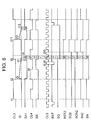
- the oscillator circuit 2A has a similar configuration to the oscillator circuit 2A of the first embodiment, and in this case, a 2-kHz clock signal CL1 and a clock signal CLX, which has a frequency higher than the clock signal CL1, for example, 32 kHz, supplied to the through current prevention circuit 20B.
- the clock signal CLX is supplied to an input terminal of the timer-counter 56.
- the present invention is not restricted in this manner, and it is possible to apply the present invention to other types of clocks, to clocks incorporated within electronic equipment such as personal computers, calculators, and mobile telephones, and further to a broad range of electronic devices, such as portable sphygmomanometers, pagers, and walking step counters. It is further possible to provide in these electronic devices both a battery and a chopper-type charging circuit, with operation done on electrical power from the battery when the stored electrical power becomes small.
- a chopper-type charging circuit of the present invention as described in detail above, in the case in which chattering occurs in the P-channel FETs P1 and P2 for charging, by forcibly setting the N-channel FETs N1 and N2 to the off state for a given amount of time, it is possible to prevent a through current flow, and to improve the charging efficiency.
Applications Claiming Priority (4)
| Application Number | Priority Date | Filing Date | Title |
|---|---|---|---|
| JP29442799 | 1999-10-15 | ||
| JP29442799 | 1999-10-15 | ||
| JP2000267547 | 2000-09-04 | ||
| JP2000267547A JP2001186771A (ja) | 1999-10-15 | 2000-09-04 | チョッパ回路、チョッパ回路の制御方法、チョッパ式充電回路、電子機器及び計時装置 |
Publications (2)
| Publication Number | Publication Date |
|---|---|
| EP1096651A2 true EP1096651A2 (fr) | 2001-05-02 |
| EP1096651A3 EP1096651A3 (fr) | 2002-02-20 |
Family
ID=26559828
Family Applications (1)
| Application Number | Title | Priority Date | Filing Date |
|---|---|---|---|
| EP00308458A Withdrawn EP1096651A3 (fr) | 1999-10-15 | 2000-09-27 | Circuit hacheur et méthode de commande pour ledit circuit hacheur |
Country Status (4)
| Country | Link |
|---|---|
| US (1) | US6304474B1 (fr) |
| EP (1) | EP1096651A3 (fr) |
| JP (1) | JP2001186771A (fr) |
| CN (1) | CN1136639C (fr) |
Cited By (1)
| Publication number | Priority date | Publication date | Assignee | Title |
|---|---|---|---|---|
| WO2011106202A3 (fr) * | 2010-02-25 | 2012-10-11 | Qualcomm Incorporated | Récepteur de puissance sans fil |
Families Citing this family (6)
| Publication number | Priority date | Publication date | Assignee | Title |
|---|---|---|---|---|
| US6545886B1 (en) * | 2001-05-05 | 2003-04-08 | Anthony J. Ireland | Power conditioning for model railroad control decoders |
| JP4696137B2 (ja) * | 2006-06-01 | 2011-06-08 | 株式会社日立製作所 | Mos整流装置 |
| US20120307537A1 (en) * | 2011-05-30 | 2012-12-06 | Stmicroelectronics S.R.L. | Rectifier circuit, method for operating the rectifier circuit, and energy harvesting system comprising the rectifier circuit |
| JP6148551B2 (ja) | 2013-06-26 | 2017-06-14 | 株式会社東芝 | 整流装置 |
| WO2017164183A1 (fr) | 2016-03-24 | 2017-09-28 | シチズンファインデバイス株式会社 | Capteur piézoélectrique |
| TWI585366B (zh) * | 2016-08-23 | 2017-06-01 | 新唐科技股份有限公司 | 計數裝置及計步裝置 |
Citations (18)
| Publication number | Priority date | Publication date | Assignee | Title |
|---|---|---|---|---|
| JPS53123653A (en) * | 1977-04-04 | 1978-10-28 | Sony Corp | Trigger circuit |
| US4238821A (en) * | 1979-04-24 | 1980-12-09 | General Electric Company | Method and apparatus for a variable frequency inverter system having commutation fault detection and correction capabilities |
| US4447867A (en) * | 1982-01-29 | 1984-05-08 | Varo, Inc. | Multiphase inverter drive circuit with synchronized switching delay feature |
| US4651269A (en) * | 1984-05-10 | 1987-03-17 | Kabushiki Kaisha Toshiba | Current flow reversing circuit |
| US4796145A (en) * | 1985-06-03 | 1989-01-03 | Mitsubishi Denki Kabushiki Kaisha | Semiconductor module |
| US4953070A (en) * | 1987-10-12 | 1990-08-28 | Siemens Aktiengesellschaft | Method for transverse-current-free operation of a push-pull circuit, and apparatus for performing the method |
| US5365118A (en) * | 1992-06-04 | 1994-11-15 | Linear Technology Corp. | Circuit for driving two power mosfets in a half-bridge configuration |
| US5449936A (en) * | 1991-11-25 | 1995-09-12 | Sgs-Thompson Microelectronics Srl | High current MOS transistor bridge structure |
| US5540729A (en) * | 1994-12-19 | 1996-07-30 | Medtronic, Inc. | Movement powered medical pulse generator having a full-wave rectifier with dynamic bias |
| EP0730340A1 (fr) * | 1994-06-27 | 1996-09-04 | Kabushiki Kaisha Toshiba | Detecteur de defaillance pour convertisseur de puissance auto-commute sur une source de tension |
| DE19634186A1 (de) * | 1995-08-28 | 1997-03-06 | Siemens Ag Oesterreich | Netzgeführte Thyristorbrücke |
| EP0862262A2 (fr) * | 1997-02-07 | 1998-09-02 | Seiko Epson Corporation | Dispositif de génération de puissance, méthode de charge et dispositif de mesure de temps |
| EP0891038A1 (fr) * | 1996-11-13 | 1999-01-13 | Seiko Epson Corporation | Dispositif d'alimentation en energie et materiel electronique portatif |
| JPH11187666A (ja) * | 1997-12-17 | 1999-07-09 | Seiko Epson Corp | チョッパ回路、チョッパ式充電回路、電子機器および腕時計 |
| JPH11187667A (ja) * | 1997-12-17 | 1999-07-09 | Seiko Epson Corp | 電源装置、発電装置および電子機器 |
| JPH11206132A (ja) * | 1998-01-05 | 1999-07-30 | Seiko Epson Corp | チョッパ回路の給電停止方法、チョッパ回路、チョッパ式充電回路、電子機器および腕時計 |
| JPH11206131A (ja) * | 1998-01-05 | 1999-07-30 | Seiko Epson Corp | スイッチングユニット、電源装置および電子機器 |
| EP0942341A1 (fr) * | 1997-09-30 | 1999-09-15 | Seiko Epson Corporation | Horloge mecanique a commande electronique et son procede de commande |
Family Cites Families (6)
| Publication number | Priority date | Publication date | Assignee | Title |
|---|---|---|---|---|
| FR2390849A1 (fr) * | 1977-05-12 | 1978-12-08 | Anvar | Commande de moteur electrique a courant continu, en particulier pour voiture electrique |
| EP0601189A4 (fr) * | 1992-06-29 | 1995-01-11 | Sekoh Giken Kk | Moteur a reluctance capable de fournir un freinage par recuperation et moteur a courant continu. |
| US5510972A (en) | 1994-06-29 | 1996-04-23 | Philips Electronics North America Corporation | Bridge rectifier circuit having active switches and an active control circuit |
| KR0173949B1 (ko) | 1995-10-16 | 1999-05-01 | 김광호 | 전파브리지 정류회로 |
| JP3522969B2 (ja) * | 1995-10-25 | 2004-04-26 | パイオニア株式会社 | Btl増幅器装置 |
| DE69623814T2 (de) | 1995-12-29 | 2003-08-07 | Em Microelectronic Marin Sa | Aktiver gleichrichter mit minimalen energieverlusten |
-
2000
- 2000-09-04 JP JP2000267547A patent/JP2001186771A/ja not_active Withdrawn
- 2000-09-27 EP EP00308458A patent/EP1096651A3/fr not_active Withdrawn
- 2000-10-11 US US09/688,272 patent/US6304474B1/en not_active Expired - Lifetime
- 2000-10-16 CN CNB001306871A patent/CN1136639C/zh not_active Expired - Fee Related
Patent Citations (18)
| Publication number | Priority date | Publication date | Assignee | Title |
|---|---|---|---|---|
| JPS53123653A (en) * | 1977-04-04 | 1978-10-28 | Sony Corp | Trigger circuit |
| US4238821A (en) * | 1979-04-24 | 1980-12-09 | General Electric Company | Method and apparatus for a variable frequency inverter system having commutation fault detection and correction capabilities |
| US4447867A (en) * | 1982-01-29 | 1984-05-08 | Varo, Inc. | Multiphase inverter drive circuit with synchronized switching delay feature |
| US4651269A (en) * | 1984-05-10 | 1987-03-17 | Kabushiki Kaisha Toshiba | Current flow reversing circuit |
| US4796145A (en) * | 1985-06-03 | 1989-01-03 | Mitsubishi Denki Kabushiki Kaisha | Semiconductor module |
| US4953070A (en) * | 1987-10-12 | 1990-08-28 | Siemens Aktiengesellschaft | Method for transverse-current-free operation of a push-pull circuit, and apparatus for performing the method |
| US5449936A (en) * | 1991-11-25 | 1995-09-12 | Sgs-Thompson Microelectronics Srl | High current MOS transistor bridge structure |
| US5365118A (en) * | 1992-06-04 | 1994-11-15 | Linear Technology Corp. | Circuit for driving two power mosfets in a half-bridge configuration |
| EP0730340A1 (fr) * | 1994-06-27 | 1996-09-04 | Kabushiki Kaisha Toshiba | Detecteur de defaillance pour convertisseur de puissance auto-commute sur une source de tension |
| US5540729A (en) * | 1994-12-19 | 1996-07-30 | Medtronic, Inc. | Movement powered medical pulse generator having a full-wave rectifier with dynamic bias |
| DE19634186A1 (de) * | 1995-08-28 | 1997-03-06 | Siemens Ag Oesterreich | Netzgeführte Thyristorbrücke |
| EP0891038A1 (fr) * | 1996-11-13 | 1999-01-13 | Seiko Epson Corporation | Dispositif d'alimentation en energie et materiel electronique portatif |
| EP0862262A2 (fr) * | 1997-02-07 | 1998-09-02 | Seiko Epson Corporation | Dispositif de génération de puissance, méthode de charge et dispositif de mesure de temps |
| EP0942341A1 (fr) * | 1997-09-30 | 1999-09-15 | Seiko Epson Corporation | Horloge mecanique a commande electronique et son procede de commande |
| JPH11187666A (ja) * | 1997-12-17 | 1999-07-09 | Seiko Epson Corp | チョッパ回路、チョッパ式充電回路、電子機器および腕時計 |
| JPH11187667A (ja) * | 1997-12-17 | 1999-07-09 | Seiko Epson Corp | 電源装置、発電装置および電子機器 |
| JPH11206132A (ja) * | 1998-01-05 | 1999-07-30 | Seiko Epson Corp | チョッパ回路の給電停止方法、チョッパ回路、チョッパ式充電回路、電子機器および腕時計 |
| JPH11206131A (ja) * | 1998-01-05 | 1999-07-30 | Seiko Epson Corp | スイッチングユニット、電源装置および電子機器 |
Non-Patent Citations (5)
| Title |
|---|
| PATENT ABSTRACTS OF JAPAN vol. 002, no. 154 (E-80), 25 December 1978 (1978-12-25) & JP 53 123653 A (SONY CORP.), 28 October 1978 (1978-10-28) * |
| PATENT ABSTRACTS OF JAPAN vol. 1999, no. 12, 29 October 1999 (1999-10-29) & JP 11 187666 A (SEIKO EPSON CORP.), 9 July 1999 (1999-07-09) * |
| PATENT ABSTRACTS OF JAPAN vol. 1999, no. 12, 29 October 1999 (1999-10-29) & JP 11 187667 A (SEIKO EPSON CORPORATION), 9 July 1999 (1999-07-09) * |
| PATENT ABSTRACTS OF JAPAN vol. 1999, no. 12, 29 October 1999 (1999-10-29) & JP 11 206131 A (SEIKO EPSON CORP.) * |
| PATENT ABSTRACTS OF JAPAN vol. 1999, no. 12, 29 October 1999 (1999-10-29) & JP 11 206132 A (SEIKO EPSON CORP.), 30 July 1999 (1999-07-30) * |
Cited By (2)
| Publication number | Priority date | Publication date | Assignee | Title |
|---|---|---|---|---|
| WO2011106202A3 (fr) * | 2010-02-25 | 2012-10-11 | Qualcomm Incorporated | Récepteur de puissance sans fil |
| US8878394B2 (en) | 2010-02-25 | 2014-11-04 | Qualcomm Incorporated | Wireless power receiver |
Also Published As
| Publication number | Publication date |
|---|---|
| US6304474B1 (en) | 2001-10-16 |
| JP2001186771A (ja) | 2001-07-06 |
| EP1096651A3 (fr) | 2002-02-20 |
| CN1293481A (zh) | 2001-05-02 |
| CN1136639C (zh) | 2004-01-28 |
Similar Documents
| Publication | Publication Date | Title |
|---|---|---|
| US6373790B1 (en) | Overcharge prevention method, changing circuit, electronic device and timepiece | |
| US6324084B1 (en) | Power supply device, power supply method, portable electronics apparatus, and electronic timepiece | |
| US6421261B1 (en) | Power supply apparatus with unidirectional units | |
| EP0862262B1 (fr) | Dispositif de génération de puissance incluant un amplificateur à découpage, méthode de charge et dispositif de mesure de temps | |
| EP1056190B1 (fr) | Dispositif d'alimentation, procede d'alimentation, dispositif electronique portatif et montre electronique | |
| JP5282502B2 (ja) | 整流制御装置、全波整流回路、受電装置、電子機器および無接点電力伝送システム | |
| EP1093212B1 (fr) | Circuit de découpeur, méthod pour un circuit de découpeur, circuit de chargement de type découpeur, dispositif éléctronic, et dispositif d'horloge | |
| JP2000287375A (ja) | 二次電池の充電回路 | |
| JP4105314B2 (ja) | Dc−dcコンバータ回路および電池駆動型装置 | |
| EP1096651A2 (fr) | Circuit hacheur et méthode de commande pour ledit circuit hacheur | |
| JP3000633B2 (ja) | 電子機器 | |
| US6421263B1 (en) | AC voltage detection circuit and method, charging circuit and method, chopper circuit and chopping method, chopper charging circuit and method, electronic apparatus, and timepiece | |
| EP0998004B1 (fr) | Procede de prevention des surcharges, circuit chargeur, dispositif electronique et compteur de temps | |
| WO2007091374A1 (fr) | Convertisseur direct de type à redressement synchrone | |
| JP5176810B2 (ja) | 整流制御装置、全波整流回路、受電装置、無接点電力伝送システムおよび電子機器 | |
| US20140183965A1 (en) | Electronic component, power feeding device, and power feeding system | |
| JP3663964B2 (ja) | 過充電防止方法、充電回路、電子機器および時計 | |
| TWI716554B (zh) | 切換調節器 | |
| KR20170042479A (ko) | 발진기용 구동 회로 | |
| US6353522B1 (en) | Switching state detecting device for switch, and electronic apparatus | |
| JP3582338B2 (ja) | スイッチングユニット、電源装置および電子機器 | |
| JP2004032980A (ja) | 過充電防止方法、充電回路、電子機器および時計 | |
| JP3680697B2 (ja) | 電子時計およびその駆動制御方法 | |
| JP2537640B2 (ja) | アナログ電子時計 | |
| JP2537642B2 (ja) | アナログ電子時計 |
Legal Events
| Date | Code | Title | Description |
|---|---|---|---|
| PUAI | Public reference made under article 153(3) epc to a published international application that has entered the european phase |
Free format text: ORIGINAL CODE: 0009012 |
|
| AK | Designated contracting states |
Kind code of ref document: A2 Designated state(s): AT BE CH CY DE DK ES FI FR GB GR IE IT LI LU MC NL PT SE |
|
| AX | Request for extension of the european patent |
Free format text: AL;LT;LV;MK;RO;SI |
|
| PUAL | Search report despatched |
Free format text: ORIGINAL CODE: 0009013 |
|
| RIC1 | Information provided on ipc code assigned before grant |
Free format text: 7H 02M 1/00 A, 7H 02M 7/219 B, 7G 04G 1/00 B |
|
| AK | Designated contracting states |
Kind code of ref document: A3 Designated state(s): AT BE CH CY DE DK ES FI FR GB GR IE IT LI LU MC NL PT SE |
|
| AX | Request for extension of the european patent |
Free format text: AL;LT;LV;MK;RO;SI |
|
| 17P | Request for examination filed |
Effective date: 20020815 |
|
| AKX | Designation fees paid |
Free format text: AT BE CH CY DE DK ES FI FR GB GR IE IT LI LU MC NL PT SE |
|
| GRAP | Despatch of communication of intention to grant a patent |
Free format text: ORIGINAL CODE: EPIDOSNIGR1 |
|
| STAA | Information on the status of an ep patent application or granted ep patent |
Free format text: STATUS: THE APPLICATION IS DEEMED TO BE WITHDRAWN |
|
| 18D | Application deemed to be withdrawn |
Effective date: 20060704 |
|
| REG | Reference to a national code |
Ref country code: HK Ref legal event code: WD Ref document number: 1034817 Country of ref document: HK |