EP1096088A2 - Contrôle de fermeture ä séquence avec dispositif de verrouillage commandé par un battant stationnaire - Google Patents
Contrôle de fermeture ä séquence avec dispositif de verrouillage commandé par un battant stationnaire Download PDFInfo
- Publication number
- EP1096088A2 EP1096088A2 EP00123078A EP00123078A EP1096088A2 EP 1096088 A2 EP1096088 A2 EP 1096088A2 EP 00123078 A EP00123078 A EP 00123078A EP 00123078 A EP00123078 A EP 00123078A EP 1096088 A2 EP1096088 A2 EP 1096088A2
- Authority
- EP
- European Patent Office
- Prior art keywords
- leaf
- sequence control
- control according
- closing sequence
- pawl
- Prior art date
- Legal status (The legal status is an assumption and is not a legal conclusion. Google has not performed a legal analysis and makes no representation as to the accuracy of the status listed.)
- Granted
Links
Images


Classifications
-
- E—FIXED CONSTRUCTIONS
- E05—LOCKS; KEYS; WINDOW OR DOOR FITTINGS; SAFES
- E05F—DEVICES FOR MOVING WINGS INTO OPEN OR CLOSED POSITION; CHECKS FOR WINGS; WING FITTINGS NOT OTHERWISE PROVIDED FOR, CONCERNED WITH THE FUNCTIONING OF THE WING
- E05F5/00—Braking devices, e.g. checks; Stops; Buffers
- E05F5/12—Braking devices, e.g. checks; Stops; Buffers specially for preventing the closing of a wing before another wing has been closed
Definitions
- the invention relates to a closing sequence control for a door closer automatically closing, double-leaf door according to the preamble of the claim 1.
- Closing sequence controls are required for double-leaf doors, if at tightly closing doors overlap the door leaves in the middle with door rebates. At such doors, the passive leaf forms a stop for the active leaf, so that the active leaf always lies against the passive leaf when the door is closed. Accordingly the passive leaf must always be closed during the closing process, before the active leaf executes at least the end of the closing path.
- the closing sequence control is required so that the right one for fire protection doors, for example Closing sequence of passive leaf and active leaf, i.e. the logical closing the double-leaf door.
- a closing sequence control corresponding to the preamble of claim 1 is known from DE 43 08 560 A1, in which the two-leaf door is a passive leaf and has an active leaf, the closing process for the active leaf can only be fully executed when the inactive leaf is closed.
- This is a locking device is provided which with a sliding arm on the active leaf a slide arranged in a slide acts. From the inactive leaf via a control lever and a thrust member provided with a saw toothing Locking element actuated, the thrust member over the axial movement Converted inclined surfaces into a vertical movement for the locking element and thereby the locking element interact with the saw teeth of the slider can.
- This locking element is under the action of vertically acting pressure springs and is only vertically movable, making a violent impact on the active leaf Closing force exerted as a result of the saw teeth as uncontrollable high force acts on the locking device.
- the structure of the locking device corresponds the closing sequence control according to DE 33 36 739 C2. This also points here Slider on its top has a serration, while that of Inactive leaf operated pushing element moves the locking element vertically.
- This Latching element has a serration on its underside, which by Thrust member to be engaged in the saw teeth of the slider can, if the passive leaf is not yet closed. Will open Inactive leaf exerts an opening force on the active leaf, so it can be skipped the serration of the active leaf can be opened further.
- the wing according to EP 0 356 728 B1 becomes a locking device with a sawtooth Locking side used, with a tooth in the toothing Can engage locking part, while this locking part can be actuated via a sliding roller is and this slide roller on a slide arm one connected to the passive leaf Door closer is arranged.
- This locking device stands over a sliding link and a coupling rod with one cooperating with the active leaf Locking member in operative connection, this locking member being crescent-shaped and by pivoting it ensures that when the passive leaf is open the active leaf cannot be closed completely.
- the locking member acts for this purpose together with a sliding roller of the door closer assigned to the active leaf.
- the sliding member mentioned consists essentially of two in extension mutually arranged sliding link parts that are coupled together are.
- the entire device for controlling the closing sequence of the door leaves consists of a large number of sometimes complicated components that are complex are to be produced. In addition to the high construction costs, assembly is also complicated, so that such a construction is very expensive and maintenance only can be done by appropriately trained personnel.
- the object of the present invention is to provide a closing sequence control to create a locking device operated by the passive leaf, which is easy in the Structure and has a problem-free assembly and maintenance.
- the one to block the closing movement of the active leaf when not closed The provided locking device exists according to the present Invention from a locking element cooperating with the locking element, this locking element is angularly movable with an articulated in the slide rail mounted trigger or can be moved at an angle with the slide rail stands and is arranged to engage in recesses of the locking element.
- Such Locking device is independent of the design and arrangement of the door closers applicable for the active and active leaf and is due to their simple Design inexpensive to manufacture and allows easy Assembly and maintenance. This applies particularly to the embodiments in which the locking element by a pawl rotatably arranged about a pivot axis is formed and this pawl with contact surfaces of the recesses of the locking element is arranged cooperatively. But it is also possible to open the jack to attach a trigger that is pivotally mounted about an axis of rotation.
- One of the two contact surfaces of the depressions of the locking element does not exercise closed passive leaf that starts in the closing direction from the active leaf Closing force on the latch. So that the trigger with the active leaf open cannot be pressed out of the locked position when on by a person A closing force is exerted on the active leaf is the slope of the contact surface of the locking element so that the closing force has a line of action, which ideally runs through the axis of rotation of the trigger is.
- there is some friction between the corresponding surfaces the pawl and the locking element must be overcome, it makes sense to to arrange corresponding surfaces of the pawl and the locking element so that the effective force of the closing force is slightly below the axis of rotation of the trigger runs.
- the other of the two contact surfaces exercises when the locking device acts and an opening movement of the active leaf exerts a force on the pawl, the causes a stroke and / or angular movement of the pawl and thus a small Opening force is sufficient to overcome the locking device. If applicable the arrangement of a return spring is conceivable, which the trigger in the locked position acted upon.
- very simple embodiments are created when the jack is arranged with its pivot axis on a lever of a trigger and the Lever around one in the slide rail or one firmly connected to the slide rail Bearing part is pivotally mounted about an axis of rotation.
- the slide piece assigned to the active leaf in the lower chamber of the slide rail arranged and stands with that in the upper chamber of the slide rail located locking element in connection, while the trigger with the locking element is arranged essentially in the lower chamber of the slide rail.
- the bearing part receiving the locking lever is preferably a positive fit in the relevant chamber of the slide rail and thus serves in Case that two separate slide rails are used for active leaf and passive leaf be used as a coupling between the slide rails.
- the connecting part can be easily Way to include a shock absorber or formed by a shock absorber be effective between the slider and the locking element and in particular the heavy leaf that may occur during the closing movement absorbs high kinetic energy.
- the shock absorber can be used as a helical compression spring device be trained, alternatively or additionally but also other designs of the shock absorber, such as elastically deformable Molded bodies or pneumatically / hydraulically functioning devices, into consideration.
- the Trigger designed as an articulated lever, which has an articulated lever piece, the on the one hand is mounted on a mounting axis and on the other hand carries the pivot axis for the pawl and with this pivot axis in one Elongated hole of the lever forming the trigger engages.
- a different one Execution with a pull rope is obtained by the fact that the pawl carrying Trigger is designed as a lever loaded by a return spring, which in a bearing part fastened in the lower chamber of the slide rail about the axis of rotation is pivotally mounted and preferably over a component that is subjected to tension a Bowden cable, with one interacting with the passive leaf Release lever is in operative connection.
- a return spring which in a bearing part fastened in the lower chamber of the slide rail about the axis of rotation is pivotally mounted and preferably over a component that is subjected to tension a Bowden cable, with one interacting with the passive leaf Release lever is in operative connection.
- These versions can also between the slider and the locking element easily in if necessary
- Train direction acting shock absorbers are installed, for example a Has tension spring, the spring movements are damped.
- the Bowden cable can itself be designed to be elastically deformable, around the heavy leaf that may occur during the closing movement absorb high kinetic energy.
- the one carrying the latch acts Lever with one operated from the passive leaf and arranged in the slide rail Sliding element together.
- the one assigned to the passive leaf Sliding element with an inclined surface, which when closed or almost closed inactive leaf with the end of the trigger Lever interacts.
- An embodiment is formed in that the locking element, preferably the Jack, is arranged in the upper chamber of the slide rail and over one Train-stressed component, for example a pull rope, with one with the Inactive leaf interacting trigger lever is connected during the Slider has an obliquely running effective surface that with the pawl cooperates. So with a strong closing force acting on the active leaf no components are damaged, either the effective surface is inclined so that the latch slides on it with large closing forces and an angular movement executes, or the pivot axis of the pawl is in one with the Sliding rail connected bearing part vertically displaceable against a spring force arranged.
- Train-stressed component for example a pull rope
- the closing sequence control to cover the door leaves and the arrangement of the door hinges is the locking block provided with an actuating surface the angle lever is arranged adjustable and comes on an effective surface an axial extension of the slider assigned to the active leaf Investment.
- the active leaf is with a sliding arm door closer and the passive leaf is equipped with a sliding arm door closer.
- the one in the slide rail of the sliding arm of the sliding door closer is with one Locking element connected.
- the sliding rail of the active leaf door closer and the Slide rail of the leaf door closer can be in a common at the top horizontal spar of the fixed frame arranged continuous Slide rail be formed.
- the actuation of the arranged in the slide rail Locking element can be made directly or indirectly from the passive leaf.
- the door closers can be surface-mounted or, in the case of advantageous designs, in the door frame be integrated.
- the slide rails can also lie on top or can be arranged integrated in the door frame in advantageous embodiments.
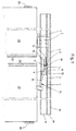
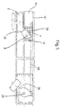
- a active leaf 20 that can be pivoted about a door hinge 24 and a passive leaf 21 that can be pivoted about a door hinge 25 is arranged, with a locking device being provided that, when the active leaf 21 is open, the closing movement of the active leaf 20 blocked so that the door rebates 22, 23 overlap when the door is closed so that the door rebate 23 of the passive leaf 21 forms the stop for the door rebate 22 of the active leaf.
- the passive leaf 21 and the active leaf 20 are each equipped with a door closer, not shown. It can be a sliding arm door closer.
- the fixed leaf 21 is shown in a still open position and the active leaf 20 in a position blocked by the locking device, the smallest has a lockable opening angle that still closes properly of the passive leaf 21 guaranteed.
- This smallest blockable opening angle of the active leaf 20 is dependent on the coverage width of the door rebate 22 and 23 and the arrangement of the door hinges 24, 25.
- the locking device points a sliding arm 1 on the one hand with the active leaf 20 and on the other hand with a slider 2 is articulated. Between the slider 2 and one Locking element 3 is a connecting part 5, for example a (here not shown) absorbs shock absorbers or even designed as shock absorbers is.
- the locking element 3 has axially one behind the other and preferably sawtooth-shaped recesses 4, in which a locking element 6 engages, this, for example, by an angularly movable about a pivot axis 8 Jack 7 is formed.
- a trigger 14 is provided with a lever 16 which is on an axis of rotation 9 arranged in a bearing part 13 is supported and on the one hand a leaf spring 15 acting on the pawl 7 and on the other hand one from the passive leaf 21 actuated role carries.
- the parts of the closing sequence control are located essentially in a slide rail 10 with an upper chamber 11 and lower chamber 12. In the upper chamber 11 that slides with the active leaf 20th related locking element 3 and the lower chamber 12 essentially takes the locking element 6 and the trigger 14.
- a surface 19 of the pawl 7 acts in the closing direction of the active leaf 20 with a relative to the direction of movement the slider steeper contact surface 17 of the locking element 3 together, while during the opening movement of the active leaf 20 a relative to the direction of movement the slider flat contact surface 18 acts on the pawl 7.
- the Slide rail 10 can be designed as a slide rail of slide arm door closers.
- the sliding arm 1 can be designed as a sliding arm of the leaf door closer.
- the housing of the active leaf door closer can be mounted on the active leaf his.
- the closing sequence control shown in FIG. 1 has a partially open position of the passive leaf 21 and active leaf 20, the active leaf 20 being held in the position by the locking device which corresponds to the smallest opening angle, so that the fixed leaf 21 can still be closed properly.
- the pawl 7 interacts with the last left recess 4 of the locking element 3 and lies with the surface 19 on the contact surface 17 acting in the closing direction.
- the closing force exerted on the active leaf 20 by the non-illustrated active leaf door closer is rotatable via the active leaf and the Transfer slide 2 connected slide arm 1 to the locking device. This closing force exerted by the active leaf door closer is considerably smaller than the holding force exerted by the locking device for the active leaf 21 when the passive leaf 21 is not closed.
- the locking element 3 is designed so long that the outermost recess 4 (on the right in the drawing) then with the latch 7 interacts when the active leaf 2 is fully open, thereby ensuring that the active leaf 2 is blocked even at large opening angles, and it is thus avoided that the locking element 3 strikes the pawl 7 at high speed, ie with high kinetic energy.
- Another opening of the active leaf 20 when the door is not closed Inactive leaf is possible in that the contact surface acting in the opening direction 18 of the locking element 3 presses the pawl and thereby the lever 16 pivots about the axis of rotation 9 and the axial movement of the locking element 3 releases.
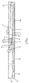
- FIG. 2 shows an embodiment of the closing sequence control without the two-leaf door.
- the slider 2 which is displaceable in the lower chamber 12 of the slide rail 10 and which is connected in an articulated manner to the slide arm 1 engaging on the active leaf, is fastened via a traction cable 30 and a deflection roller 32 to the locking element 3 which can be displaced in the upper chamber 11 of the slide rail 10.
- a tensioning device acts, which consists of a tension spring 31, for example, in the form of a rubber or elastomer rope.
- the trigger 14 has an articulated lever which has an articulated lever piece 33 which is mounted on the one hand on a fastening axis 34 and on the other hand carries the pivot axis 8 for the pawl 7.
- the leaf spring 15 cooperating with the pawl 7 is fastened to the articulated lever piece 33.
- the articulated lever piece 33 engages in an elongated hole in the lever 16 which is pivotable about the axis of rotation 9. Since the locking element 3 is subjected to tension in the closing direction of the active leaf when the inactive leaf is not or not completely closed, the contact surface 17 acts on the pawl 7 in this direction, while in the opening direction of the active leaf the contact surface 18 acts on the pawl 7 and presses it downward .
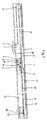
- FIG. 3 differs from that of FIG. 2 essentially by a different type of trigger 14 and its connection to a release lever 26 which can be actuated by the passive leaf.
- This connection is made by a Bowden cable 28 which, on the one hand, is connected to the release lever 26 which can be pivoted about a bolt 29 is attached and on the other hand is connected in such a way to the pivotable lever 16 about the axis of rotation 9 that when the inactive leaf acts on the roller of the release lever 26, the lever 16 is pivoted against the force of a return spring 27 about the axis of rotation and thereby the pawl mounted on the pivot axis 8 is led down.
- the other reference numerals shown in this figure correspond to those in FIG. 2 in terms of structure and mode of operation.
- a shock absorber device (not shown here) is arranged in the region of the pull cable 30 can be the when the pawl 7 meets the contact surface 17 dampen shocks. Alternatively or additionally, this can also be done Traction rope 30 can be designed as an elastic element.
- pull rope 30 is also an alternative a belt, a belt, a chain or the like is conceivable.
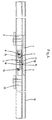
- the closing sequence control shown in FIG. 4 shows a trigger 14, the lever 16 of which is arranged pivotably about the axis of rotation 9 and on the one hand has the pawl 7 cooperating with the leaf spring 15 and movable about the pivot axis and on the other hand is provided with a roller.
- a sliding element 35 is connected to the passive leaf via a sliding arm, the role of the lever 16 interacting with a closed or almost closed passive leaf with an inclined surface 36 which is arranged on an extension of the sliding element 35.
- FIG. 5 shows a further embodiment in which the pawl 7 is mounted on a pivot axis 8 connected to the bearing part 13.
- This bearing part 13 is fastened in the upper chamber 11 of the slide rail 10 and forms a fastening point for a tension spring 38 acting on the pawl 7.
- a release lever 26 which carries a roller and thus acts on the passive leaf and is pivotably mounted on a pin 29 , attacks a pull cable 30 connected to the pawl 7.
- the pawl 7 when the tension spring 38 is tensioning, disengages from an active surface 37 attached to the slide 2, so that the slide 2 can move freely in the closing direction of the active leaf, ie the Active leaf can be closed automatically and comes into contact with the active leaf in the correct closing sequence.
- a shock absorber device (not shown here) can be located in the area of the slider 2 be arranged to the when the pawl 7 and To dampen effective area 37 occurring shocks.
- the slider 2 can for example in two parts with an intermediate elastic device, e.g. Spring device be trained.
- the trigger 14 which can be pivoted in the bearing part 13 about the axis of rotation 9 is designed as an angle lever 39 which carries a roller at its end opposite the axis of rotation 9 and thus acts on the passive leaf.
- An elongated hole device is arranged in the angle lever; this can be used to adjust the length of the angle lever and thus set the locking angle of the passive leaf.
- the sliding piece 2 connected to the active leaf is provided with an axial extension 42 which has an active surface 37.
- a latching block 41 which has an actuating surface 40 which interacts with the active surface 37, forms the latching element. If the passive leaf is still open, the closing movement of the active leaf ends at an opening angle which ensures that the passive leaf closes completely.
- a shock absorber device e.g. a spring device can be arranged which has a relative movement between slider 2 and effective area 37 when the Effective area 37 and actuating surface 40 allows.
- the exemplary embodiment in FIG. 7 is a modification compared to the example in FIG. 1.
- the modification consists in that the connecting part 5 has a shock absorber 70, which is connected to act between the slider 2 and the locking element 3.
- the shock absorber is a spring element consisting of one or more helical compression springs.
- the connecting part 5 is interrupted, ie it has a part 51 attached to the slider 2 and a part 52 arranged on the locking element 3.
- the shock absorber 70 is arranged between the mutually facing end faces of these parts 51, 52.
- the spring ends of the shock absorber spring or shock absorber springs are supported on the front ends of the parts 51, 52.
- the embodiment in FIG. 8 is a modification of the example in FIG. 7 insofar as the shock absorber 70 is modified. It has a spring assembly consisting of two helical compression springs 70a, 70b arranged parallel to one another, which are arranged in the same way as the shock absorber 70 in FIG. 7 between the ends of the connecting parts 51, 52 of the connecting element 5. In the same way as in Figure 7, the connecting parts 51, 52 are slidably guided in the upper chamber 11 of the slide rail 10.
- the shock absorber springs 70a, 70b are, however, each coupled to further helical compression springs 71a, 71b in the exemplary embodiment in FIG. 8.
- These further helical compression springs 71a, 71b represent a second spring assembly, which is arranged at the free end of the connecting part 5.
- the helical compression spring 71a is supported at one end at the free end of a push rod 72a which is screwed at the other end to the connecting part 51.
- the helical compression spring 71b is supported in a corresponding manner on the free end of a push rod 72b, which is also screwed to the connecting part 51 at its other end.
- the push rods 72a, 72b are arranged parallel to one another and run in the upper chamber 11 on both sides of the connecting part 52 and the locking element 3 arranged thereon.
- the other ends of the helical compression springs 71a, 71b are supported on an adjusting slide 73 which is in one with the free end Connecting part 52 fixedly connected carriage 74 is axially adjustable via an adjusting screw 75. If the slide 2 comes in the stop position of the locking element 6 when closing with the inactive leaf 21, ie when the contact surface 17 of the locking element 3 comes into contact with the surface 19 of the pawl 7, the springs 70a, 70b and 71a, 71b of the springs Shock absorber 70.
- the springs 70a, 70b are compressed by moving the connecting parts 51 and 52 towards one another and at the same time displacing the push rods 72a, 72b to the right toward the adjusting slide 73 while compressing the springs 71a, 71b.
- the connecting part 5, 51, 52 have a device for adjusting the length of the connecting part 5, 51, 52 can.
- This length adjustment device can e.g. an elongated hole in have at least one of the connecting parts 5, 51, 52 through which one Screw connection for fixing the connecting parts 5, 51, 52 passes through.
- the connecting part 5, 51, 52 can be modular be, depending on the installation situation different modular components of the Connecting part 5, 51, 52 combined and connected. Herewith is easy to adapt to the most diverse installation situations.
- the locking element 3 made of a material with a low Coefficient of friction can be formed, e.g. made of a plastic material.
- the locking element 3 can be used as a composite material element, preferably made of plastic and Metal or made of different plastics, preferably the surfaces interacting with the chamber 11, 12 of the slide rail 10 and / or points of the blocking element 3 made of plastic, preferably made of a Plastic with low coefficient of friction, and the corresponding with the pawl 7 Surfaces 17 and / or points of the blocking element 3 made of metal or a impact-resistant plastic. This arrangement combines the advantages of one low friction and wear.
- the dimensions of the locking element 3 and / or the arrangement of the depressions 4 in the locking element 3 so dimensioned are that the active leaf 20 is already in the fully open position is noticeable.
- This combines the advantages that, on the one hand, on the blocking element 3 no major impacts due to a rapidly closing active leaf 20 can act and on the other hand on an additional device for detection of the active leaf 20 in the open position, e.g. Electromagnet to be dispensed with can.
- All of the illustrated exemplary embodiments show a closing sequence control for consequent closing of a double-leaf door
- the door rebates in closed State are arranged one above the other so that the door rebate 23 of the Inactive leaf 21 forms the system for the door rebate 22 of the active leaf 20 and thus a tight closing of the door is guaranteed, as is the case for fire protection doors, for example is required.
- the closing sequence controls shown are simple in construction, enable easy installation and maintenance and are effective regardless of the attached or installed door closers, with great freedom of movement regarding the selection and arrangement of the door closers is guaranteed.
Landscapes
- Closing And Opening Devices For Wings, And Checks For Wings (AREA)
- Lock And Its Accessories (AREA)
- Operating, Guiding And Securing Of Roll- Type Closing Members (AREA)
- Support Devices For Sliding Doors (AREA)
Applications Claiming Priority (2)
| Application Number | Priority Date | Filing Date | Title |
|---|---|---|---|
| DE19951608A DE19951608A1 (de) | 1999-10-26 | 1999-10-26 | Schließfolgesteuerung mit vom Standflügel betätigter Sperreinrichtung |
| DE19951608 | 1999-10-26 |
Publications (3)
| Publication Number | Publication Date |
|---|---|
| EP1096088A2 true EP1096088A2 (fr) | 2001-05-02 |
| EP1096088A3 EP1096088A3 (fr) | 2001-05-30 |
| EP1096088B1 EP1096088B1 (fr) | 2004-04-21 |
Family
ID=7926962
Family Applications (1)
| Application Number | Title | Priority Date | Filing Date |
|---|---|---|---|
| EP00123078A Expired - Lifetime EP1096088B1 (fr) | 1999-10-26 | 2000-10-24 | Contrôle de fermeture ä séquence avec dispositif de verrouillage commandé par un battant stationnaire |
Country Status (3)
| Country | Link |
|---|---|
| EP (1) | EP1096088B1 (fr) |
| AT (1) | ATE264984T1 (fr) |
| DE (2) | DE19951608A1 (fr) |
Cited By (5)
| Publication number | Priority date | Publication date | Assignee | Title |
|---|---|---|---|---|
| WO2003029592A1 (fr) * | 2001-09-25 | 2003-04-10 | Dorma Gmbh + Co. Kg | Dispositif de commande de sequence de fermeture |
| EP1544396A1 (fr) * | 2003-12-18 | 2005-06-22 | GEZE GmbH | Coordinateur de fermeture de portes à double battants |
| DE102011057063A1 (de) | 2011-01-03 | 2012-07-05 | Walter Degelsegger | Vorrichtung für das Steuern der Schließfolge von zweiflügeligen Schwenktüren |
| AT507862B1 (de) * | 2009-01-16 | 2015-11-15 | Walter Ing Degelsegger | Vorrichtung für das steuern der schliessfolge von zweiflügeligen schwenktüren |
| AT14567U1 (de) * | 2011-11-16 | 2016-01-15 | Walter Ing Degelsegger | Vorrichtung für das Steuern der Schließfolge von zweiflügeligen Schwenktüren |
Families Citing this family (2)
| Publication number | Priority date | Publication date | Assignee | Title |
|---|---|---|---|---|
| EP3287722B1 (fr) | 2016-08-23 | 2020-07-15 | Dometic Sweden AB | Armoire pour véhicule de loisirs |
| DE102016216126A1 (de) | 2016-08-26 | 2018-03-01 | Dometic Sweden Ab | Kühleinrichtung für ein Freizeitfahrzeug |
Citations (7)
| Publication number | Priority date | Publication date | Assignee | Title |
|---|---|---|---|---|
| GB2058204A (en) * | 1979-07-31 | 1981-04-08 | Dixon M G | Timed door control |
| DE3336739A1 (de) * | 1983-10-08 | 1985-04-25 | Dorma-Baubeschlag Gmbh & Co Kg, 5828 Ennepetal | Schliessfolgevorrichtung fuer eine zweifluegelige tuer |
| DE3609565A1 (de) * | 1986-03-21 | 1987-09-24 | Dorma Gmbh & Co Kg | Schliessfolgeregelvorrichtung fuer eine zweifluegelige tuer |
| DE3806662A1 (de) * | 1987-03-05 | 1988-09-15 | Geze Grundstueck Beteiligung | Feststellvorrichtung fuer eine mit einem tuerschliesser versehene tuer |
| EP0356728A1 (fr) * | 1988-08-17 | 1990-03-07 | Gretsch-Unitas GmbH Baubeschläge | Dispositif de commande de la séquence de fermeture de portes à doubles battants |
| DE4308560A1 (de) * | 1993-03-18 | 1994-09-22 | Dorma Gmbh & Co Kg | Schließfolgeregelung für eine über Türschließer selbstschließende, einen Standflügel und einen Gangflügel umfassende Tür |
| DE19545402A1 (de) * | 1995-12-06 | 1997-06-12 | Geze Gmbh & Co | Schließfolgesteuerung für eine automatisch schließende, zweiflügelige Tür |
Family Cites Families (3)
| Publication number | Priority date | Publication date | Assignee | Title |
|---|---|---|---|---|
| DE3612917A1 (de) * | 1986-04-17 | 1987-10-22 | Dorma Gmbh & Co Kg | Schliessfolgeregelvorrichtung fuer eine zweifluegelige tuer |
| US5483769A (en) * | 1993-12-07 | 1996-01-16 | Mark Iv Transportation Products Corporation | Door drive equipment for mass transit vehicle |
| DE19644485B4 (de) * | 1996-10-25 | 2008-07-24 | Geze Gmbh | Verriegelungsvorrichtung für eine Schiebetür |
-
1999
- 1999-10-26 DE DE19951608A patent/DE19951608A1/de not_active Withdrawn
-
2000
- 2000-10-24 AT AT00123078T patent/ATE264984T1/de not_active IP Right Cessation
- 2000-10-24 DE DE50006134T patent/DE50006134D1/de not_active Expired - Lifetime
- 2000-10-24 EP EP00123078A patent/EP1096088B1/fr not_active Expired - Lifetime
Patent Citations (8)
| Publication number | Priority date | Publication date | Assignee | Title |
|---|---|---|---|---|
| GB2058204A (en) * | 1979-07-31 | 1981-04-08 | Dixon M G | Timed door control |
| DE3336739A1 (de) * | 1983-10-08 | 1985-04-25 | Dorma-Baubeschlag Gmbh & Co Kg, 5828 Ennepetal | Schliessfolgevorrichtung fuer eine zweifluegelige tuer |
| DE3609565A1 (de) * | 1986-03-21 | 1987-09-24 | Dorma Gmbh & Co Kg | Schliessfolgeregelvorrichtung fuer eine zweifluegelige tuer |
| DE3806662A1 (de) * | 1987-03-05 | 1988-09-15 | Geze Grundstueck Beteiligung | Feststellvorrichtung fuer eine mit einem tuerschliesser versehene tuer |
| EP0356728A1 (fr) * | 1988-08-17 | 1990-03-07 | Gretsch-Unitas GmbH Baubeschläge | Dispositif de commande de la séquence de fermeture de portes à doubles battants |
| US4967512A (en) * | 1988-08-17 | 1990-11-06 | Gretsch-Unitas Gmbh Baubeschlage | Arrangement for controlling the closing sequence of two wings of a door, window or the like |
| DE4308560A1 (de) * | 1993-03-18 | 1994-09-22 | Dorma Gmbh & Co Kg | Schließfolgeregelung für eine über Türschließer selbstschließende, einen Standflügel und einen Gangflügel umfassende Tür |
| DE19545402A1 (de) * | 1995-12-06 | 1997-06-12 | Geze Gmbh & Co | Schließfolgesteuerung für eine automatisch schließende, zweiflügelige Tür |
Cited By (8)
| Publication number | Priority date | Publication date | Assignee | Title |
|---|---|---|---|---|
| WO2003029592A1 (fr) * | 2001-09-25 | 2003-04-10 | Dorma Gmbh + Co. Kg | Dispositif de commande de sequence de fermeture |
| EP1544396A1 (fr) * | 2003-12-18 | 2005-06-22 | GEZE GmbH | Coordinateur de fermeture de portes à double battants |
| AT507862B1 (de) * | 2009-01-16 | 2015-11-15 | Walter Ing Degelsegger | Vorrichtung für das steuern der schliessfolge von zweiflügeligen schwenktüren |
| DE102011057063A1 (de) | 2011-01-03 | 2012-07-05 | Walter Degelsegger | Vorrichtung für das Steuern der Schließfolge von zweiflügeligen Schwenktüren |
| AT510907A1 (de) * | 2011-01-03 | 2012-07-15 | Walter Ing Degelsegger | Vorrichtung für das steuern der schliessfolge von zweiflügeligen schwenktüren |
| AT510907B1 (de) * | 2011-01-03 | 2013-01-15 | Walter Ing Degelsegger | Vorrichtung für das steuern der schliessfolge von zweiflügeligen schwenktüren |
| DE102011057063B4 (de) * | 2011-01-03 | 2017-04-06 | Walter Degelsegger | Vorrichtung für das Steuern der Schließfolge von zweiflügeligen Schwenktüren |
| AT14567U1 (de) * | 2011-11-16 | 2016-01-15 | Walter Ing Degelsegger | Vorrichtung für das Steuern der Schließfolge von zweiflügeligen Schwenktüren |
Also Published As
| Publication number | Publication date |
|---|---|
| ATE264984T1 (de) | 2004-05-15 |
| EP1096088B1 (fr) | 2004-04-21 |
| DE19951608A1 (de) | 2001-05-03 |
| DE50006134D1 (de) | 2004-05-27 |
| EP1096088A3 (fr) | 2001-05-30 |
Similar Documents
| Publication | Publication Date | Title |
|---|---|---|
| AT511546B1 (de) | Möbelantrieb für eine bewegbare möbelklappe | |
| EP1314842A1 (fr) | Dispositif d'ouverture et de fermeture pour une partie de meuble mobile | |
| EP2746503A2 (fr) | Serrure de véhicule automobile | |
| EP1837472B1 (fr) | Fenêtre, porte ou similaire avec un dispositif de délestage | |
| DE202005015166U1 (de) | Schwenkschiebetür für Fahrzeuge, insbesondere Fahrgasttür für Fahrzeuge des öffentlichen Personennahverkehrs | |
| EP1096088B1 (fr) | Contrôle de fermeture ä séquence avec dispositif de verrouillage commandé par un battant stationnaire | |
| EP2169160B1 (fr) | Dispositif de fixation pour un battant de porte | |
| WO2007009902A1 (fr) | Mecanisme d'amortissement | |
| EP3417134B1 (fr) | Ensemble ferrure pour le raccordement d'un battant coulissant et basculant | |
| EP2871312B1 (fr) | Dispositif d'aération par entrebâillement pour porte ou fenêtre coulissante et porte ou fenêtre coulissante | |
| DE10122817B4 (de) | Vorrichtung zur Schließfolgeregelung | |
| EP3752700A1 (fr) | Dispositif anti-effraction abaissable | |
| DE102008013494B4 (de) | Türschließer | |
| DE19545402A1 (de) | Schließfolgesteuerung für eine automatisch schließende, zweiflügelige Tür | |
| DE102017115823A1 (de) | Beschlag für einen kipp- und schiebbaren Flügel und Verfahren zum Öffnen und Schließen eines parallel abstellbaren und verschiebbaren Flügels | |
| EP0985794A2 (fr) | Commande pour l'ouvrant d'une porte , d'une fenêtre ou similaire | |
| EP2818618B1 (fr) | Dispositif de régulation de la séquence de fermeture d'une installation de porte rotative à deux battants | |
| EP3243989B1 (fr) | Système de ferrure | |
| EP2511463B1 (fr) | Fenêtre, porte ou analogue pourvue d'un dispositif d'amortissement | |
| EP1544398B1 (fr) | Dispositif coordonnateur de fermeture pour portes à deux vantaux | |
| EP1801337B1 (fr) | Dispositif de commande de la séquence de fermeture de portes à deux battants | |
| DE19605586A1 (de) | Vorrichtung zur Schließfolgesteuerung für zweiflügelige Türen, insbesondere für Feuerschutztüren | |
| DE10360036B4 (de) | Vorrichtung zur Schließfolgeregelung | |
| DE10360039B4 (de) | Vorrichtung zur Schließfolgeregelung für zweiflügelige Drehtüren | |
| DE3701300A1 (de) | Tuerschliesser |
Legal Events
| Date | Code | Title | Description |
|---|---|---|---|
| PUAI | Public reference made under article 153(3) epc to a published international application that has entered the european phase |
Free format text: ORIGINAL CODE: 0009012 |
|
| PUAL | Search report despatched |
Free format text: ORIGINAL CODE: 0009013 |
|
| AK | Designated contracting states |
Kind code of ref document: A2 Designated state(s): AT BE CH CY DE DK ES FI FR GB GR IE IT LI LU MC NL PT SE |
|
| AX | Request for extension of the european patent |
Free format text: AL;LT;LV;MK;RO;SI |
|
| AK | Designated contracting states |
Kind code of ref document: A3 Designated state(s): AT BE CH CY DE DK ES FI FR GB GR IE IT LI LU MC NL PT SE |
|
| AX | Request for extension of the european patent |
Free format text: AL;LT;LV;MK;RO;SI |
|
| 17P | Request for examination filed |
Effective date: 20010621 |
|
| AKX | Designation fees paid |
Free format text: AT BE CH CY DE DK ES FI FR GB GR IE IT LI LU MC NL PT SE |
|
| GRAP | Despatch of communication of intention to grant a patent |
Free format text: ORIGINAL CODE: EPIDOSNIGR1 |
|
| GRAS | Grant fee paid |
Free format text: ORIGINAL CODE: EPIDOSNIGR3 |
|
| GRAA | (expected) grant |
Free format text: ORIGINAL CODE: 0009210 |
|
| AK | Designated contracting states |
Kind code of ref document: B1 Designated state(s): AT BE CH CY DE DK ES FI FR GB GR IE IT LI LU MC NL PT SE |
|
| PG25 | Lapsed in a contracting state [announced via postgrant information from national office to epo] |
Ref country code: IT Free format text: LAPSE BECAUSE OF FAILURE TO SUBMIT A TRANSLATION OF THE DESCRIPTION OR TO PAY THE FEE WITHIN THE PRE;WARNING: LAPSES OF ITALIAN PATENTS WITH EFFECTIVE DATE BEFORE 2007 MAY HAVE OCCURRED AT ANY TIME BEFORE 2007. THE CORRECT EFFECTIVE DATE MAY BE DIFFERENT FROM THE ONE RECORDED.SCRIBED TIME-LIMIT Effective date: 20040421 Ref country code: FR Free format text: LAPSE BECAUSE OF FAILURE TO SUBMIT A TRANSLATION OF THE DESCRIPTION OR TO PAY THE FEE WITHIN THE PRESCRIBED TIME-LIMIT Effective date: 20040421 Ref country code: GB Free format text: LAPSE BECAUSE OF FAILURE TO SUBMIT A TRANSLATION OF THE DESCRIPTION OR TO PAY THE FEE WITHIN THE PRESCRIBED TIME-LIMIT Effective date: 20040421 Ref country code: FI Free format text: LAPSE BECAUSE OF FAILURE TO SUBMIT A TRANSLATION OF THE DESCRIPTION OR TO PAY THE FEE WITHIN THE PRESCRIBED TIME-LIMIT Effective date: 20040421 Ref country code: IE Free format text: LAPSE BECAUSE OF FAILURE TO SUBMIT A TRANSLATION OF THE DESCRIPTION OR TO PAY THE FEE WITHIN THE PRESCRIBED TIME-LIMIT Effective date: 20040421 Ref country code: NL Free format text: LAPSE BECAUSE OF FAILURE TO SUBMIT A TRANSLATION OF THE DESCRIPTION OR TO PAY THE FEE WITHIN THE PRESCRIBED TIME-LIMIT Effective date: 20040421 Ref country code: CY Free format text: LAPSE BECAUSE OF FAILURE TO SUBMIT A TRANSLATION OF THE DESCRIPTION OR TO PAY THE FEE WITHIN THE PRESCRIBED TIME-LIMIT Effective date: 20040421 |
|
| REG | Reference to a national code |
Ref country code: GB Ref legal event code: FG4D Free format text: NOT ENGLISH |
|
| REG | Reference to a national code |
Ref country code: CH Ref legal event code: EP |
|
| REG | Reference to a national code |
Ref country code: IE Ref legal event code: FG4D Free format text: GERMAN |
|
| REF | Corresponds to: |
Ref document number: 50006134 Country of ref document: DE Date of ref document: 20040527 Kind code of ref document: P |
|
| PG25 | Lapsed in a contracting state [announced via postgrant information from national office to epo] |
Ref country code: SE Free format text: LAPSE BECAUSE OF FAILURE TO SUBMIT A TRANSLATION OF THE DESCRIPTION OR TO PAY THE FEE WITHIN THE PRESCRIBED TIME-LIMIT Effective date: 20040721 Ref country code: GR Free format text: LAPSE BECAUSE OF FAILURE TO SUBMIT A TRANSLATION OF THE DESCRIPTION OR TO PAY THE FEE WITHIN THE PRESCRIBED TIME-LIMIT Effective date: 20040721 Ref country code: DK Free format text: LAPSE BECAUSE OF FAILURE TO SUBMIT A TRANSLATION OF THE DESCRIPTION OR TO PAY THE FEE WITHIN THE PRESCRIBED TIME-LIMIT Effective date: 20040721 |
|
| PG25 | Lapsed in a contracting state [announced via postgrant information from national office to epo] |
Ref country code: ES Free format text: LAPSE BECAUSE OF FAILURE TO SUBMIT A TRANSLATION OF THE DESCRIPTION OR TO PAY THE FEE WITHIN THE PRESCRIBED TIME-LIMIT Effective date: 20040801 |
|
| NLV1 | Nl: lapsed or annulled due to failure to fulfill the requirements of art. 29p and 29m of the patents act | ||
| GBV | Gb: ep patent (uk) treated as always having been void in accordance with gb section 77(7)/1977 [no translation filed] |
Effective date: 20040421 |
|
| PG25 | Lapsed in a contracting state [announced via postgrant information from national office to epo] |
Ref country code: LU Free format text: LAPSE BECAUSE OF NON-PAYMENT OF DUE FEES Effective date: 20041024 Ref country code: AT Free format text: LAPSE BECAUSE OF NON-PAYMENT OF DUE FEES Effective date: 20041024 |
|
| PG25 | Lapsed in a contracting state [announced via postgrant information from national office to epo] |
Ref country code: CH Free format text: LAPSE BECAUSE OF NON-PAYMENT OF DUE FEES Effective date: 20041031 Ref country code: BE Free format text: LAPSE BECAUSE OF NON-PAYMENT OF DUE FEES Effective date: 20041031 Ref country code: MC Free format text: LAPSE BECAUSE OF NON-PAYMENT OF DUE FEES Effective date: 20041031 Ref country code: LI Free format text: LAPSE BECAUSE OF NON-PAYMENT OF DUE FEES Effective date: 20041031 |
|
| REG | Reference to a national code |
Ref country code: IE Ref legal event code: FD4D |
|
| PLBE | No opposition filed within time limit |
Free format text: ORIGINAL CODE: 0009261 |
|
| STAA | Information on the status of an ep patent application or granted ep patent |
Free format text: STATUS: NO OPPOSITION FILED WITHIN TIME LIMIT |
|
| EN | Fr: translation not filed | ||
| 26N | No opposition filed |
Effective date: 20050124 |
|
| BERE | Be: lapsed |
Owner name: *GEZE G.M.B.H. Effective date: 20041031 |
|
| REG | Reference to a national code |
Ref country code: CH Ref legal event code: PL |
|
| BERE | Be: lapsed |
Owner name: *GEZE G.M.B.H. Effective date: 20041031 |
|
| PG25 | Lapsed in a contracting state [announced via postgrant information from national office to epo] |
Ref country code: PT Free format text: LAPSE BECAUSE OF NON-PAYMENT OF DUE FEES Effective date: 20040921 |
|
| PGFP | Annual fee paid to national office [announced via postgrant information from national office to epo] |
Ref country code: DE Payment date: 20181031 Year of fee payment: 19 |
|
| REG | Reference to a national code |
Ref country code: DE Ref legal event code: R231 Ref document number: 50006134 Country of ref document: DE |
|
| PG25 | Lapsed in a contracting state [announced via postgrant information from national office to epo] |
Ref country code: DE Free format text: LAPSE BECAUSE OF THE APPLICANT RENOUNCES Effective date: 20190925 |