EP1096088A2 - Closing sequence control with a locking device activated by a standing panel - Google Patents
Closing sequence control with a locking device activated by a standing panel Download PDFInfo
- Publication number
- EP1096088A2 EP1096088A2 EP00123078A EP00123078A EP1096088A2 EP 1096088 A2 EP1096088 A2 EP 1096088A2 EP 00123078 A EP00123078 A EP 00123078A EP 00123078 A EP00123078 A EP 00123078A EP 1096088 A2 EP1096088 A2 EP 1096088A2
- Authority
- EP
- European Patent Office
- Prior art keywords
- leaf
- sequence control
- control according
- closing sequence
- pawl
- Prior art date
- Legal status (The legal status is an assumption and is not a legal conclusion. Google has not performed a legal analysis and makes no representation as to the accuracy of the status listed.)
- Granted
Links
Images


Classifications
-
- E—FIXED CONSTRUCTIONS
- E05—LOCKS; KEYS; WINDOW OR DOOR FITTINGS; SAFES
- E05F—DEVICES FOR MOVING WINGS INTO OPEN OR CLOSED POSITION; CHECKS FOR WINGS; WING FITTINGS NOT OTHERWISE PROVIDED FOR, CONCERNED WITH THE FUNCTIONING OF THE WING
- E05F5/00—Braking devices, e.g. checks; Stops; Buffers
- E05F5/12—Braking devices, e.g. checks; Stops; Buffers specially for preventing the closing of a wing before another wing has been closed
Definitions
- the invention relates to a closing sequence control for a door closer automatically closing, double-leaf door according to the preamble of the claim 1.
- Closing sequence controls are required for double-leaf doors, if at tightly closing doors overlap the door leaves in the middle with door rebates. At such doors, the passive leaf forms a stop for the active leaf, so that the active leaf always lies against the passive leaf when the door is closed. Accordingly the passive leaf must always be closed during the closing process, before the active leaf executes at least the end of the closing path.
- the closing sequence control is required so that the right one for fire protection doors, for example Closing sequence of passive leaf and active leaf, i.e. the logical closing the double-leaf door.
- a closing sequence control corresponding to the preamble of claim 1 is known from DE 43 08 560 A1, in which the two-leaf door is a passive leaf and has an active leaf, the closing process for the active leaf can only be fully executed when the inactive leaf is closed.
- This is a locking device is provided which with a sliding arm on the active leaf a slide arranged in a slide acts. From the inactive leaf via a control lever and a thrust member provided with a saw toothing Locking element actuated, the thrust member over the axial movement Converted inclined surfaces into a vertical movement for the locking element and thereby the locking element interact with the saw teeth of the slider can.
- This locking element is under the action of vertically acting pressure springs and is only vertically movable, making a violent impact on the active leaf Closing force exerted as a result of the saw teeth as uncontrollable high force acts on the locking device.
- the structure of the locking device corresponds the closing sequence control according to DE 33 36 739 C2. This also points here Slider on its top has a serration, while that of Inactive leaf operated pushing element moves the locking element vertically.
- This Latching element has a serration on its underside, which by Thrust member to be engaged in the saw teeth of the slider can, if the passive leaf is not yet closed. Will open Inactive leaf exerts an opening force on the active leaf, so it can be skipped the serration of the active leaf can be opened further.
- the wing according to EP 0 356 728 B1 becomes a locking device with a sawtooth Locking side used, with a tooth in the toothing Can engage locking part, while this locking part can be actuated via a sliding roller is and this slide roller on a slide arm one connected to the passive leaf Door closer is arranged.
- This locking device stands over a sliding link and a coupling rod with one cooperating with the active leaf Locking member in operative connection, this locking member being crescent-shaped and by pivoting it ensures that when the passive leaf is open the active leaf cannot be closed completely.
- the locking member acts for this purpose together with a sliding roller of the door closer assigned to the active leaf.
- the sliding member mentioned consists essentially of two in extension mutually arranged sliding link parts that are coupled together are.
- the entire device for controlling the closing sequence of the door leaves consists of a large number of sometimes complicated components that are complex are to be produced. In addition to the high construction costs, assembly is also complicated, so that such a construction is very expensive and maintenance only can be done by appropriately trained personnel.
- the object of the present invention is to provide a closing sequence control to create a locking device operated by the passive leaf, which is easy in the Structure and has a problem-free assembly and maintenance.
- the one to block the closing movement of the active leaf when not closed The provided locking device exists according to the present Invention from a locking element cooperating with the locking element, this locking element is angularly movable with an articulated in the slide rail mounted trigger or can be moved at an angle with the slide rail stands and is arranged to engage in recesses of the locking element.
- Such Locking device is independent of the design and arrangement of the door closers applicable for the active and active leaf and is due to their simple Design inexpensive to manufacture and allows easy Assembly and maintenance. This applies particularly to the embodiments in which the locking element by a pawl rotatably arranged about a pivot axis is formed and this pawl with contact surfaces of the recesses of the locking element is arranged cooperatively. But it is also possible to open the jack to attach a trigger that is pivotally mounted about an axis of rotation.
- One of the two contact surfaces of the depressions of the locking element does not exercise closed passive leaf that starts in the closing direction from the active leaf Closing force on the latch. So that the trigger with the active leaf open cannot be pressed out of the locked position when on by a person A closing force is exerted on the active leaf is the slope of the contact surface of the locking element so that the closing force has a line of action, which ideally runs through the axis of rotation of the trigger is.
- there is some friction between the corresponding surfaces the pawl and the locking element must be overcome, it makes sense to to arrange corresponding surfaces of the pawl and the locking element so that the effective force of the closing force is slightly below the axis of rotation of the trigger runs.
- the other of the two contact surfaces exercises when the locking device acts and an opening movement of the active leaf exerts a force on the pawl, the causes a stroke and / or angular movement of the pawl and thus a small Opening force is sufficient to overcome the locking device. If applicable the arrangement of a return spring is conceivable, which the trigger in the locked position acted upon.
- very simple embodiments are created when the jack is arranged with its pivot axis on a lever of a trigger and the Lever around one in the slide rail or one firmly connected to the slide rail Bearing part is pivotally mounted about an axis of rotation.
- the slide piece assigned to the active leaf in the lower chamber of the slide rail arranged and stands with that in the upper chamber of the slide rail located locking element in connection, while the trigger with the locking element is arranged essentially in the lower chamber of the slide rail.
- the bearing part receiving the locking lever is preferably a positive fit in the relevant chamber of the slide rail and thus serves in Case that two separate slide rails are used for active leaf and passive leaf be used as a coupling between the slide rails.
- the connecting part can be easily Way to include a shock absorber or formed by a shock absorber be effective between the slider and the locking element and in particular the heavy leaf that may occur during the closing movement absorbs high kinetic energy.
- the shock absorber can be used as a helical compression spring device be trained, alternatively or additionally but also other designs of the shock absorber, such as elastically deformable Molded bodies or pneumatically / hydraulically functioning devices, into consideration.
- the Trigger designed as an articulated lever, which has an articulated lever piece, the on the one hand is mounted on a mounting axis and on the other hand carries the pivot axis for the pawl and with this pivot axis in one Elongated hole of the lever forming the trigger engages.
- a different one Execution with a pull rope is obtained by the fact that the pawl carrying Trigger is designed as a lever loaded by a return spring, which in a bearing part fastened in the lower chamber of the slide rail about the axis of rotation is pivotally mounted and preferably over a component that is subjected to tension a Bowden cable, with one interacting with the passive leaf Release lever is in operative connection.
- a return spring which in a bearing part fastened in the lower chamber of the slide rail about the axis of rotation is pivotally mounted and preferably over a component that is subjected to tension a Bowden cable, with one interacting with the passive leaf Release lever is in operative connection.
- These versions can also between the slider and the locking element easily in if necessary
- Train direction acting shock absorbers are installed, for example a Has tension spring, the spring movements are damped.
- the Bowden cable can itself be designed to be elastically deformable, around the heavy leaf that may occur during the closing movement absorb high kinetic energy.
- the one carrying the latch acts Lever with one operated from the passive leaf and arranged in the slide rail Sliding element together.
- the one assigned to the passive leaf Sliding element with an inclined surface, which when closed or almost closed inactive leaf with the end of the trigger Lever interacts.
- An embodiment is formed in that the locking element, preferably the Jack, is arranged in the upper chamber of the slide rail and over one Train-stressed component, for example a pull rope, with one with the Inactive leaf interacting trigger lever is connected during the Slider has an obliquely running effective surface that with the pawl cooperates. So with a strong closing force acting on the active leaf no components are damaged, either the effective surface is inclined so that the latch slides on it with large closing forces and an angular movement executes, or the pivot axis of the pawl is in one with the Sliding rail connected bearing part vertically displaceable against a spring force arranged.
- Train-stressed component for example a pull rope
- the closing sequence control to cover the door leaves and the arrangement of the door hinges is the locking block provided with an actuating surface the angle lever is arranged adjustable and comes on an effective surface an axial extension of the slider assigned to the active leaf Investment.
- the active leaf is with a sliding arm door closer and the passive leaf is equipped with a sliding arm door closer.
- the one in the slide rail of the sliding arm of the sliding door closer is with one Locking element connected.
- the sliding rail of the active leaf door closer and the Slide rail of the leaf door closer can be in a common at the top horizontal spar of the fixed frame arranged continuous Slide rail be formed.
- the actuation of the arranged in the slide rail Locking element can be made directly or indirectly from the passive leaf.
- the door closers can be surface-mounted or, in the case of advantageous designs, in the door frame be integrated.
- the slide rails can also lie on top or can be arranged integrated in the door frame in advantageous embodiments.
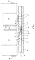
- a active leaf 20 that can be pivoted about a door hinge 24 and a passive leaf 21 that can be pivoted about a door hinge 25 is arranged, with a locking device being provided that, when the active leaf 21 is open, the closing movement of the active leaf 20 blocked so that the door rebates 22, 23 overlap when the door is closed so that the door rebate 23 of the passive leaf 21 forms the stop for the door rebate 22 of the active leaf.
- the passive leaf 21 and the active leaf 20 are each equipped with a door closer, not shown. It can be a sliding arm door closer.
- the fixed leaf 21 is shown in a still open position and the active leaf 20 in a position blocked by the locking device, the smallest has a lockable opening angle that still closes properly of the passive leaf 21 guaranteed.
- This smallest blockable opening angle of the active leaf 20 is dependent on the coverage width of the door rebate 22 and 23 and the arrangement of the door hinges 24, 25.
- the locking device points a sliding arm 1 on the one hand with the active leaf 20 and on the other hand with a slider 2 is articulated. Between the slider 2 and one Locking element 3 is a connecting part 5, for example a (here not shown) absorbs shock absorbers or even designed as shock absorbers is.
- the locking element 3 has axially one behind the other and preferably sawtooth-shaped recesses 4, in which a locking element 6 engages, this, for example, by an angularly movable about a pivot axis 8 Jack 7 is formed.
- a trigger 14 is provided with a lever 16 which is on an axis of rotation 9 arranged in a bearing part 13 is supported and on the one hand a leaf spring 15 acting on the pawl 7 and on the other hand one from the passive leaf 21 actuated role carries.
- the parts of the closing sequence control are located essentially in a slide rail 10 with an upper chamber 11 and lower chamber 12. In the upper chamber 11 that slides with the active leaf 20th related locking element 3 and the lower chamber 12 essentially takes the locking element 6 and the trigger 14.
- a surface 19 of the pawl 7 acts in the closing direction of the active leaf 20 with a relative to the direction of movement the slider steeper contact surface 17 of the locking element 3 together, while during the opening movement of the active leaf 20 a relative to the direction of movement the slider flat contact surface 18 acts on the pawl 7.
- the Slide rail 10 can be designed as a slide rail of slide arm door closers.
- the sliding arm 1 can be designed as a sliding arm of the leaf door closer.
- the housing of the active leaf door closer can be mounted on the active leaf his.
- the closing sequence control shown in FIG. 1 has a partially open position of the passive leaf 21 and active leaf 20, the active leaf 20 being held in the position by the locking device which corresponds to the smallest opening angle, so that the fixed leaf 21 can still be closed properly.
- the pawl 7 interacts with the last left recess 4 of the locking element 3 and lies with the surface 19 on the contact surface 17 acting in the closing direction.
- the closing force exerted on the active leaf 20 by the non-illustrated active leaf door closer is rotatable via the active leaf and the Transfer slide 2 connected slide arm 1 to the locking device. This closing force exerted by the active leaf door closer is considerably smaller than the holding force exerted by the locking device for the active leaf 21 when the passive leaf 21 is not closed.
- the locking element 3 is designed so long that the outermost recess 4 (on the right in the drawing) then with the latch 7 interacts when the active leaf 2 is fully open, thereby ensuring that the active leaf 2 is blocked even at large opening angles, and it is thus avoided that the locking element 3 strikes the pawl 7 at high speed, ie with high kinetic energy.
- Another opening of the active leaf 20 when the door is not closed Inactive leaf is possible in that the contact surface acting in the opening direction 18 of the locking element 3 presses the pawl and thereby the lever 16 pivots about the axis of rotation 9 and the axial movement of the locking element 3 releases.
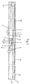
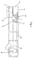
- FIG. 2 shows an embodiment of the closing sequence control without the two-leaf door.
- the slider 2 which is displaceable in the lower chamber 12 of the slide rail 10 and which is connected in an articulated manner to the slide arm 1 engaging on the active leaf, is fastened via a traction cable 30 and a deflection roller 32 to the locking element 3 which can be displaced in the upper chamber 11 of the slide rail 10.
- a tensioning device acts, which consists of a tension spring 31, for example, in the form of a rubber or elastomer rope.
- the trigger 14 has an articulated lever which has an articulated lever piece 33 which is mounted on the one hand on a fastening axis 34 and on the other hand carries the pivot axis 8 for the pawl 7.
- the leaf spring 15 cooperating with the pawl 7 is fastened to the articulated lever piece 33.
- the articulated lever piece 33 engages in an elongated hole in the lever 16 which is pivotable about the axis of rotation 9. Since the locking element 3 is subjected to tension in the closing direction of the active leaf when the inactive leaf is not or not completely closed, the contact surface 17 acts on the pawl 7 in this direction, while in the opening direction of the active leaf the contact surface 18 acts on the pawl 7 and presses it downward .
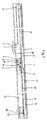
- FIG. 3 differs from that of FIG. 2 essentially by a different type of trigger 14 and its connection to a release lever 26 which can be actuated by the passive leaf.
- This connection is made by a Bowden cable 28 which, on the one hand, is connected to the release lever 26 which can be pivoted about a bolt 29 is attached and on the other hand is connected in such a way to the pivotable lever 16 about the axis of rotation 9 that when the inactive leaf acts on the roller of the release lever 26, the lever 16 is pivoted against the force of a return spring 27 about the axis of rotation and thereby the pawl mounted on the pivot axis 8 is led down.
- the other reference numerals shown in this figure correspond to those in FIG. 2 in terms of structure and mode of operation.
- a shock absorber device (not shown here) is arranged in the region of the pull cable 30 can be the when the pawl 7 meets the contact surface 17 dampen shocks. Alternatively or additionally, this can also be done Traction rope 30 can be designed as an elastic element.
- pull rope 30 is also an alternative a belt, a belt, a chain or the like is conceivable.
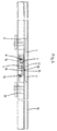
- the closing sequence control shown in FIG. 4 shows a trigger 14, the lever 16 of which is arranged pivotably about the axis of rotation 9 and on the one hand has the pawl 7 cooperating with the leaf spring 15 and movable about the pivot axis and on the other hand is provided with a roller.
- a sliding element 35 is connected to the passive leaf via a sliding arm, the role of the lever 16 interacting with a closed or almost closed passive leaf with an inclined surface 36 which is arranged on an extension of the sliding element 35.
- FIG. 5 shows a further embodiment in which the pawl 7 is mounted on a pivot axis 8 connected to the bearing part 13.
- This bearing part 13 is fastened in the upper chamber 11 of the slide rail 10 and forms a fastening point for a tension spring 38 acting on the pawl 7.
- a release lever 26 which carries a roller and thus acts on the passive leaf and is pivotably mounted on a pin 29 , attacks a pull cable 30 connected to the pawl 7.
- the pawl 7 when the tension spring 38 is tensioning, disengages from an active surface 37 attached to the slide 2, so that the slide 2 can move freely in the closing direction of the active leaf, ie the Active leaf can be closed automatically and comes into contact with the active leaf in the correct closing sequence.
- a shock absorber device (not shown here) can be located in the area of the slider 2 be arranged to the when the pawl 7 and To dampen effective area 37 occurring shocks.
- the slider 2 can for example in two parts with an intermediate elastic device, e.g. Spring device be trained.
- the trigger 14 which can be pivoted in the bearing part 13 about the axis of rotation 9 is designed as an angle lever 39 which carries a roller at its end opposite the axis of rotation 9 and thus acts on the passive leaf.
- An elongated hole device is arranged in the angle lever; this can be used to adjust the length of the angle lever and thus set the locking angle of the passive leaf.
- the sliding piece 2 connected to the active leaf is provided with an axial extension 42 which has an active surface 37.
- a latching block 41 which has an actuating surface 40 which interacts with the active surface 37, forms the latching element. If the passive leaf is still open, the closing movement of the active leaf ends at an opening angle which ensures that the passive leaf closes completely.
- a shock absorber device e.g. a spring device can be arranged which has a relative movement between slider 2 and effective area 37 when the Effective area 37 and actuating surface 40 allows.
- the exemplary embodiment in FIG. 7 is a modification compared to the example in FIG. 1.
- the modification consists in that the connecting part 5 has a shock absorber 70, which is connected to act between the slider 2 and the locking element 3.
- the shock absorber is a spring element consisting of one or more helical compression springs.
- the connecting part 5 is interrupted, ie it has a part 51 attached to the slider 2 and a part 52 arranged on the locking element 3.
- the shock absorber 70 is arranged between the mutually facing end faces of these parts 51, 52.
- the spring ends of the shock absorber spring or shock absorber springs are supported on the front ends of the parts 51, 52.
- the embodiment in FIG. 8 is a modification of the example in FIG. 7 insofar as the shock absorber 70 is modified. It has a spring assembly consisting of two helical compression springs 70a, 70b arranged parallel to one another, which are arranged in the same way as the shock absorber 70 in FIG. 7 between the ends of the connecting parts 51, 52 of the connecting element 5. In the same way as in Figure 7, the connecting parts 51, 52 are slidably guided in the upper chamber 11 of the slide rail 10.
- the shock absorber springs 70a, 70b are, however, each coupled to further helical compression springs 71a, 71b in the exemplary embodiment in FIG. 8.
- These further helical compression springs 71a, 71b represent a second spring assembly, which is arranged at the free end of the connecting part 5.
- the helical compression spring 71a is supported at one end at the free end of a push rod 72a which is screwed at the other end to the connecting part 51.
- the helical compression spring 71b is supported in a corresponding manner on the free end of a push rod 72b, which is also screwed to the connecting part 51 at its other end.
- the push rods 72a, 72b are arranged parallel to one another and run in the upper chamber 11 on both sides of the connecting part 52 and the locking element 3 arranged thereon.
- the other ends of the helical compression springs 71a, 71b are supported on an adjusting slide 73 which is in one with the free end Connecting part 52 fixedly connected carriage 74 is axially adjustable via an adjusting screw 75. If the slide 2 comes in the stop position of the locking element 6 when closing with the inactive leaf 21, ie when the contact surface 17 of the locking element 3 comes into contact with the surface 19 of the pawl 7, the springs 70a, 70b and 71a, 71b of the springs Shock absorber 70.
- the springs 70a, 70b are compressed by moving the connecting parts 51 and 52 towards one another and at the same time displacing the push rods 72a, 72b to the right toward the adjusting slide 73 while compressing the springs 71a, 71b.
- the connecting part 5, 51, 52 have a device for adjusting the length of the connecting part 5, 51, 52 can.
- This length adjustment device can e.g. an elongated hole in have at least one of the connecting parts 5, 51, 52 through which one Screw connection for fixing the connecting parts 5, 51, 52 passes through.
- the connecting part 5, 51, 52 can be modular be, depending on the installation situation different modular components of the Connecting part 5, 51, 52 combined and connected. Herewith is easy to adapt to the most diverse installation situations.
- the locking element 3 made of a material with a low Coefficient of friction can be formed, e.g. made of a plastic material.
- the locking element 3 can be used as a composite material element, preferably made of plastic and Metal or made of different plastics, preferably the surfaces interacting with the chamber 11, 12 of the slide rail 10 and / or points of the blocking element 3 made of plastic, preferably made of a Plastic with low coefficient of friction, and the corresponding with the pawl 7 Surfaces 17 and / or points of the blocking element 3 made of metal or a impact-resistant plastic. This arrangement combines the advantages of one low friction and wear.
- the dimensions of the locking element 3 and / or the arrangement of the depressions 4 in the locking element 3 so dimensioned are that the active leaf 20 is already in the fully open position is noticeable.
- This combines the advantages that, on the one hand, on the blocking element 3 no major impacts due to a rapidly closing active leaf 20 can act and on the other hand on an additional device for detection of the active leaf 20 in the open position, e.g. Electromagnet to be dispensed with can.
- All of the illustrated exemplary embodiments show a closing sequence control for consequent closing of a double-leaf door
- the door rebates in closed State are arranged one above the other so that the door rebate 23 of the Inactive leaf 21 forms the system for the door rebate 22 of the active leaf 20 and thus a tight closing of the door is guaranteed, as is the case for fire protection doors, for example is required.
- the closing sequence controls shown are simple in construction, enable easy installation and maintenance and are effective regardless of the attached or installed door closers, with great freedom of movement regarding the selection and arrangement of the door closers is guaranteed.
Abstract
Description
Die Erfindung betrifft eine Schließfolgesteuerung für eine mittels Türschließer
selbsttätig schließende, zweiflügelige Tür entsprechend dem Oberbegriff des Anspruchs
1.The invention relates to a closing sequence control for a door closer
automatically closing, double-leaf door according to the preamble of the
Schließfolgesteuerungen sind bei zweiflügeligen Türen erforderlich, wenn sich bei dicht schließenden Türen die Türflügel in der Mitte durch Türfalze überlappen. Bei solchen Türen bildet der Standflügel einen Anschlag für den Gangflügel, so dass der Gangflügel bei geschlossener Tür immer am Standflügel anliegt. Dementsprechend muss beim Schließvorgang stets der Standflügel geschlossen sein, ehe der Gangflügel zumindest das Ende des Schließweges ausführt. Die Schließfolgesteuerung wird benötigt, damit beispielsweise für Feuerschutztüren die richtige Schließfolge von Standflügel und Gangflügel, also das folgerichtige Schließen der zweiflügeligen Tür, sichergestellt ist.Closing sequence controls are required for double-leaf doors, if at tightly closing doors overlap the door leaves in the middle with door rebates. At such doors, the passive leaf forms a stop for the active leaf, so that the active leaf always lies against the passive leaf when the door is closed. Accordingly the passive leaf must always be closed during the closing process, before the active leaf executes at least the end of the closing path. The closing sequence control is required so that the right one for fire protection doors, for example Closing sequence of passive leaf and active leaf, i.e. the logical closing the double-leaf door.
Eine dem Oberbegriff von Anspruch 1 entsprechende Schließfolgesteuerung ist
durch die DE 43 08 560 A1 bekannt, bei der die zweiflügelige Tür einen Standflügel
und einen Gangflügel aufweist, wobei für den Gangflügel der Schließvorgang
nur bei geschlossenem Standflügel vollständig ausgeführt werden kann. Hierzu ist
eine Sperreinrichtung vorgesehen, die auf den Gangflügel über einen Gleitarm mit
einem in einer Gleitschiene angeordneten Gleitstück wirkt. Vom Standflügel wird
über einen Steuerhebel und ein Schubglied ein mit einer Sägeverzahnung versehenes
Rastelement betätigt, wobei das Schubglied die Axialbewegung über
Schrägflächen in eine Vertikalbewegung für das Rastelement umsetzt und dadurch
das Rastelement mit der Sägeverzahnung des Gleitstücks zusammenwirken
kann. Dieses Rastelement steht unter Einwirkung von vertikal wirkenden Andrückfedern
und ist nur vertikal beweglich, so dass eine gewaltsam auf den Gangflügel
ausgeübte Schließkraft infolge der Sägeverzahnungen als unkontrollierbare
hohe Kraft auf die Sperreinrichtung wirkt. Der Aufbau der Sperreinrichtung entspricht
der Schließfolgesteuerung nach der DE 33 36 739 C2. Auch hier weist das
Gleitstück an seiner Oberseite eine Sägeverzahnung auf, während das vom
Standflügel betätigbare Schubglied das Rastelement vertikal verschiebt. Dieses
Rastelement trägt an seiner Unterseite eine Sägeverzahnung, die durch das
Schubglied zum Eingriff in die Sägeverzahnung des Gleitstücks gebracht werden
kann, wenn der Standflügel noch nicht geschlossen ist. Wird bei geöffnetem
Standflügel eine Öffnungskraft auf den Gangflügel ausgeübt, so kann durch Überspringen
der Sägeverzahnung der Gangflügel weiter geöffnet werden. Wird dagegen
bei wirkender Sperreinrichtung versucht, den Gangflügel mit Gewalt zu
schließen, so hindert die Sägeverzahnung diesen Schließvorgang, so dass bei zu
hoher auf den Gangflügel ausgeübter Schließkraft Türschließerteile beschädigt
werden können und somit die Funktion der Türschließanlage nicht mehr gewährleistet
ist.A closing sequence control corresponding to the preamble of
Damit bei hoher auf den Gangflügel ausgeübter Schließkraft keine Teile der Türschließanlage
beschädigt werden können und der Gangflügel mit Gewalt zugedrückt
werden kann, ist es durch die DE 36 04 091 C2 bekannt, eine längsverschiebbare
Klemmstange mit einer Klemmplatte zusammenwirkend vorzusehen,
wobei die Klemmplatte unter der Einwirkung einer Überlastfeder steht. Diese Überlastfeder
sorgt bei Überschreitung einer auf den Gangflügel wirkenden
Schließkraft dafür, dass ein mit der Überlastfeder zusammenwirkendes Überlastglied
die Klemmplatte aus der Klemmlage führt und dadurch die Klemmstange
freigibt, wodurch der Gangflügel mit Gewalt auch dann zugeschoben werden
kann, wenn der Standflügel noch nicht geschlossen ist, wobei die zweiflügelige
Tür durch die nicht eingehaltene Schließfolge so geschlossen wird, dass der
Standflügel am Gangflügel zur Anlage kommt, also die gewünschte Schließfolge
nicht eingehalten wird. Um eine einwandfreie Funktion der Türschließanlage zu
gewährleisten, ist diese Schließfolgesteuerung mit einem hohen Bau- und Einstellaufwand
behaftet. Außerdem verursacht das Verklemmen der Klemmplatte
Eindrückungen auf der Klemmstange, wodurch Rattermarken entstehen und auch
öfters ein Nachstellen des Überlastgliedes erforderlich wird.So that with high closing force exerted on the active leaf, no parts of the door locking system
can be damaged and the active wing pressed shut by force
can be, it is known from
Bei einer weiteren bekannten Vorrichtung zur Steuerung der Schließfolge zweier Flügel nach der EP 0 356 728 B1 wird eine Verrastvorrichtung mit einer sägezahnförmigen Rastseite verwendet, wobei in die Verzahnung ein Zahn eines Rastteils eingreifen kann, während dieses Rastteil über eine Gleitrolle betätigbar ist und diese Gleitrolle an einem Gleitarm eines mit dem Standflügel verbundenen Türschließers angeordnet ist. Diese Verrastvorrichtung steht über ein Schiebeglied und eine Koppelstange mit einem mit dem Gangflügel zusammenwirkenden Sperrglied in Wirkverbindung, wobei dieses Sperrglied mondsichelförmig ausgebildet ist und durch Verschwenken dafür sorgt, dass bei geöffnetem Standflügel der Gangflügel nicht vollständig geschlossen werden kann. Das Sperrglied wirkt hierzu mit einer Gleitrolle des dem Gangflügel zugeordneten Türschließers zusammen. Das erwähnte Schiebeglied besteht im wesentlichen aus zwei in Verlängerung zueinander angeordneten Schiebegliedteilen, die miteinander gekoppelt sind. Die gesamte Vorrichtung zur Steuerung der Schließfolge der Türflügel besteht aus einer Vielzahl von teilweise komplizierten Bauteilen, die aufwendig herzustellen sind. Außer dem hohen Bauaufwand ist auch die Montage kompliziert, so dass eine solche Konstruktion sehr teuer ist und auch die Wartung nur durch entsprechend geschultes Personal erfolgen kann.In another known device for controlling the closing sequence of two The wing according to EP 0 356 728 B1 becomes a locking device with a sawtooth Locking side used, with a tooth in the toothing Can engage locking part, while this locking part can be actuated via a sliding roller is and this slide roller on a slide arm one connected to the passive leaf Door closer is arranged. This locking device stands over a sliding link and a coupling rod with one cooperating with the active leaf Locking member in operative connection, this locking member being crescent-shaped and by pivoting it ensures that when the passive leaf is open the active leaf cannot be closed completely. The locking member acts for this purpose together with a sliding roller of the door closer assigned to the active leaf. The sliding member mentioned consists essentially of two in extension mutually arranged sliding link parts that are coupled together are. The entire device for controlling the closing sequence of the door leaves consists of a large number of sometimes complicated components that are complex are to be produced. In addition to the high construction costs, assembly is also complicated, so that such a construction is very expensive and maintenance only can be done by appropriately trained personnel.
Die Aufgabe der vorliegenden Erfindung ist es, eine Schließfolgesteuerung mit einer vom Standflügel betätigten Sperreinrichtung zu schaffen, die einfach im Aufbau ist und eine problemlose Montage und Wartung aufweist. The object of the present invention is to provide a closing sequence control to create a locking device operated by the passive leaf, which is easy in the Structure and has a problem-free assembly and maintenance.
Diese Aufgabe wird entsprechend der Erfindung mit den kennzeichnenden Merkmalen
von Anspruch 1 gelöst. Weitere vorteilhafte Ausgestaltungen und Ausführungsformen
der Schließfolgesteuerung sind Gegenstand der Unteransprüche.This object is achieved according to the invention with the characteristic features
solved by
Die zur Blockierung der Schließbewegung des Gangflügels bei nicht geschlossenem Standflügel vorgesehene Sperreinrichtung besteht nach der vorliegenden Erfindung aus einem mit dem Sperrelement zusammenwirkenden Rastelement, wobei dieses Rastelement winkelbeweglich mit einem in der Gleitschiene gelenkig gelagerten Auslöser oder winkelbeweglich mit der Gleitschiene in Verbindung steht und in Vertiefungen des Sperrelements eingreifbar angeordnet ist. Eine solche Sperreinrichtung ist unabhängig von der Ausbildung und Anordnung der Türschließer für den Stand- und Gangflügel anwendbar und ist aufgrund ihrer einfachen Ausgestaltung kostengünstig in der Herstellung und gestattet eine einfache Montage und Wartung. Dies gilt besonders für die Ausführungsformen, bei denen das Rastelement durch eine drehbar um eine Schwenkachse angeordnete Klinke gebildet ist und diese Klinke mit Anlageflächen der Vertiefungen des Sperrelements zusammenwirkend angeordnet ist. Es ist aber auch möglich, die Klinke auf einem Auslöser zu befestigen, der um eine Drehachse schwenkbar gelagert ist.The one to block the closing movement of the active leaf when not closed The provided locking device exists according to the present Invention from a locking element cooperating with the locking element, this locking element is angularly movable with an articulated in the slide rail mounted trigger or can be moved at an angle with the slide rail stands and is arranged to engage in recesses of the locking element. Such Locking device is independent of the design and arrangement of the door closers applicable for the active and active leaf and is due to their simple Design inexpensive to manufacture and allows easy Assembly and maintenance. This applies particularly to the embodiments in which the locking element by a pawl rotatably arranged about a pivot axis is formed and this pawl with contact surfaces of the recesses of the locking element is arranged cooperatively. But it is also possible to open the jack to attach a trigger that is pivotally mounted about an axis of rotation.
Eine der beiden Anlageflächen der Vertiefungen des Sperrelements übt bei nicht geschlossenem Standflügel die in Schließrichtung vom Gangflügel ausgehende Schließkraft auf die Klinke aus. Damit der Auslöser bei geöffnetem Standflügel nicht aus der Sperrposition gedrückt werden kann, wenn von einer Person auf den Gangflügel eine Schließkraft ausgeübt wird, ist die Schräge der Anlagefläche des Sperrelements so ausgeführt, dass die Schließkraft eine Wirkungslinie besitzt, die idealerweise durch die Drehachse des Auslösers verlaufend angeordnet ist. Da jedoch eine gewisse Reibung zwischen den korrespondierenden Flächen der Klinke und des Sperrelements überwunden werden muss, ist es sinnvoll, die korrespondierenden Flächen der Klinke und des Sperrelements so anzuordnen, dass Wirkungslinle der Schließkraft etwas unterhalb der Drehachse des Auslösers verläuft. Die andere der beiden Anlageflächen übt bei wirkender Sperreinrichtung und einer Öffnungsbewegung des Gangflügels eine Kraft auf die Klinke aus, die eine Hub- und/oder Winkelbewegung der Klinke bewirkt und somit eine geringe Öffnungskraft zur Überwindung der Sperreinrichtung ausreicht. Gegebenenfalls ist die Anordnung einer Rückstellfeder denkbar, welche den Auslöser in die Sperrstellung beaufschlagt.One of the two contact surfaces of the depressions of the locking element does not exercise closed passive leaf that starts in the closing direction from the active leaf Closing force on the latch. So that the trigger with the active leaf open cannot be pressed out of the locked position when on by a person A closing force is exerted on the active leaf is the slope of the contact surface of the locking element so that the closing force has a line of action, which ideally runs through the axis of rotation of the trigger is. However, there is some friction between the corresponding surfaces the pawl and the locking element must be overcome, it makes sense to to arrange corresponding surfaces of the pawl and the locking element so that the effective force of the closing force is slightly below the axis of rotation of the trigger runs. The other of the two contact surfaces exercises when the locking device acts and an opening movement of the active leaf exerts a force on the pawl, the causes a stroke and / or angular movement of the pawl and thus a small Opening force is sufficient to overcome the locking device. If applicable the arrangement of a return spring is conceivable, which the trigger in the locked position acted upon.
Damit auch größere auf den Gangflügel ausgeübte Schließkräfte, z.B. beim sogenannten Überdrücken, keine Beschädigung der Bauteile verursachen, ist das vorzugsweise als Klinke ausgebildete Rastelement unter Federvorspannung mit den Anlageflächen des Sperrelements zusammenwirkend angeordnet. Auf einfache Weise wird diese Federvorspannung durch eine einseitig eingespannte Blattfeder gebildet, deren freies Ende auf einer Fläche der Klinke anliegend angeordnet ist. Die Federkraft der Blattfeder wirkt der Kraft entgegen, die in Schließrichtung des Gangflügels auf die Klinke ausgeübt wird und ermöglicht ab einer vorbestimmbaren Schließkraft des Gangflügels eine Drehbewegung der Klinke und damit ein gewaltsames Schließen des Gangflügels, auch wenn der Standflügel nicht vollkommen geschlossen ist. Allerdings ist in einem solchen Fall das folgerichtige Schließen der zweiflügeligen Tür nicht gewährleistet.So that even greater closing forces exerted on the active leaf, e.g. in the so-called Pressing over and not causing damage to the components is preferred designed as a pawl locking element under spring tension with the Contact surfaces of the locking element arranged cooperatively. In simple This spring preload is caused by a leaf spring clamped on one side formed, the free end of which is arranged adjacent to a surface of the pawl. The spring force of the leaf spring counteracts the force in the closing direction of the Moving wing is exerted on the pawl and allows a predetermined Closing force of the active leaf is a rotary movement of the pawl and thus Forced closing of the active leaf, even if the passive leaf is not fully closed closed is. In such a case, however, the logical thing is Closing of the double leaf door is not guaranteed.
Im Aufbau sehr einfache Ausführungsformen werden geschaffen, wenn die Klinke mit ihrer Schwenkachse auf einem Hebel eines Auslösers angeordnet ist und der Hebel um eine in der Gleitschiene oder einem fest mit der Gleitschiene verbundenen Lagerteil um eine Drehachse schwenkbar gelagert ist. Vorzugsweise ist dann das dem Gangflügel zugeordnete Gleitstück in der unteren Kammer der Gleitschiene angeordnet und steht mit dem in der oberen Kammer der Gleitschiene befindlichen Sperrelement in Verbindung, während der Auslöser mit dem Rastelement im wesentlichen in der unteren Kammer der Gleitschiene angeordnet ist. Das den Rasthebel aufnehmende Lagerteil wird hierbei vorzugsweise formschlüssig in die betreffende Kammer der Gleitschiene aufgenommen und dient somit im Falle, dass für Gangflügel und Standflügel zwei separate Gleitschienen verwendet werden, als Kupplungsstück zwischen den Gleitschienen.In the construction very simple embodiments are created when the jack is arranged with its pivot axis on a lever of a trigger and the Lever around one in the slide rail or one firmly connected to the slide rail Bearing part is pivotally mounted about an axis of rotation. Then preferably the slide piece assigned to the active leaf in the lower chamber of the slide rail arranged and stands with that in the upper chamber of the slide rail located locking element in connection, while the trigger with the locking element is arranged essentially in the lower chamber of the slide rail. The bearing part receiving the locking lever is preferably a positive fit in the relevant chamber of the slide rail and thus serves in Case that two separate slide rails are used for active leaf and passive leaf be used as a coupling between the slide rails.
Eine weitere günstige Ausführung wird dadurch erhalten, dass das in der unteren Kammer der Gleitschiene angeordnete Gleitstück über ein Verbindungsteil fest mit dem in der oberen Kammer der Gleitschiene vorhandenen Sperrelement verbunden ist und diese Baueinheit bei einer in Schließrichtung des Gangflügels wirkenden Kraft auf Druck beansprucht ist. Das Verbindungsteil kann auf einfache Weise einen Stoßdämpfer aufnehmen oder durch einen Stoßdämpfer gebildet sein, der zwischen dem Gleitstück und dem Sperrelement wirksam ist und insbesondere die bei der Schließbewegung schwerer Gangflügel gegebenenfalls auftretende hohe kinetische Energie aufnimmt. Der Stoßdämpfer kann als Schraubendruckfedervorrichtung ausgebildet sein, es kommen alternativ oder zusätzlich aber auch andere Ausgestaltungen des Stoßdämpfers, wie z.B. elastisch verformbare Formkörper oder pneumatisch / hydraulisch funktionierende Vorrichtungen, in Betracht.Another cheap version is obtained by the fact that in the lower Chamber of the slide rail arranged slider fixed via a connecting part connected to the locking element present in the upper chamber of the slide rail is and this unit with one acting in the closing direction of the active leaf Force is under pressure. The connecting part can be easily Way to include a shock absorber or formed by a shock absorber be effective between the slider and the locking element and in particular the heavy leaf that may occur during the closing movement absorbs high kinetic energy. The shock absorber can be used as a helical compression spring device be trained, alternatively or additionally but also other designs of the shock absorber, such as elastically deformable Molded bodies or pneumatically / hydraulically functioning devices, into consideration.
Weitere Ausführungen werden dadurch erhalten, dass das in der unteren Kammer der Gleitschiene laufende und dem Gangflügel zugeordnete Gleitstück über ein Zugseil und eine Umlenkrolle mit dem in der oberen Kammer der Gleitschiene laufenden Sperrelement verbunden ist und andererseits an dem Sperrelement eine Spanneinrichtung angreift, die durch eine vorzugsweise als Gummi- oder Elastomerseil ausgebildete Zugfeder gebildet ist. Bei einer Ausführung ist der Auslöser als Gelenkhebel ausgebildet, der ein Gelenkhebelstück aufweist, das einerseits gleitschienenfest auf einer Befestigungsachse gelagert ist und andererseits die Schwenkachse für die Klinke trägt und mit dieser Schwenkachse in ein Langloch des den Auslöser bildenden Hebels eingreift. Eine davon abweichende Ausführung mit einem Zugseil wird dadurch erhalten, dass der die Klinke tragende Auslöser als ein von einer Rückstellfeder belasteter Hebel ausgebildet ist, der in einem in der unteren Kammer der Gleitschiene befestigten Lagerteil um die Drehachse schwenkbar gelagert ist und über ein auf Zug beanspruchtes Bauteil, vorzugsweise ein Bowdenzugseil, mit einem mit dem Standflügel zusammenwirkenden Auslösehebel in Wirkverbindung steht. Auch bei diesen Ausführungen kann zwischen dem Gleitstück und dem Sperrelement bei Bedarf problemlos ein in Zugrichtung wirkender Stoßdämpfer eingebaut werden, der beispielsweise eine Zugfeder besitzt, deren Federbewegungen gedämpft sind. Alternativ oder zusätzlich kann auch das Bowdenzugseil selbst elastisch verformbar ausgebildet sein, um die bei der Schließbewegung schwerer Gangflügel gegebenenfalls auftretende hohe kinetische Energie aufzunehmen.Further designs are obtained in that in the lower chamber the slide running and assigned to the active leaf via a slide Traction rope and a pulley with the one in the upper chamber of the slide rail running locking element is connected and on the other hand to the locking element a tensioning device attacks, preferably by a rubber or Elastomer rope trained tension spring is formed. In one version, the Trigger designed as an articulated lever, which has an articulated lever piece, the on the one hand is mounted on a mounting axis and on the other hand carries the pivot axis for the pawl and with this pivot axis in one Elongated hole of the lever forming the trigger engages. A different one Execution with a pull rope is obtained by the fact that the pawl carrying Trigger is designed as a lever loaded by a return spring, which in a bearing part fastened in the lower chamber of the slide rail about the axis of rotation is pivotally mounted and preferably over a component that is subjected to tension a Bowden cable, with one interacting with the passive leaf Release lever is in operative connection. These versions can also between the slider and the locking element easily in if necessary Train direction acting shock absorbers are installed, for example a Has tension spring, the spring movements are damped. Alternatively or additionally the Bowden cable can itself be designed to be elastically deformable, around the heavy leaf that may occur during the closing movement absorb high kinetic energy.
In weiterer Ausgestaltung des Erfindungsgedankens wirkt der die Klinke tragende Hebel mit einem vom Standflügel betätigten und in der Gleitschiene angeordneten Gleitelement zusammen. Vorzugsweise ist dabei das dem Standflügel zugeordnete Gleitelement mit einer Schrägfläche versehen, die bei geschlossenem oder nahezu geschlossenem Standflügel mit dem Ende des den Auslöser bildenden Hebels zusammenwirkt.In a further embodiment of the inventive concept, the one carrying the latch acts Lever with one operated from the passive leaf and arranged in the slide rail Sliding element together. Preferably, the one assigned to the passive leaf Sliding element with an inclined surface, which when closed or almost closed inactive leaf with the end of the trigger Lever interacts.
Eine Ausführung ist dadurch gebildet, dass das Rastelement, vorzugsweise die Klinke, in der oberen Kammer der Gleitschiene angeordnet ist und über ein auf Zug beanspruchtes Bauteil, beispielsweise einem Zugseil, mit einem mit dem Standflügel zusammenwirkenden Auslösehebel verbunden ist, während das Gleitstück eine schräg verlaufende Wirkungsfläche aufweist, die mit der Klinke zusammenwirkt. Damit bei einer auf den Gangflügel wirkenden starken Schließkraft keine Bauteile beschädigt werden, ist entweder die Wirkungsfläche so geneigt, dass bei großen Schließkräften die Klinke auf dieser gleitet und eine Winkelbewegung ausführt, oder die Schwenkachse der Klinke ist in einem mit der Gleitschiene verbundenen Lagerteil gegen eine Federkraft vertikal verschiebbar angeordnet.An embodiment is formed in that the locking element, preferably the Jack, is arranged in the upper chamber of the slide rail and over one Train-stressed component, for example a pull rope, with one with the Inactive leaf interacting trigger lever is connected during the Slider has an obliquely running effective surface that with the pawl cooperates. So with a strong closing force acting on the active leaf no components are damaged, either the effective surface is inclined so that the latch slides on it with large closing forces and an angular movement executes, or the pivot axis of the pawl is in one with the Sliding rail connected bearing part vertically displaceable against a spring force arranged.
Eine einfache und kostengünstig herstellbare Schließfolgesteuerung wird geschaffen, wenn der schwenkbar angeordnete Auslöser als Winkelhebel ausgebildet ist und an einem Ende in einem mit der Gleitschiene befestigten Bauteil gelagert ist und das andere Ende des Winkelhebels mit dem Standflügel zusammenwirkt, wobei der Winkelhebel fest mit einem das Rastelement bildenden Rastklötzchen verbunden ist, das mit einem Bauteil des Gangflügels, vorzugsweise dem Gleitstück, in Wirkverbindung steht. Zur einfachen Anpassung der Schließfolgesteuerung an die Überdeckung der Türflügel und die Anordnung der Türbänder ist das mit einer Betätigungsfläche versehene Rastklötzchen auf dem Winkelhebel einstellbar angeordnet und kommt an einer Wirkungsfläche einer axialen Verlängerung des dem Gangflügel zugeordneten Gleitstücks zur Anlage. A simple and inexpensive to produce closing sequence control created when the pivotally arranged trigger as an angle lever is formed and at one end in a with the slide rail Component is stored and the other end of the angle lever with the passive leaf interacts, the angle lever firmly with the locking element forming locking blocks is connected to a component of the active leaf, preferably the slider is in operative connection. For easy customization the closing sequence control to cover the door leaves and the arrangement of the door hinges is the locking block provided with an actuating surface the angle lever is arranged adjustable and comes on an effective surface an axial extension of the slider assigned to the active leaf Investment.
Bei bevorzugten Ausführungen ist der Gangflügel mit einem Gleitarmtürschließer und der Standflügel mit einem Gleitarmtürschließer versehen. Der in der Gleitschiene des Gleitarms des Gangflügeltürschließers geführte Gleiter ist mit einem Sperrelement verbunden. Die Gleitschiene des Gangflügeltürschließers und die Gleitschiene des Standflügeltürschließers können in einer gemeinsamen am oberen horizontalen Holm des ortsfesten Rahmens angeordneten durchgehenden Gleitschiene ausgebildet sein. Die Betätigung des in der Gleitschiene angeordneten Sperrelements kann unmittelbar oder mittelbar vom Standflügel erfolgen.In preferred versions, the active leaf is with a sliding arm door closer and the passive leaf is equipped with a sliding arm door closer. The one in the slide rail of the sliding arm of the sliding door closer is with one Locking element connected. The sliding rail of the active leaf door closer and the Slide rail of the leaf door closer can be in a common at the top horizontal spar of the fixed frame arranged continuous Slide rail be formed. The actuation of the arranged in the slide rail Locking element can be made directly or indirectly from the passive leaf.
Die Türschließer können aufliegend oder bei vorteilhaften Ausführungen im Türrahmen integriert angeordnet sein. Die Gleitschienen können ebenfalls aufliegend oder bei vorteilhaften Ausführungen in der Türzarge integriert angeordnet sein.The door closers can be surface-mounted or, in the case of advantageous designs, in the door frame be integrated. The slide rails can also lie on top or can be arranged integrated in the door frame in advantageous embodiments.
Anhand der in der Zeichnung dargestellten vorteilhaften Ausführungsformen wird nachfolgend die Erfindung näher erläutert. Es zeigt:
- Figur 1:
- eine Schließfolgesteuerung, bei der eine Sperreinrichtung ein auf Druck beanspruchtes Sperrelement aufweist;
- Figur 2:
- eine Ausführung, die bei Wirkung der Sperreinrichtung ein auf Zug beanspruchtes Sperrelement besitzt;
- Figur 3:
- eine Konstruktion, die mit einem Auslöser versehen ist, der über ein Bowdenzugseil mit einem Auslösehebel in Verbindung steht;
- Figur 4:
- eine Abwandlung der Konstruktion nach Figur 1, wobei der Auslöser von einem Gleitelement des Standflügels betätigbar ist;
- Figur 5:
- eine Schließfolgesteuerung, bei der das Gleitstück direkt mit einem Rastelement zusammenwirkend angeordnet ist;
- Figur 6:
- eine Ausführungsform, bei der das Rastelement durch ein Rastklötzchen gebildet ist, das mit einem schwenkbar gelagerten Winkelhebel verbunden ist;
- Figur 7:
- wie Abwandlung des Ausführungsbeispiels in
Figur 1 mit einem Stoßdämpfer; - Figur 8:
- eine Abwandlung des Stoßdämpfers in
Figur 7.
- Figure 1:
- a closing sequence control in which a locking device has a locking element that is subjected to pressure;
- Figure 2:
- an embodiment which has a locking element when it is under tension when the locking device acts;
- Figure 3:
- a construction provided with a trigger connected to a trigger lever via a Bowden cable;
- Figure 4:
- a modification of the construction of Figure 1, wherein the trigger is actuated by a sliding element of the passive leaf;
- Figure 5:
- a closing sequence control in which the slider is arranged to cooperate directly with a locking element;
- Figure 6:
- an embodiment in which the locking element is formed by a locking block which is connected to a pivotally mounted angle lever;
- Figure 7:
- how modification of the embodiment in Figure 1 with a shock absorber;
- Figure 8:
- a modification of the shock absorber in Figure 7.
Bei der in Figur 1 gezeigten Schließfolgesteuerung für eine mittels Türschließer
selbsttätig schließenden zweiflügeligen Tür ist ein um ein Türband 24 schwenkbarer
Gangflügel 20 und einen um ein Türband 25 schwenkbarer Standflügel 21 angeordnet,
wobei eine Sperreinrichtung vorgesehen ist, die bei geöffnetem Standflügel
21 die Schließbewegung des Gangflügels 20 blockiert, damit sich die Türfalze
22, 23 bei geschlossener Tür so überlappen, dass der Türfalz 23 des Standflügels
21 den Anschlag für den Türfalz 22 des Gangflügels bildet. Der Standflügel
21 und der Gangflügel 20 sind jeweils mit einem nicht dargestellten Türschließer
ausgestattet. Es kann sich jeweils um einen Gleitarmtürschließer handeln.In the closing sequence control shown in FIG. 1 for a double-leaf door that closes automatically by means of a door closer, a
Dargestellt ist der Standflügel 21 in einer noch geöffneten Position und der Gangflügel
20 in einer durch die Sperreinrichtung blockierten Stellung, die den kleinsten
blockierbaren Öffnungswinkel aufweist, der noch ein einwandfreies Schließen
des Standflügels 21 gewährleistet. Dieser kleinste blockierbare Öffnungswinkel
des Gangflügels 20 ist abhängig von der Überdeckungsbreite der Türfalze 22 und
23 sowie von der Anordnung der Türbänder 24, 25. Die Sperreinrichtung weist
einen Gleitarm 1 auf, der einerseits mit dem Gangflügel 20 und andererseits mit
einem Gleitstück 2 gelenkig verbunden ist. Zwischen dem Gleitstück 2 und einem
Sperrelement 3 befindet sich ein Verbindungsteil 5, das beispielsweise einen (hier
nicht dargestellten) Stoßdämpfer aufnimmt oder selbst als Stoßdämpfer ausgebildet
ist. Das Sperrelement 3 besitzt axial hintereinander liegende und vorzugsweise
sägezahnförmig ausgebildete Vertiefungen 4, in die ein Rastelement 6 eingreift,
das beispielsweise durch eine um eine Schwenkachse 8 winkelbewegliche
Klinke 7 gebildet ist. Ein Auslöser 14 ist mit einem Hebel 16 versehen, der auf
einer in einem Lagerteil 13 angeordneten Drehachse 9 gelagert ist und einerseits
eine auf die Klinke 7 wirkende Blattfeder 15 und andererseits eine vom Standflügel
21 betätigbare Rolle trägt. Die Teile der Schließfolgesteuerung befinden sich
im wesentlichen in einer Gleitschiene 10 mit einer oberen Kammer 11 und einer
unteren Kammer 12. In der oberen Kammer 11 gleitet das mit dem Gangflügel 20
in Verbindung stehende Sperrelement 3 und die untere Kammer 12 nimmt im wesentlichen
das Rastelement 6 und den Auslöser 14 auf. Eine Fläche 19 der Klinke
7 wirkt in Schließrichtung des Gangflügels 20 mit einer relativ zur Bewegungssrichtung
des Gleiters steileren Anlagefläche 17 des Sperrelements 3 zusammen,
während bei der Öffnungsbewegung des Gangflügels 20 eine relativ zur Bewegungsrichtung
des Gleiters flacheren Anlagefläche 18 auf die Klinke 7 wirkt. Die
Gleitschiene 10 kann als Gleitschiene von Gleitarmtürschließern ausgebildet sein.
Der Gleitarm 1 kann als Gleitarm des Gangflügeltürschließers ausgebildet sein.
Das Gehäuse des Gangflügeltürschließers kann auf dem Gangflügel montiert
sein.The fixed
Wird durch die Einwirkung des Standflügeltürschließers der Standflügel 21 geschlossen,
so wird durch den Standflügel 21 die Rolle angehoben, so dass der
Hebel 16 des Auslösers 14 um die Drehachse 9 schwenkt und damit das durch
die Klinke 7 gebildete Rastelement 6 außer Eingriff mit dem Sperrelement 3 bringt
und die Blockierung löst, wodurch der Gangflügel unter Einwirkung des Gangflügeltürschließers
selbsttätig schließt. Dies bedeutet, dass bei geschlossenem
Standflügel 21 die Sperreinrichtung unwirksam ist und der Gangflügel 20 durch
eine z.B. manuelle Öffnungskraft geöffnet und durch den Gangflügeltürschließer
selbsttätig bei richtiger Überdeckung der Türfalze 22, 23 geschlossen wird. Solche
Schließfolgesteuerungen lassen eine weitestgehende Unabhängigkeit für die
Anwendung und Anordnung der Türschließer zu, d.h. es können anstelle des erwähnten
Gleitarmtürschließers die verschiedensten Türschließersysteme, auch
Bodentürschließer, verwendet werden.If the
Die in Figur 1 gezeigte Schließfolgesteuerung weist eine teilweise geöffnete Position
von Standflügel 21 und Gangflügel 20 auf, wobei der Gangflügel 20 durch die
Sperreinrichtung in der Position festgehalten wird, die dem kleinsten Öffnungswinkel
entspricht, damit der Standflügel 21 noch einwandfrei geschlossen werden
kann. Hierbei wirkt die Klinke 7 mit der letzten linken Vertiefung 4 des Sperrelements
3 zusammen und liegt mit der Fläche 19 auf der in Schließrichtung wirkende
Anlagefläche 17. Die von dem nicht eingezeichneten Gangflügeltürschließer
auf den Gangflügel 20 ausgeübte Schließkraft wird über den drehbar mit dem
Gangflügel und dem Gleitstück 2 verbundenen Gleitarm 1 auf die Sperreinrichtung
übertragen. Diese vom Gangflügeltürschließer ausgeübte Schließkraft ist
wesentlich kleiner als die von der Sperreinrichtung ausgeübte Festhaltekraft für
den Gangflügel 21 bei nicht geschlossenem Standflügel 21. Das Sperrelement 3
ist in bevorzugten Ausführungsformen so lang ausgebildet, dass die äußerste (in
der Zeichnung rechte Vertiefung 4 dann mit der Klinke 7 zusammenwirkt, wenn
der Gangflügel 2 vollständig geöffnet ist. Hierdurch wird eine Blockierung des
Gangflügels 2 auch bei großen Öffnungswinkeln sichergestellt, und es wird somit
vermieden, dass das Sperrelement 3 mit hoher Geschwindigkeit, d.h. mit hoher
kinetischer Energie auf die Klinke 7 auftrifft.The closing sequence control shown in FIG. 1 has a partially open position of the
Wird bei nicht geschlossenem Standflügel 21 von einer Person eine hohe
Schließkraft auf den Gangflügel 20 ausgeübt ― beim sogenannten Überdrücken
von Hand ― so kann sich die Klinke 7 entgegen der Kraft einer mit dem Hebel 16
verbundenen Blattfeder 15 um die Schwenkachse 8 schwenken, wobei sich die
Klinke 7 mit ihrer Fläche 19 von der in Schließrichtung wirkenden Anlagefläche 17
wegdreht und das Sperrelement 3 in Schließrichtung bewegt werden kann. Auf
diese Weise wird eine Beschädigung von Bauteilen der Schließfolgesteuerung
durch hohe Schließkräfte vermieden, jedoch kann nicht mehr sichergestellt werden,
dass das folgerichtige Schließen von Gangflügel 20 und Standflügel 21 gewährleistet
ist. Ein weiteres Öffnen des Gangflügels 20 bei nicht geschlossenem
Standflügel ist dadurch möglich, dass die in Öffnungsrichtung wirkende Anlagefläche
18 des Sperrelements 3 die Klinke nach unten drückt und dadurch der Hebel
16 um die Drehachse 9 schwenkt und die Axialbewegung des Sperrelements 3
freigibt.If one of the standing
In Figur 2 ist eine Ausführungsform der Schließfolgesteuerung ohne die zweiflügelige
Tür gezeigt. Hierbei ist das in der unteren Kammer 12 der Gleitschiene 10
verschiebbare Gleitstück 2, das gelenkig mit dem am Gangflügel angreifenden
Gleitarm 1 verbunden ist, über ein Zugseil 30 und eine Umlenkrolle 32 an dem in
der oberen Kammer 11 der Gleitschiene 10 verschieblichen Sperrelement 3 befestigt.
Auf der anderen Seite des Sperrelements 3 greift eine Spanneinrichtung
an, die aus einer beispielsweise als Gummi- oder Elastomerseil ausgebildeten
Zugfeder 31 besteht. Der Auslöser 14 weist einen Gelenkhebel auf, der ein Gelenkhebelstück
33 besitzt, das einerseits auf einer Befestigungsachse 34 gelagert
ist und andererseits die Schwenkachse 8 für die Klinke 7 trägt. Außerdem ist die
mit der Klinke 7 zusammenwirkende Blattfeder 15 am Gelenkhebelstück 33 befestigt.
Mit der Schwenkachse 8 greift das Gelenkhebelstück 33 in ein Langloch des
Hebels 16 ein, der um die Drehachse 9 schwenkbar ist. Da bei nicht oder nicht
ganz geschlossenem Standflügel das Sperrelement 3 in Schließrichtung des
Gangflügels auf Zug beansprucht wird, wirkt in dieser Richtung die Anlagefläche
17 auf die Klinke 7, während in Öffnungsrichtung des Gangflügels die Anlagefläche
18 auf die Klinke 7 einwirkt und diese nach unten drückt. FIG. 2 shows an embodiment of the closing sequence control without the two-leaf door. Here, the
Das in Figur 3 gezeigte Ausführungsbeispiel unterscheidet sich von dem nach
Figur 2 im wesentlichen durch einen andersartigen Auslöser 14 und dessen Verbindung
mit einem vom Standflügel betätigbaren Auslösehebel 26. Diese Verbindung
erfolgt durch ein Bowdenzugseil 28, das einerseits an dem um einen Bolzen
29 schwenkbaren Auslösehebel 26 befestigt ist und andererseits derart mit dem
um die Drehachse 9 schwenkbaren Hebel 16 verbunden ist, dass bei Einwirkung
des Standflügels auf die Rolle des Auslösehebels 26 der Hebel 16 entgegen der
Kraft einer Rückstellfeder 27 um die Drehachse geschwenkt und dadurch die auf
der Schwenkachse 8 gelagerte Klinke nach unten geführt wird. Die übrigen in dieser
Figur angeführten Bezugszeichen entsprechen hinsichtlich Aufbau und Wirkungsweise
denen in Figur 2.The embodiment shown in FIG. 3 differs from that of FIG. 2 essentially by a different type of
Für die Ausführungsbeispiele gemäß Figur 2 und Figur 3 gilt, dass zusätzlich im
Bereich des Zugseils 30 eine (hier nicht dargestellte) Stoßdämpfervorrichtung angeordnet
sein kann, um die beim Aufeinandertreffen von Klinke 7 und Anlagefläche
17 auftretenden Stöße zu dämpfen. Alternativ oder zusätzlich kann auch das
Zugseil 30 als elastisches Element ausgebildet sein.For the exemplary embodiments according to FIG. 2 and FIG. 3, the following also applies in
A shock absorber device (not shown here) is arranged in the region of the
Außerdem Alternativ zu der Verwendung des Zugseils 30 ist auch die Verwendung
eines Bandes, eines Riemens, einer Kette oder dergleichen denkbar.In addition, the use of the
Die in Figur 4 dargestellte Schließfolgesteuerung zeigt einen Auslöser 14, dessen
Hebel 16 schwenkbar um die Drehachse 9 angeordnet ist und einerseits die mit
der Blattfeder 15 zusammenwirkende und um die Schwenkachse bewegliche
Klinke 7 aufweist und andererseits mit einer Rolle versehen ist. Ein Gleitelement
35 ist über einen Gleitarm mit dem Standflügel verbunden, wobei die Rolle des
Hebels 16 bei geschlossenem oder nahezu geschlossenem Standflügel mit einer
Schrägfläche 36 zusammenwirkt, die an einer Verlängerung des Gleitelements 35
angeordnet ist. Somit wird bei sich schließendem Standflügel die Klinke 7 nach
unten geschwenkt und außer Eingriff mit den Anlageflächen 17, 18 des Sperrelements
3 gebracht und somit die Sperreinrichtung gelöst. Der übrige Aufbau und
die Wirkungsweise dieser Schließfolgesteuerung entspricht der Ausführung nach
Figur 1.The closing sequence control shown in FIG. 4 shows a
In Figur 5 ist eine weitere Ausführung gezeigt, bei der die Klinke 7 auf einer mit
dem Lagerteil 13 verbundenen Schwenkachse 8 gelagert ist. Dieses Lagerteil 13
ist in der oberen Kammer 11 der Gleitschiene 10 befestigt und bildet einen Befestigungspunkt
für eine an der Klinke 7 angreifende Zugfeder 38. An einem Auslösehebel
26, der eine Rolle trägt und damit auf den Standflügel einwirkt und auf
einem Bolzen 29 schwenkbar gelagert ist, greift ein mit der Klinke 7 verbundenes
Zugseil 30 an. Bei Einwirkung des Standflügels auf die Rolle des Auslösehebels
26, also bei geschlossenem Standflügel, kommt die Klinke 7 bei sich spannender
Zugfeder 38 außer Eingriff einer am Gleitstück 2 angebrachten Wirkungsfläche
37, wodurch sich das Gleitstück 2 in Schließrichtung des Gangflügels frei bewegen
kann, d.h. der Gangflügel kann selbsttätig geschlossen werden und kommt in
der richtigen Schließfolge am Gangflügel zur Anlage. 5 shows a further embodiment in which the
Zusätzlich kann im Bereich des Gleiters 2 eine (hier nicht dargestellte) Stoßdämpfervorrichtung
angeordnet sein, um die beim Aufeinandertreffen von Klinke 7 und
Wirkungsfläche 37 auftretenden Stöße zu dämpfen. Der Gleiter 2 kann beispielsweise
zweiteilig mit dazwischengeschalteter elastischer Einrichtung, z.B. Federeinrichtung
ausgebildet sein.In addition, a shock absorber device (not shown here) can be located in the area of the
Bei der Ausführungsvariante nach Figur 6 ist der im Lagerteil 13 um die Drehachse
9 schwenkbare Auslöser 14 als Winkelhebel 39 ausgebildet, der an seinem der
Drehachse 9 gegenüberliegenden Ende eine Rolle trägt und damit auf den Standflügel
einwirkt. Im Winkelhebel ist eine Langlocheinrichtung angeordnet; hiermit
kann eine Längenverstellung des Winkelhebels erfolgen und somit der Sperrwinkel
des Standflügels eingestellt werden. Das mit dem Gangflügel in Verbindung
stehende Gleitstück 2 ist mit einer axialen Verlangerung 42 versehen, die eine
Wirkungsfläche 37 aufweist. Ein Rastklötzchen 41, das eine mit der Wirkungsfläche
37 zusammenwirkende Betätigungsfläche 40 aufweist, bildet das Rastelement.
Wenn der Standflügel noch offen ist, endet die Schließbewegung des
Gangflügels bei einem Öffnungswinkel, der das vollständige Schließen des Standflügels
gewährleistet. Diese Position ist durch die gestrichelt eingezeichnete Lage
der axialen Verlängerung 42 dargestellt, bei der die Wirkungsfläche 37 an der Betätigungsfläche
40 des Rastklötzchens 41 anstößt. Schließt nun der Standflügel,
so wird über die Rolle der Winkelhebel 39 angehoben und damit die Betätigungsfläche
40 des Rastklötzchens 41 von der Wirkungsfläche 37 des Gleitstücks 2
abgehoben, so dass sich der Gangflügel schließen kann.In the embodiment variant according to FIG. 6 , the
Im Bereich der Verlängerung 42 kann (hier nicht dargestellt) eine Stoßdämpfereinrichtung,
z.B. eine Federeinrichtung angeordnet sein, welche eine Relativbewegung
zwischen Gleiter 2 und Wirkungsfläche 37 beim Aufeinandertreffen von
Wirkungsfläche 37 und Betätigungsfläche 40 zulässt.In the area of the extension 42 (not shown here) a shock absorber device,
e.g. a spring device can be arranged which has a relative movement
between
Bei dem Ausführungsbeispiel in Figur 7 handelt es sich um eine Abwandlung gegenüber
dem Beispiel in Figur 1. Die Abwandlung besteht darin, dass das Verbindungsteil
5 einen Stoßdämpfer 70 aufweist, welcher zwischen dem Gleitstück 2
und dem Sperrelement 3 einwirkend geschaltet ist. Bei dem Stoßdämpfer handelt
es sich um ein Federelement, bestehend aus einer oder mehreren Schraubendruckfedern.
Das Verbindungsteil 5 ist unterbrochen, d.h. es weist einen am
Gleitstück 2 angebrachten Teil 51 und einen am Sperrelement 3 angeordneten
Teil 52 auf. Zwischen den zueinandergewandten Stirnenden dieser Teile 51, 52
ist der Stoßdämpfer 70 angeordnet. Die Federenden der Stoßdämpferfeder bzw.
Stoßdämpferfedern stützen sich an den Stirnenden der Teile 51, 52 ab. Wenn der
Gangflügel beim Schließen in Anschlaglage mit der Klinke 7 gelangt ― dies ist der
Fall, wenn der Standflügel 21 nicht in Schließstellung steht und die Klinke 7 in den
Bewegungsbereich des Sperrelements 3 hineinragt ― erfolgt beim Auftreffen der
Anlagefläche 17 an der Fläche der Klinke 19 eine Abpufferung, d.h. Dämpfung
des Aufpralls über den Stoßdämpfer 70. The exemplary embodiment in FIG. 7 is a modification compared to the example in FIG. 1. The modification consists in that the connecting
Bei dem Ausführungsbeispiel in Figur 8 handelt es sich um eine Abwandlung des
Beispiels in Figur 7, insoweit, als der Stoßdampfer 70 abgewandelt ist. Er weist
ein Federpaket aus zwei parallel zueinander angeordneten Schraubendruckfedern
70a, 70b auf, welches in gleicher Weise wie der Stoßdämpfer 70 in Figur 7
zwischen den Stirnenden der Verbindungsteile 51, 52 des Verbindungselement 5
angeordnet sind. In gleicher Weise wie in Figur 7 sind die Verbindungsteile 51, 52
in der oberen Kammer 11 der Gleitschiene 10 verschiebbar geführt. Zusätzlich
sind die Stoßdämpferfedern 70a, 70b jedoch bei dem Ausführungsbeispiel in Figur
8 jeweils mit weiteren Schraubendruckfedern 71a, 71b gekoppelt. Diese weiteren
Schraubendruckfedern 71a, 71b stellen ein zweites Federpaket dar, welches
am freien Ende des Verbindungsteils 5 angeordnet ist. Die Schraubendruckfeder
71a stützt sich mit ihrem einen Ende am freien Ende einer Schubstange 72a
ab, die mit ihrem anderen Ende am Verbindungsteil 51 verschraubt ist. Die
Schraubendruckfeder 71b stützt sich in entsprechender Weise am freien Ende
einer Schubstange 72b ab, die mit ihrem anderen Ende ebenfalls am Verbindungsteil
51 verschraubt ist. Die Schubstangen 72a, 72b sind parallel zueinander
angeordnet und verlaufen in der oberen Kammer 11 beiderseits des Verbindungsteils
52 und des daran angeordneten Sperrelements 3. Die anderen Enden der
Schraubendruckfedern 71a, 71b sind an einem Stellschlitten 73 abgestützt, der in
einem mit dem freien Ende des Verbindungsteils 52 fest verbundenen Schlitten
74 über eine Einstellschraube 75 axial verstellbar ist. Wenn das Gleitstück 2 beim
Schließen bei geöffnetem Standflügel 21 in Anschlaglage des Rastelements 6
kommt, d.h. wenn Anlagefläche 17 des Sperrelements 3 in Anlage an die Fläche
19 der Klinke 7 gelangt, erfolgt eine Pufferung durch die Federn 70a, 70 b und
71a, 71b des Stoßdämpfers 70. Beim Aufprall werden die Federn 70a, 70b komprimiert,
indem die Verbindungsteile 51 und 52 zueinander hinbewegt werden und
gleichzeitig die Schubstangen 72a, 72b unter Kompression der Federn 71a, 71b
nach rechts zum Stellschlitten 73 hin verschoben werden.The embodiment in FIG. 8 is a modification of the example in FIG. 7 insofar as the shock absorber 70 is modified. It has a spring assembly consisting of two
Für alle dargestellten Ausführungsbeispiele gilt, dass das Verbindungsteil 5, 51,
52 eine Einrichtung zur Längenverstellung des Verbindungsteils 5, 51, 52 aufweisen
kann. Diese Einrichtung zur Längenverstellung kann z.B. ein Langloch in
mindestens einem der Verbindungsteile 5, 51, 52 aufweisen, durch das eine
Schraubverbindung zur Fixierung der Verbindungsteile 5, 51, 52 hindurchgreift.
Alternativ oder zusätzlich kann das Verbindungsteil 5, 51, 52 modular ausgebildet
sein, wobei je nach Einbausituation verschiedene modulare Komponenten des
Verbindungsteils 5, 51, 52 miteinander kombiniert und verbunden werden. Hiermit
ist eine leichte Anpassung an die verschiedensten Einbausituationen möglich.For all the exemplary embodiments shown, the connecting
Für die in den Figuren 1 bis 4 sowie 7 und 8 dargestellten Ausführungsbeispiele
gilt außerdem, dass das Sperrelement 3 aus einem Material mit einem geringen
Reibwert ausgebildet sein kann, z.B. aus einem Kunststoffmaterial. Hierdurch
werden die Reibungsverluste sowie die Geräuschentwicklung bei Bewegung des
Sperrelements 3 in der Kammer 11, 12 der Gleitschiene 10 minimiert. Das Sperrelement
3 kann als Materialverbundelement, vorzugsweise aus Kunststoff und
Metall oder aus verschiedenen Kunststoffen ausgebildet sein, wobei vorzugsweise
die mit der Kammer 11, 12 der Gleitschiene 10 zusammenwirkenden Flächen
und/oder Punkte des Sperrelements 3 aus Kunststoff, vorzugsweise aus einem
Kunststoff mit geringem Reibwert, und die mit der Sperrklinke 7 korrespondierenden
Flächen 17 und/oder Punkte des Sperrelements 3 aus Metall oder einem
schlagfesten Kunststoff bestehen. Diese Anordnung vereinigt die Vorteile einer
geringen Reibung und eines geringen Verschleißes.For the exemplary embodiments shown in FIGS. 1 to 4 and 7 and 8
also applies that the locking
Ferner gilt für diese Ausführungsbeispiele, dass die Abmessungen des Sperrelements
3 und/oder die Anordnung der Vertiefungen 4 im Sperrelement 3 so bemessen
sind, dass der Gangflügel 20 schon in vollständig geöffneter Position
feststellbar ist. Dies vereinigt die Vorteile, dass einerseits auf des Sperrelement 3
keine großen Stöße aufgrund eines sich schnell schließenden Gangflügels 20
einwirken können und andererseits auf eine zusätzliche Vorrichtung zur Feststellung
des Gangflügels 20 in Offenlage, z.B. Elektromagnet, verzichtet werden
kann.Furthermore, it applies to these exemplary embodiments that the dimensions of the
Alle dargestellten Ausführungsbeispiele zeigen eine Schließfolgesteuerung zum
folgerichtigen Schließen einer zweiflügeligen Tür, deren Türfalze in geschlossenem
Zustand so übereinanderliegend angeordnet sind, dass der Türfalz 23 des
Standflügels 21 die Anlage für den Türfalz 22 des Gangflügels 20 bildet und somit
ein dichtes Schließen der Tür gewährleistet wird, wie es beispielsweise für Feuerschutztüren
gefordert wird. Vorteilhaft ist, dass die gezeigten Schließfolgesteuerungen
einfach im Aufbau sind, eine problemlose Montage und Wartung ermöglichen
und unabhängig von den an- oder eingebauten Türschließern wirksam sind,
wobei eine große Freizügigkeit bezüglich der Auswahl und Anordnung der Türschließer
gewährleistet ist. All of the illustrated exemplary embodiments show a closing sequence control for
consequent closing of a double-leaf door, the door rebates in closed
State are arranged one above the other so that the
- 11
- GleitarmSliding arm
- 22nd
- GleitstückSlider
- 33rd
- SperrelementLocking element
- 44th
- Vertiefungdeepening
- 55
- VerbindungsteilConnecting part
- 66
- RastelementLocking element
- 77
- Klinkepawl
- 88th
- SchwenkachseSwivel axis
- 99
- DrehachseAxis of rotation
- 1010th
- GleitschieneSlide rail
- 1111
- obere Kammerupper chamber
- 1212th
- untere Kammerlower chamber
- 1313
- LagerteilBearing part
- 1414
- Auslösertrigger
- 1515
- BlattfederLeaf spring
- 1616
- Hebellever
- 1717th
- in Schließrichtung wirkende Anlageflächecontact surface acting in the closing direction
- 1818th
- in Öffnungsrichtung wirkende AnlageflächeContact surface acting in the opening direction
- 1919th
- Flache an KlinkeFlat on jack
- 2020th
- GangflügelActive leaf
- 2121
- StandflügelInactive leaf
- 2222
- Türfalz des GangflügelsDoor rebate of the active leaf
- 2323
- Türfalz des StandflügelsDoor leaf rebate
- 2424th
- Türband des GangflügelsDoor hinge of the active leaf
- 2525th
- Türband des StandflügelsDoor hinge of the passive leaf
- 2626
- AuslösehebelRelease lever
- 2727
- RückstellfederReturn spring
- 2828
- Bowdenzugseil Bowden cable
- 2929
- Bolzenbolt
- 3030th
- ZugseilTraction rope
- 3131
- ZugfederTension spring
- 3232
- UmlenkrollePulley
- 3333
- GelenkhebelstückArticulated lever piece
- 3434
- BefestigungsachseMounting axis
- 3535
- GleitelementSliding element
- 3636
- SchrägflächeSloping surface
- 3737
- WirkungsflächeEffective area
- 3838
- ZugfederTension spring
- 3939
- WinkelhebelAngle lever
- 4040
- BetätigungsflächeOperating area
- 4141
- RastklötzchenRest blocks
- 4242
- axiale Verlängerungaxial extension
- 5151
- VerbindungsteilConnecting part
- 5252
- VerbindungsteilConnecting part
- 7070
- StossdämpferShock absorber
- 70a70a
- SchraubendruckfederHelical compression spring
- 70b70b
- SchraubendruckfederHelical compression spring
- 71a71a
- SchraubendruckfederHelical compression spring
- 71b71b
- SchraubendruckfederHelical compression spring
- 72a72a
- SchubstangePush rod
- 72b72b
- SchubstangePush rod
- 7373
- StellschlittenAdjustable carriage
- 7474
- Schlittencarriage
- 7575
- EinstellschraubeAdjusting screw
Claims (32)
wobei zwischen dem Gangflügel (20) und dem Standflügel (21) eine Sperreinrichtung wirksam ist, die in geöffneter Stellung des Standflügels (21) den Gangflügel (20) in Schließrichtung blockiert, während in geschlossener oder nahezu geschlossener Stellung des Standflügels (21) die Blockierung freigegeben wird, hierzu ist am Gangflügel (20) oder einem damit verbundenen Türschließer ein Gleitarm (1) vorgesehen, dessen Ende gelenkig mit einem Gleitstück (2) verbunden ist, das in einer Gleitschiene (10) läuft, die in oder an einer Türzarge oder dgl. untergebracht ist,
wobei die Gleitschiene (10) die Sperreinrichtung aufnimmt, die ein dem Gleitstück (2) des Gangflügels (20) zugeordnetes vorzugsweise mit diesen verbundenes Sperrelement (3) aufweist, das mit einem vom Standflügel (21) über einen Auslöser (14) betätigbarem Rastelement (6) zusammenwirkt,
dadurch gekennzeichnet,
dass das mit dem Sperrelement (3) zusammenwirkende Rastelement (6) winkelbeweglich mit einem in der Gleitschiene (10) gelenkig gelagerten Auslöser (14) oder winkelbeweglich mit der Gleitschiene (10) in Verbindung steht und in mindestens eine Vertiefung (4) des Sperrelements (3) eingreifbar angeordnet ist.Closing sequence control for a double-leaf door that closes automatically by means of a door closer and has a passive leaf (21) and an active leaf (20),
wherein between the active leaf (20) and the passive leaf (21) a locking device is effective, which blocks the active leaf (20) in the closing direction in the open position of the passive leaf (21), while in the closed or nearly closed position of the passive leaf (21) the blocking is released, a sliding arm (1) is provided on the active leaf (20) or a door closer connected to it, the end of which is articulated to a slide (2) which runs in a slide rail (10) which is in or on a door frame or the like is housed,
The slide rail (10) receives the locking device, which has a locking element (3), which is associated with the sliding piece (2) of the active leaf (20) and is preferably connected to the locking element (3) and which can be actuated by the locking leaf (21) via a trigger (14). 6) interacts,
characterized,
that the locking element (6) cooperating with the locking element (3) is connected in an angularly movable manner with a trigger (14) articulated in the slide rail (10) or in an angularly movable manner with the slide rail (10) and in at least one recess (4) of the locking element ( 3) is arranged to be able to engage.
dadurch gekennzeichnet, dass das Rastelement (6) durch eine drehbar um eine Schwenkachse (8) und/oder eine Drehachse (9) angeordnete Klinke (7) gebildet ist, die mit mindestens einer Anlageflache (17, 18) der Vertiefung (4) des Sperrelements (3) zusammenwirkend angeordnet ist.Closing sequence control according to claim 1,
characterized in that the latching element (6) is formed by a pawl (7) which is arranged rotatably about a pivot axis (8) and / or an axis of rotation (9) and which has at least one contact surface (17, 18) of the recess (4) of the Locking element (3) is arranged cooperatively.
dadurch gekennzeichnet, dass bei geöffnetem Standflügel (21) eine in Schließrichtung des Gangflügels (20) ausgeübte Kraft über eine Anlagefläche (17) auf das winkelbeweglich gelagerte Rastelement (6) die Klinke (7) wirksam ist.Closing sequence control according to claims 1 and 2,
characterized in that when the inactive leaf (21) is open, a force exerted in the closing direction of the active leaf (20) is effective via a contact surface (17) on the latching element (6) which is mounted in an angularly movable manner.
dadurch gekennzeichnet, dass bei wirkender Sperreinrichtung die vom Gangflügel (20) auf das vorzugsweise als Klinke (7) ausgebildete Rastelement (6) ausgeübte Schließkraft eine Wirkungslinie aufweist, die durch die Drehachse (9) des Auslösers (14) verlaufend angeordnet ist.Closing sequence control according to claims 1 to 3,
characterized in that when the locking device acts, the closing force exerted by the active leaf (20) on the latching element (6), which is preferably designed as a pawl (7), has a line of action which is arranged through the axis of rotation (9) of the trigger (14).
dadurch gekennzeichnet, dass bei wirkender Sperreinrichtung die vom Gangflügel (20) auf das vorzugsweise als Klinke (7) ausgebildete Rastelement (6) ausgeübte Schließkraft eine Wirkungslinie aufweist, die unterhalb der Drehachse (9) des Auslösers (14) verlaufend angeordnet ist.Closing sequence control according to claims 1 to 3,
characterized in that when the locking device acts, the closing force exerted by the active leaf (20) on the latching element (6), which is preferably designed as a pawl (7), has a line of action which is arranged below the axis of rotation (9) of the trigger (14).
dadurch gekennzeichnet, dass bei wirkender Sperreinrichtung die vom Gangflügel (20) auf das vorzugsweise als Klinke (7) ausgebildete Rastelement (6) ausgeübte Schließkraft eine Wirkungslinie aufweist, die oberhalb der Drehachse (9) des Auslösers (14) verlaufend angeordnet ist. Closing sequence control according to claims 1 to 3,
characterized in that when the locking device acts, the closing force exerted by the active leaf (20) on the latching element (6) which is preferably designed as a pawl (7) has an action line which is arranged above the axis of rotation (9) of the trigger (14).
dadurch gekennzeichnet, dass bei wirkender Sperreinrichtung bei einer eine Öffnungsbewegung des Gangflügels (20) von der Anlagefläche (18) eine Kraft auf das winkelbeweglich gelagerte Rastelement (6), vorzugsweise die Klinke (7) ausgeübt wird, die eine Hub- und/oder eine Winkelbewegung der Klinke (7) um die Drehachse (9) bewirkt.Closing sequence control according to claims 1 to 6,
characterized in that, when the locking device acts, when there is an opening movement of the active leaf (20) from the contact surface (18), a force is exerted on the latching element (6) which is mounted in an angularly movable manner, preferably the pawl (7), which has a lifting and / or a Angular movement of the pawl (7) around the axis of rotation (9) causes.
dadurch gekennzeichnet, dass das vorzugsweise als Klinke (7) ausgebildete winkelbeweglich gelagerte Rastelement (6) unter Federvorspannung mit der bzw. den Anlageflächen (17) des Sperrelements (3) zusammenwirkend angeordnet ist.Closing sequence control according to claims 1 to 7,
characterized in that the latching element (6) , which is preferably designed as a pawl (7), is arranged so as to cooperate under spring preload with the contact surface (s) (17) of the locking element (3).
dadurch gekennzeichnet, dass die Federvorspannung durch eine einseitig eingespannte Blattfeder (15) gebildet ist, deren freies Ende auf einer Fläche (19) der Klinke (7) anliegend angeordnet ist und die Federkraft einer Drehbewegung der Klinke (7) infolge einer in Schließrichtung auf den Gangflügels (20) ausgeübten Kraft entgegenwirkend angeordnet ist.Closing sequence control according to claim 8,
characterized in that the spring preload is formed by a one-sided clamped leaf spring (15), the free end of which is arranged adjacent to a surface (19) of the pawl (7) and the spring force of a rotary movement of the pawl (7) as a result of a in the closing direction on the Active leaf (20) is arranged to counteract the force exerted.
dadurch gekennzeichnet, dass das winkelbeweglich gelagerte Rastelement, vorzugsweise die Klinke (7) mit der Schwenkachse (8) auf einem Hebel (16) eines Auslösers (14) angeordnet ist und der Hebel (16) um eine in einem Lagerteil (13) befindliche Drehachse (9) schwenkbar gelagert ist, wobei das Lagerteil (13) arretierbar mit der Gleitschiene (10) verbunden ist. Closing sequence control according to one or more of claims 1 to 9,
characterized in that the angularly movable latching element, preferably the pawl (7) with the pivot axis (8) is arranged on a lever (16) of a trigger (14) and the lever (16) about an axis of rotation located in a bearing part (13) (9) is pivotally mounted, the bearing part (13) being connected to the slide rail (10) so that it can be locked.
dadurch gekennzeichnet, dass das Gleitstück (2) in einer unteren Kammer (12) der Gleitschiene (10) angeordnet ist und mit dem in einer oberen Kammer (11) der Gleitschiene (10) befindlichen Sperrelement (3) in Verbindung steht, während der Auslöser (14) mit dem Rastelement (6) im wesentlichen in der unteren Kammer (12) der Gleitschiene (10) angeordnet ist.Closing sequence control according to one or more of claims 1 to 3,
characterized in that the slide (2) is arranged in a lower chamber (12) of the slide rail (10) and communicates with the locking element (3) located in an upper chamber (11) of the slide rail (10) during the trigger (14) with the locking element (6) is arranged substantially in the lower chamber (12) of the slide rail (10).
dadurch gekennzeichnet, dass das in einer unteren Kammer (12) der Gleitschiene (10) angeordnete Gleitstück (2) über ein Verbindungsteil (5) fest mit dem Sperrelement (3) verbunden ist und diese Baueinheit bei einer in Schließrichtung des Gangflügels (20) wirkenden Kraft auf Druck beansprucht ist.Closing sequence control according to one or more of claims 1 to 11,
characterized in that the slide (2) arranged in a lower chamber (12) of the slide rail (10) is fixedly connected to the locking element (3) via a connecting part (5) and this structural unit acts in the closing direction of the active leaf (20) Force is under pressure.
dadurch gekennzeichnet, dass das Verbindungsteil (5) aus mehreren Modulen (5, 51, 52) bestehend ausgebildet ist, wobei verschiedene modulare Komponenten (5, 51, 52) des Verbindungsteils (5) so ausgebildet sind, dass sie in verschiedenen Kombinationen miteinander verbindbar sind.Closing sequence control according to claim 12,
d characterized in that the connecting part (5) is formed from a plurality of modules (5, 51, 52), different modular components (5, 51, 52) of the connecting part (5) being designed such that they are in different combinations with one another are connectable.
dadurch gekennzeichnet, dass das Verbindungsteil (5) eine Einrichtung zur Längenverstellung des Verbindungsteils (5) aufweist, z.B. ein Langloch in mindestens einem der Verbindungsteile (5, 51, 52), durch das eine Schraubverbindung zur Fixierung der Verbindungsteile (5, 51, 52) miteinander hindurchgreift. Closing sequence control according to claim 12 or 13,
characterized in that the connecting part (5) has a device for adjusting the length of the connecting part (5), for example an elongated hole in at least one of the connecting parts (5, 51, 52), through which a screw connection for fixing the connecting parts (5, 51, 52 ) reaches through with each other.
dadurch gekennzeichnet, dass das Verbindungsteil (5) einen zwischen dem Gleitstück (2) und dem Sperrelement (3) wirkenden Stoßdämpfer (70) aufweist.Closing sequence control according to one or more of claims 12 to 14,
characterized in that the connecting part (5) has a shock absorber (70) acting between the slider (2) and the locking element (3).
dadurch gekennzeichnet, dass der Stoßdämpfer (70) als mechanische Federeinrichtung, z.B. Zug- und/oder Druckfeder, insbesondere Schraubendruckfeder (70a, 70b), ausgebildet ist.Closing sequence control according to claim 15,
characterized in that the shock absorber (70) is designed as a mechanical spring device, for example a tension and / or compression spring, in particular a helical compression spring (70a, 70b).
dadurch gekennzeichnet, dass der Stoßdämpfer (70) als pneumatische und/oder hydraulische Federeinrichtung ausgebildet ist.Closing sequence control according to claim 15,
characterized in that the shock absorber (70) is designed as a pneumatic and / or hydraulic spring device.
dadurch gekennzeichnet, dass der Stoßdämpfer (70) als verformbarer, vorzugsweise elastisch verformbarer, Körper ausgebildet ist.Closing sequence control according to claim 15,
characterized in that the shock absorber (70) is designed as a deformable, preferably elastically deformable, body.
dadurch gekennzeichnet, dass das in einer unteren Kammer (12) der Gleitschiene (10) laufende und dem Gangflügel zugeordnete Gleitstück (2) über ein Zugseil (30) und eine Umlenkrolle (32) mit dem in einer oberen Kammer (11) der Gleitschiene (10) laufenden Sperrelement (3) verbunden ist und andererseits an dem Sperrelement (3) eine Spanneinrichtung angreift, die durch eine vorzugsweise als Gummi- oder Elastomerseil ausgebildete Zugfeder (31) gebildet ist. Closing sequence control according to one or more of claims 1 to 11,
characterized in that the sliding piece (2) running in a lower chamber (12) of the slide rail (10) and assigned to the active leaf has a pulling cable (30) and a deflection roller (32) with that in an upper chamber (11) of the slide rail ( 10) running locking element (3) is connected and on the other hand engages on the locking element (3) a tensioning device, which is formed by a tension spring (31) preferably designed as a rubber or elastomer cable.
dadurch gekennzeichnet, dass der Auslöser (14) als Gelenkhebel ausgebildet ist und ein Gelenkhebelstück (33) aufweist, das einerseits gleitschienenfest auf einer Befestigungsachse (34) gelagert ist und andererseits die Schwenkachse (8) für das Rastelement, vorzugsweise die Klinke (7) trägt und mit der Schwenkachse (8) in ein Langloch des Hebels (16) eingreift.Closing sequence control according to one or more of the preceding claims,
characterized in that the trigger (14) is designed as an articulated lever and has an articulated lever piece (33) which is mounted on a mounting rail (34) on the one hand fixed to the slide rail and on the other hand carries the pivot axis (8) for the latching element, preferably the pawl (7) and engages with the pivot axis (8) in an elongated hole of the lever (16).
dadurch gekennzeichnet, dass der das Rastelement, vorzugsweise die Klinke (7) tragende Auslöser (14) als ein von einer Rückstellfeder (27) belasteter Hebel (16) ausgebildet und in einem in der unteren Kammer (12) der Gleitschiene (10) befestigten Lagerteil (13) um die Drehachse (9) schwenkbar gelagert ist und über ein vorzugsweise auf Zug beanspruchtes Bauteil, z.B. ein Bowdenzugseil (28) mit einem mit dem Standflügel (21) zusammenwirkenden Auslösehebel (26) in Wirkverbindung steht.Closing sequence control according to claim 19,
characterized in that the trigger (14) carrying the latching element, preferably the pawl (7), is designed as a lever (16) loaded by a return spring (27) and in a bearing part fastened in the lower chamber (12) of the slide rail (10) (13) is pivotally mounted about the axis of rotation (9) and is operatively connected via a component which is preferably subjected to tension, for example a Bowden cable (28), with a release lever (26) which interacts with the passive leaf (21).
dadurch gekennzeichnet, dass der das Rastelement (6), vorzugsweise die Klinke (7), tragende Hebel (16) mit einem vom Standflügel betätigten und in der Gleitschiene (10) angeordneten Gleitelement (35) zusammenwirkt.Closing sequence control according to one or more of claims 1 to 8,
characterized in that the lever (16) carrying the latching element (6), preferably the pawl (7), interacts with a sliding element (35) actuated by the passive leaf and arranged in the slide rail (10).
dadurch gekennzeichnet, dass das dem Standflügel zugeordnete Gleitelement (35) mit einer Schrägfläche (36) versehen ist, die bei geschlossenem oder nahezu geschlossenem Standflügel mit dem Ende des den Auslöser bildenden Hebels (16) zusammenwirkt. Closing sequence control according to claim 22,
characterized in that the sliding element (35) assigned to the passive leaf is provided with an inclined surface (36) which , when the passive leaf is closed or almost closed, cooperates with the end of the lever (16) forming the trigger.
dadurch gekennzeichnet, dass das Rastelement (6), vorzugsweise die Klinke (7) in der oberen Kammer (11) der Gleitschiene (10) angeordnet ist und über ein auf Zug beanspruchtes Bauteil (Zugseil 30) mit einem mit dem Standflügel zusammenwirkenden Auslösehebel (26) verbunden ist, während das Gleitstück (2) eine schräg verlaufende Wirkungsfläche (37) aufweist, die mit der Klinke (7) zusammenwirkt.Closing sequence control according to claims 1 and 2,
characterized in that the latching element (6), preferably the pawl (7), is arranged in the upper chamber (11) of the slide rail (10) and, via a component that is subjected to tension (tension cable 30), with a release lever (26 ) is connected, while the slider (2) has an obliquely running effective surface (37) which interacts with the pawl (7).
dadurch gekennzeichnet, dass die Schwenkachse (8) des Rastelements, vorzugsweise der Klinke (7) gegen eine Federkraft vertikal verschiebbar in einem mit der Gleitschiene (10) fest verbundenen Lagerteil (13) angeordnet ist.Closing sequence control according to claim 24,
characterized in that the pivot axis (8) of the latching element, preferably the pawl (7), is arranged so as to be vertically displaceable against a spring force in a bearing part (13) firmly connected to the slide rail (10).
dadurch gekennzeichnet, dass der schwenkbar angeordnete Auslöser (14) als Winkelhebel (39) ausgebildet ist und an einem Ende in einem mit der Gleitschiene (10) befestigten Bauteil (Lagerteil 13) gelagert ist und das andere Ende des Winkelhebels (39) mit dem Standflügel zusammenwirkt, wobei der Winkelhebel (39) fest mit einem das Rastelement (6) bildenden Rastklötzchen (41) verbunden ist, das mit einem Bauteil des Gangflügels (z.B. Gleitstück 2) zusammenwirkt.Closing sequence control according to claim 1,
characterized in that the pivotally arranged trigger (14) is designed as an angle lever (39) and is mounted at one end in a component (bearing part 13) fastened with the slide rail (10) and the other end of the angle lever (39) with the passive leaf cooperates, the angle lever (39) being fixedly connected to a latching block (41) forming the latching element (6), which latches together with a component of the active leaf (for example slider 2).
dadurch gekennzeichnet, dass das Rastklötzchen (41) auf dem Winkelhebel (39) einstellbar angeordnet ist und mit einer Wirkungsfläche (37) einer axialen Verlängerung (42) des dem Gangflügel zugeordneten Gleitstücks (2) mittels einer Betätigungsfläche (40) zusammenwirkt. Closing sequence control according to claim 26,
characterized in that the latching block (41) is adjustably arranged on the angle lever (39) and interacts with an effective surface (37) of an axial extension (42) of the sliding piece (2) assigned to the active leaf by means of an actuating surface (40).
dadurch gekennzeichnet, dass das Sperrelement (3) aus einem Material mit einem geringen Reibwert ausgebildet ist, vorzugsweise aus einem Kunststoffmaterial.Closing sequence control according to one or more of the preceding claims,
characterized in that the blocking element (3) is formed from a material with a low coefficient of friction, preferably from a plastic material.
dadurch gekennzeichnet, dass das Sperrelement (3) als Materialverbundelement ausgebildet ist, vorzugsweise aus Kunststoff und Metall oder aus verschiedenen Kunststoffen.Closing sequence control according to one or more of the preceding claims,
characterized in that the locking element (3) is designed as a composite material element, preferably made of plastic and metal or of different plastics.
dadurch gekennzeichnet, dass die mit der Kammer (11, 12) der Gleitschiene (10) zusammenwirkenden Flächen und/oder Punkte des Sperrelements (3) aus Kunststoff, vorzugsweise aus einem Kunststoff mit geringem Reibwert, und die mir der Sperrklinke 7 korrespondierenden Flächen 17 und/oder Punkte des Sperrelements (3) aus Metall oder einem schlagfesten Kunststoff ausgebildet sind.Closing sequence control according to claim 29,
characterized in that the surfaces and / or points of the locking element (3) cooperating with the chamber (11, 12) of the slide rail (10) are made of plastic, preferably made of a plastic with a low coefficient of friction, and the surfaces 17 and / or points of the locking element (3) made of metal or an impact-resistant plastic.
dadurch gekennzeichnet, dass die Sperreinrichtung so ausgebildet ist, dass der Gangflügel (20) in seiner maximalen Offenposition blockierbar ist.Closing sequence control according to one or more of the preceding claims,
characterized in that the locking device is designed such that the active leaf (20) can be blocked in its maximum open position.
dadurch gekennzeichnet, dass die Sperreinrichtung so ausgebildet ist, dass der Gangflügel (20) zwischen seiner maximalen Offenposition und dem kleinsten für eine korrekte Schließfolge möglichen Öffnungswinkeln bei einer Vielzahl von dazwischenliegenden Öffnungswinkeln blockierbar ist.Closing sequence control according to one or more of the preceding claims,
characterized in that the locking device is designed in such a way that the active leaf (20) can be blocked between its maximum open position and the smallest opening angle possible for a correct closing sequence in the case of a plurality of intermediate opening angles.
Applications Claiming Priority (2)
| Application Number | Priority Date | Filing Date | Title |
|---|---|---|---|
| DE19951608 | 1999-10-26 | ||
| DE19951608A DE19951608A1 (en) | 1999-10-26 | 1999-10-26 | Closing sequence control with locking device actuated by the passive leaf |
Publications (3)
| Publication Number | Publication Date |
|---|---|
| EP1096088A2 true EP1096088A2 (en) | 2001-05-02 |
| EP1096088A3 EP1096088A3 (en) | 2001-05-30 |
| EP1096088B1 EP1096088B1 (en) | 2004-04-21 |
Family
ID=7926962
Family Applications (1)
| Application Number | Title | Priority Date | Filing Date |
|---|---|---|---|
| EP00123078A Expired - Lifetime EP1096088B1 (en) | 1999-10-26 | 2000-10-24 | Closing sequence control with a locking device activated by a standing panel |
Country Status (3)
| Country | Link |
|---|---|
| EP (1) | EP1096088B1 (en) |
| AT (1) | ATE264984T1 (en) |
| DE (2) | DE19951608A1 (en) |
Cited By (5)
| Publication number | Priority date | Publication date | Assignee | Title |
|---|---|---|---|---|
| WO2003029592A1 (en) * | 2001-09-25 | 2003-04-10 | Dorma Gmbh + Co. Kg | Closing sequence control device |
| EP1544396A1 (en) * | 2003-12-18 | 2005-06-22 | GEZE GmbH | Closure sequence controller for a double-wing door |
| DE102011057063A1 (en) | 2011-01-03 | 2012-07-05 | Walter Degelsegger | Device for controlling closing sequence of fire protection door, has piston, threaded bolt and connection piece whose blockade of mobility along slide rail is transferred to blockade of mobility of snap joint, another bolt and hook part |
| AT507862B1 (en) * | 2009-01-16 | 2015-11-15 | Walter Ing Degelsegger | DEVICE FOR CONTROLLING THE CLOSURE OF DOUBLE SLEEPING DOORS |
| AT14567U1 (en) * | 2011-11-16 | 2016-01-15 | Walter Ing Degelsegger | Device for controlling the closing sequence of double-leaf swing doors |
Families Citing this family (2)
| Publication number | Priority date | Publication date | Assignee | Title |
|---|---|---|---|---|
| EP3287722B1 (en) | 2016-08-23 | 2020-07-15 | Dometic Sweden AB | Cabinet for a recreational vehicle |
| DE102016216126A1 (en) | 2016-08-26 | 2018-03-01 | Dometic Sweden Ab | Cooling device for a recreational vehicle |
Citations (7)
| Publication number | Priority date | Publication date | Assignee | Title |
|---|---|---|---|---|
| GB2058204A (en) * | 1979-07-31 | 1981-04-08 | Dixon M G | Timed door control |
| DE3336739A1 (en) * | 1983-10-08 | 1985-04-25 | Dorma-Baubeschlag Gmbh & Co Kg, 5828 Ennepetal | Closing-sequence device for a two-wing door |
| DE3609565A1 (en) * | 1986-03-21 | 1987-09-24 | Dorma Gmbh & Co Kg | Closing-sequence regulating device for a two-wing door |
| DE3806662A1 (en) * | 1987-03-05 | 1988-09-15 | Geze Grundstueck Beteiligung | Fixing device for a door provided with a door closer |
| EP0356728A1 (en) * | 1988-08-17 | 1990-03-07 | Gretsch-Unitas GmbH Baubeschläge | Control device for the closure sequence of double-wing doors |
| DE4308560A1 (en) * | 1993-03-18 | 1994-09-22 | Dorma Gmbh & Co Kg | Closing-sequence control for a door self-closing via door closers and comprising a standing wing and a passage wing |
| DE19545402A1 (en) * | 1995-12-06 | 1997-06-12 | Geze Gmbh & Co | Closing sequence control for automatically closing two-leaf doors |
Family Cites Families (3)
| Publication number | Priority date | Publication date | Assignee | Title |
|---|---|---|---|---|
| DE3612917A1 (en) * | 1986-04-17 | 1987-10-22 | Dorma Gmbh & Co Kg | Closing-sequence regulating device for a two-winged door |
| US5483769A (en) * | 1993-12-07 | 1996-01-16 | Mark Iv Transportation Products Corporation | Door drive equipment for mass transit vehicle |
| DE19644485B4 (en) * | 1996-10-25 | 2008-07-24 | Geze Gmbh | Locking device for a sliding door |
-
1999
- 1999-10-26 DE DE19951608A patent/DE19951608A1/en not_active Withdrawn
-
2000
- 2000-10-24 EP EP00123078A patent/EP1096088B1/en not_active Expired - Lifetime
- 2000-10-24 DE DE50006134T patent/DE50006134D1/en not_active Expired - Lifetime
- 2000-10-24 AT AT00123078T patent/ATE264984T1/en not_active IP Right Cessation
Patent Citations (8)
| Publication number | Priority date | Publication date | Assignee | Title |
|---|---|---|---|---|
| GB2058204A (en) * | 1979-07-31 | 1981-04-08 | Dixon M G | Timed door control |
| DE3336739A1 (en) * | 1983-10-08 | 1985-04-25 | Dorma-Baubeschlag Gmbh & Co Kg, 5828 Ennepetal | Closing-sequence device for a two-wing door |
| DE3609565A1 (en) * | 1986-03-21 | 1987-09-24 | Dorma Gmbh & Co Kg | Closing-sequence regulating device for a two-wing door |
| DE3806662A1 (en) * | 1987-03-05 | 1988-09-15 | Geze Grundstueck Beteiligung | Fixing device for a door provided with a door closer |
| EP0356728A1 (en) * | 1988-08-17 | 1990-03-07 | Gretsch-Unitas GmbH Baubeschläge | Control device for the closure sequence of double-wing doors |
| US4967512A (en) * | 1988-08-17 | 1990-11-06 | Gretsch-Unitas Gmbh Baubeschlage | Arrangement for controlling the closing sequence of two wings of a door, window or the like |
| DE4308560A1 (en) * | 1993-03-18 | 1994-09-22 | Dorma Gmbh & Co Kg | Closing-sequence control for a door self-closing via door closers and comprising a standing wing and a passage wing |
| DE19545402A1 (en) * | 1995-12-06 | 1997-06-12 | Geze Gmbh & Co | Closing sequence control for automatically closing two-leaf doors |
Cited By (8)
| Publication number | Priority date | Publication date | Assignee | Title |
|---|---|---|---|---|
| WO2003029592A1 (en) * | 2001-09-25 | 2003-04-10 | Dorma Gmbh + Co. Kg | Closing sequence control device |
| EP1544396A1 (en) * | 2003-12-18 | 2005-06-22 | GEZE GmbH | Closure sequence controller for a double-wing door |
| AT507862B1 (en) * | 2009-01-16 | 2015-11-15 | Walter Ing Degelsegger | DEVICE FOR CONTROLLING THE CLOSURE OF DOUBLE SLEEPING DOORS |
| DE102011057063A1 (en) | 2011-01-03 | 2012-07-05 | Walter Degelsegger | Device for controlling closing sequence of fire protection door, has piston, threaded bolt and connection piece whose blockade of mobility along slide rail is transferred to blockade of mobility of snap joint, another bolt and hook part |
| AT510907A1 (en) * | 2011-01-03 | 2012-07-15 | Walter Ing Degelsegger | DEVICE FOR CONTROLLING THE CLOSURE OF DOUBLE SLEEPING DOORS |
| AT510907B1 (en) * | 2011-01-03 | 2013-01-15 | Walter Ing Degelsegger | DEVICE FOR CONTROLLING THE CLOSURE OF DOUBLE SLEEPING DOORS |
| DE102011057063B4 (en) * | 2011-01-03 | 2017-04-06 | Walter Degelsegger | Device for controlling the closing sequence of double-leaf swing doors |
| AT14567U1 (en) * | 2011-11-16 | 2016-01-15 | Walter Ing Degelsegger | Device for controlling the closing sequence of double-leaf swing doors |
Also Published As
| Publication number | Publication date |
|---|---|
| DE50006134D1 (en) | 2004-05-27 |
| EP1096088B1 (en) | 2004-04-21 |
| EP1096088A3 (en) | 2001-05-30 |
| DE19951608A1 (en) | 2001-05-03 |
| ATE264984T1 (en) | 2004-05-15 |
Similar Documents
| Publication | Publication Date | Title |
|---|---|---|
| AT511546B1 (en) | FURNITURE DRIVE FOR A MOVABLE FURNITURE FLAP | |
| EP1314842A1 (en) | Device for opening and closing a movable furniture part | |
| EP2746503A2 (en) | Motor vehicle lock | |
| EP1837472B1 (en) | Window, door or similar with a load alleviation device | |
| DE202005015166U1 (en) | Door for bus or tram to be swiveled and slid to side for opening, comprises locking arrangement for spreading lever | |
| EP1096088B1 (en) | Closing sequence control with a locking device activated by a standing panel | |
| EP2169160B1 (en) | Securing device for a door leaf | |
| WO2007009902A1 (en) | Damping device | |
| EP3417134B1 (en) | Fitting assembly for the connection of a tilt and slide leaf | |
| DE10122817B4 (en) | Device for closing sequence control | |
| WO2019158439A1 (en) | Lowerable intruder protection | |
| DE102008013494B4 (en) | door closers | |
| DE19545402A1 (en) | Closing sequence control for automatically closing two-leaf doors | |
| DE102017115823A1 (en) | Fitting for a tiltable and sliding wing and method for opening and closing a parallel adjustable and movable wing | |
| EP0985794A2 (en) | Drive for a wing of a door, a window or the like | |
| EP2818618B1 (en) | Device for regulating the closing sequence of a two-leaf revolving door assembly | |
| EP2871312B1 (en) | Ventilation gap assembly for a sliding door or window and sliding door or window | |
| EP3243989B1 (en) | Fitting device | |
| EP2511463B1 (en) | Window, door or similar with a cushioning device | |
| EP1544398B1 (en) | Door-closing selector device for double-leave doors | |
| DE19605586A1 (en) | Double-leaf fire protection doors in building | |
| DE10360036B4 (en) | Device for closing sequence control | |
| DE10360039B4 (en) | Device for closing sequence control for double-leaf revolving doors | |
| DE3701300A1 (en) | Door closer | |
| EP1801337B1 (en) | Device for controlling the closure sequence of double-wing doors |
Legal Events
| Date | Code | Title | Description |
|---|---|---|---|
| PUAI | Public reference made under article 153(3) epc to a published international application that has entered the european phase |
Free format text: ORIGINAL CODE: 0009012 |
|
| PUAL | Search report despatched |
Free format text: ORIGINAL CODE: 0009013 |
|
| AK | Designated contracting states |
Kind code of ref document: A2 Designated state(s): AT BE CH CY DE DK ES FI FR GB GR IE IT LI LU MC NL PT SE |
|
| AX | Request for extension of the european patent |
Free format text: AL;LT;LV;MK;RO;SI |
|
| AK | Designated contracting states |
Kind code of ref document: A3 Designated state(s): AT BE CH CY DE DK ES FI FR GB GR IE IT LI LU MC NL PT SE |
|
| AX | Request for extension of the european patent |
Free format text: AL;LT;LV;MK;RO;SI |
|
| 17P | Request for examination filed |
Effective date: 20010621 |
|
| AKX | Designation fees paid |
Free format text: AT BE CH CY DE DK ES FI FR GB GR IE IT LI LU MC NL PT SE |
|
| GRAP | Despatch of communication of intention to grant a patent |
Free format text: ORIGINAL CODE: EPIDOSNIGR1 |
|
| GRAS | Grant fee paid |
Free format text: ORIGINAL CODE: EPIDOSNIGR3 |
|
| GRAA | (expected) grant |
Free format text: ORIGINAL CODE: 0009210 |
|
| AK | Designated contracting states |
Kind code of ref document: B1 Designated state(s): AT BE CH CY DE DK ES FI FR GB GR IE IT LI LU MC NL PT SE |
|
| PG25 | Lapsed in a contracting state [announced via postgrant information from national office to epo] |
Ref country code: IT Free format text: LAPSE BECAUSE OF FAILURE TO SUBMIT A TRANSLATION OF THE DESCRIPTION OR TO PAY THE FEE WITHIN THE PRE;WARNING: LAPSES OF ITALIAN PATENTS WITH EFFECTIVE DATE BEFORE 2007 MAY HAVE OCCURRED AT ANY TIME BEFORE 2007. THE CORRECT EFFECTIVE DATE MAY BE DIFFERENT FROM THE ONE RECORDED.SCRIBED TIME-LIMIT Effective date: 20040421 Ref country code: FR Free format text: LAPSE BECAUSE OF FAILURE TO SUBMIT A TRANSLATION OF THE DESCRIPTION OR TO PAY THE FEE WITHIN THE PRESCRIBED TIME-LIMIT Effective date: 20040421 Ref country code: GB Free format text: LAPSE BECAUSE OF FAILURE TO SUBMIT A TRANSLATION OF THE DESCRIPTION OR TO PAY THE FEE WITHIN THE PRESCRIBED TIME-LIMIT Effective date: 20040421 Ref country code: FI Free format text: LAPSE BECAUSE OF FAILURE TO SUBMIT A TRANSLATION OF THE DESCRIPTION OR TO PAY THE FEE WITHIN THE PRESCRIBED TIME-LIMIT Effective date: 20040421 Ref country code: IE Free format text: LAPSE BECAUSE OF FAILURE TO SUBMIT A TRANSLATION OF THE DESCRIPTION OR TO PAY THE FEE WITHIN THE PRESCRIBED TIME-LIMIT Effective date: 20040421 Ref country code: NL Free format text: LAPSE BECAUSE OF FAILURE TO SUBMIT A TRANSLATION OF THE DESCRIPTION OR TO PAY THE FEE WITHIN THE PRESCRIBED TIME-LIMIT Effective date: 20040421 Ref country code: CY Free format text: LAPSE BECAUSE OF FAILURE TO SUBMIT A TRANSLATION OF THE DESCRIPTION OR TO PAY THE FEE WITHIN THE PRESCRIBED TIME-LIMIT Effective date: 20040421 |
|
| REG | Reference to a national code |
Ref country code: GB Ref legal event code: FG4D Free format text: NOT ENGLISH |
|
| REG | Reference to a national code |
Ref country code: CH Ref legal event code: EP |
|
| REG | Reference to a national code |
Ref country code: IE Ref legal event code: FG4D Free format text: GERMAN |
|
| REF | Corresponds to: |
Ref document number: 50006134 Country of ref document: DE Date of ref document: 20040527 Kind code of ref document: P |
|
| PG25 | Lapsed in a contracting state [announced via postgrant information from national office to epo] |
Ref country code: SE Free format text: LAPSE BECAUSE OF FAILURE TO SUBMIT A TRANSLATION OF THE DESCRIPTION OR TO PAY THE FEE WITHIN THE PRESCRIBED TIME-LIMIT Effective date: 20040721 Ref country code: GR Free format text: LAPSE BECAUSE OF FAILURE TO SUBMIT A TRANSLATION OF THE DESCRIPTION OR TO PAY THE FEE WITHIN THE PRESCRIBED TIME-LIMIT Effective date: 20040721 Ref country code: DK Free format text: LAPSE BECAUSE OF FAILURE TO SUBMIT A TRANSLATION OF THE DESCRIPTION OR TO PAY THE FEE WITHIN THE PRESCRIBED TIME-LIMIT Effective date: 20040721 |
|
| PG25 | Lapsed in a contracting state [announced via postgrant information from national office to epo] |
Ref country code: ES Free format text: LAPSE BECAUSE OF FAILURE TO SUBMIT A TRANSLATION OF THE DESCRIPTION OR TO PAY THE FEE WITHIN THE PRESCRIBED TIME-LIMIT Effective date: 20040801 |
|
| NLV1 | Nl: lapsed or annulled due to failure to fulfill the requirements of art. 29p and 29m of the patents act | ||
| GBV | Gb: ep patent (uk) treated as always having been void in accordance with gb section 77(7)/1977 [no translation filed] |
Effective date: 20040421 |
|
| PG25 | Lapsed in a contracting state [announced via postgrant information from national office to epo] |
Ref country code: LU Free format text: LAPSE BECAUSE OF NON-PAYMENT OF DUE FEES Effective date: 20041024 Ref country code: AT Free format text: LAPSE BECAUSE OF NON-PAYMENT OF DUE FEES Effective date: 20041024 |
|
| PG25 | Lapsed in a contracting state [announced via postgrant information from national office to epo] |
Ref country code: CH Free format text: LAPSE BECAUSE OF NON-PAYMENT OF DUE FEES Effective date: 20041031 Ref country code: BE Free format text: LAPSE BECAUSE OF NON-PAYMENT OF DUE FEES Effective date: 20041031 Ref country code: MC Free format text: LAPSE BECAUSE OF NON-PAYMENT OF DUE FEES Effective date: 20041031 Ref country code: LI Free format text: LAPSE BECAUSE OF NON-PAYMENT OF DUE FEES Effective date: 20041031 |
|
| REG | Reference to a national code |
Ref country code: IE Ref legal event code: FD4D |
|
| PLBE | No opposition filed within time limit |
Free format text: ORIGINAL CODE: 0009261 |
|
| STAA | Information on the status of an ep patent application or granted ep patent |
Free format text: STATUS: NO OPPOSITION FILED WITHIN TIME LIMIT |
|
| EN | Fr: translation not filed | ||
| 26N | No opposition filed |
Effective date: 20050124 |
|
| BERE | Be: lapsed |
Owner name: *GEZE G.M.B.H. Effective date: 20041031 |
|
| REG | Reference to a national code |
Ref country code: CH Ref legal event code: PL |
|
| BERE | Be: lapsed |
Owner name: *GEZE G.M.B.H. Effective date: 20041031 |
|
| PG25 | Lapsed in a contracting state [announced via postgrant information from national office to epo] |
Ref country code: PT Free format text: LAPSE BECAUSE OF NON-PAYMENT OF DUE FEES Effective date: 20040921 |
|
| PGFP | Annual fee paid to national office [announced via postgrant information from national office to epo] |
Ref country code: DE Payment date: 20181031 Year of fee payment: 19 |
|
| REG | Reference to a national code |
Ref country code: DE Ref legal event code: R231 Ref document number: 50006134 Country of ref document: DE |
|
| PG25 | Lapsed in a contracting state [announced via postgrant information from national office to epo] |
Ref country code: DE Free format text: LAPSE BECAUSE OF THE APPLICANT RENOUNCES Effective date: 20190925 |