EP1095729A1 - Vorrichtung und Verfahren zur maschinellen Montage von Beschlagteilen an Flügel und/oder Blendrahmen von Fenstern, Türen oder dergleichen - Google Patents
Vorrichtung und Verfahren zur maschinellen Montage von Beschlagteilen an Flügel und/oder Blendrahmen von Fenstern, Türen oder dergleichen Download PDFInfo
- Publication number
- EP1095729A1 EP1095729A1 EP00120518A EP00120518A EP1095729A1 EP 1095729 A1 EP1095729 A1 EP 1095729A1 EP 00120518 A EP00120518 A EP 00120518A EP 00120518 A EP00120518 A EP 00120518A EP 1095729 A1 EP1095729 A1 EP 1095729A1
- Authority
- EP
- European Patent Office
- Prior art keywords
- gripping
- gripper
- fitting
- axis
- corner
- Prior art date
- Legal status (The legal status is an assumption and is not a legal conclusion. Google has not performed a legal analysis and makes no representation as to the accuracy of the status listed.)
- Granted
Links
Images



Classifications
-
- E—FIXED CONSTRUCTIONS
- E05—LOCKS; KEYS; WINDOW OR DOOR FITTINGS; SAFES
- E05D—HINGES OR SUSPENSION DEVICES FOR DOORS, WINDOWS OR WINGS
- E05D15/00—Suspension arrangements for wings
- E05D15/48—Suspension arrangements for wings allowing alternative movements
- E05D15/52—Suspension arrangements for wings allowing alternative movements for opening about a vertical as well as a horizontal axis
-
- B—PERFORMING OPERATIONS; TRANSPORTING
- B23—MACHINE TOOLS; METAL-WORKING NOT OTHERWISE PROVIDED FOR
- B23P—METAL-WORKING NOT OTHERWISE PROVIDED FOR; COMBINED OPERATIONS; UNIVERSAL MACHINE TOOLS
- B23P19/00—Machines for simply fitting together or separating metal parts or objects, or metal and non-metal parts, whether or not involving some deformation; Tools or devices therefor so far as not provided for in other classes
- B23P19/001—Article feeders for assembling machines
-
- B—PERFORMING OPERATIONS; TRANSPORTING
- B23—MACHINE TOOLS; METAL-WORKING NOT OTHERWISE PROVIDED FOR
- B23P—METAL-WORKING NOT OTHERWISE PROVIDED FOR; COMBINED OPERATIONS; UNIVERSAL MACHINE TOOLS
- B23P21/00—Machines for assembling a multiplicity of different parts to compose units, with or without preceding or subsequent working of such parts, e.g. with program control
- B23P21/004—Machines for assembling a multiplicity of different parts to compose units, with or without preceding or subsequent working of such parts, e.g. with program control the units passing two or more work-stations whilst being composed
-
- E—FIXED CONSTRUCTIONS
- E05—LOCKS; KEYS; WINDOW OR DOOR FITTINGS; SAFES
- E05B—LOCKS; ACCESSORIES THEREFOR; HANDCUFFS
- E05B17/00—Accessories in connection with locks
- E05B17/0004—Lock assembling or manufacturing
-
- E—FIXED CONSTRUCTIONS
- E05—LOCKS; KEYS; WINDOW OR DOOR FITTINGS; SAFES
- E05C—BOLTS OR FASTENING DEVICES FOR WINGS, SPECIALLY FOR DOORS OR WINDOWS
- E05C9/00—Arrangements of simultaneously actuated bolts or other securing devices at well-separated positions on the same wing
- E05C9/24—Means for transmitting movements between vertical and horizontal sliding bars, rods or cables for the fastening of wings, e.g. corner guides
-
- B—PERFORMING OPERATIONS; TRANSPORTING
- B23—MACHINE TOOLS; METAL-WORKING NOT OTHERWISE PROVIDED FOR
- B23P—METAL-WORKING NOT OTHERWISE PROVIDED FOR; COMBINED OPERATIONS; UNIVERSAL MACHINE TOOLS
- B23P2700/00—Indexing scheme relating to the articles being treated, e.g. manufactured, repaired, assembled, connected or other operations covered in the subgroups
- B23P2700/08—Fittings for doors and windows of buildings
-
- E—FIXED CONSTRUCTIONS
- E05—LOCKS; KEYS; WINDOW OR DOOR FITTINGS; SAFES
- E05Y—INDEXING SCHEME ASSOCIATED WITH SUBCLASSES E05D AND E05F, RELATING TO CONSTRUCTION ELEMENTS, ELECTRIC CONTROL, POWER SUPPLY, POWER SIGNAL OR TRANSMISSION, USER INTERFACES, MOUNTING OR COUPLING, DETAILS, ACCESSORIES, AUXILIARY OPERATIONS NOT OTHERWISE PROVIDED FOR, APPLICATION THEREOF
- E05Y2900/00—Application of doors, windows, wings or fittings thereof
- E05Y2900/10—Application of doors, windows, wings or fittings thereof for buildings or parts thereof
- E05Y2900/13—Type of wing
- E05Y2900/132—Doors
-
- E—FIXED CONSTRUCTIONS
- E05—LOCKS; KEYS; WINDOW OR DOOR FITTINGS; SAFES
- E05Y—INDEXING SCHEME ASSOCIATED WITH SUBCLASSES E05D AND E05F, RELATING TO CONSTRUCTION ELEMENTS, ELECTRIC CONTROL, POWER SUPPLY, POWER SIGNAL OR TRANSMISSION, USER INTERFACES, MOUNTING OR COUPLING, DETAILS, ACCESSORIES, AUXILIARY OPERATIONS NOT OTHERWISE PROVIDED FOR, APPLICATION THEREOF
- E05Y2900/00—Application of doors, windows, wings or fittings thereof
- E05Y2900/10—Application of doors, windows, wings or fittings thereof for buildings or parts thereof
- E05Y2900/13—Type of wing
- E05Y2900/148—Windows
Definitions
- the invention relates to a device for mechanical Installation of fittings on sash and / or Frame of windows, doors or the like, according to the preamble of claim 1 and a process for the mechanical assembly of hardware components on sash and / or frame from Windows, doors or the like, according to the generic term of claim 17.
- DE 197 25 627 A1 describes devices and Process for automated assembly of Hardware components of a turn-tilt hardware system a sash known.
- a first processing station in the corner deflection only to be attached to the casement is one arranged first mounting device, which is a feed device for those provided in a magazine Corner drives and two screwdrivers for fastening of the corner drives, each one leg is assigned to the corner drive.
- the first mounting device comprises a right-angled receiving element, that serves the corner deflection exactly to grasp in their corner area, with both legs the corner deflection partially from the receiving element be attacked.
- the second mounting device comprises one formed by a gripper device Feed device, which is a first gripping element and one spaced therefrom comprises second gripping element, which is opposite the first Gripping element is displaceable.
- the along the Longitudinal axis of the spar of the preassembled casement relocatable gripper device takes over a long part of a magazine by using the gripping elements engages in a recess in the long part, by a relative movement of the second gripping element the long part compared to the first gripping element is gripped.
- the gripper device perpendicular to the circumference of the The long part is placed on the spar and with the help of two stationary arranged Screwdrivers screwed onto the casement.
- Another object of the invention is a process for the mechanical assembly of hardware components on sash and / or frame from Windows, doors and the like indicate which one quick assembly of several hardware components on a casement.
- the Mounting device comprises a feed device and one for attaching a fitting part to sash and / or frame of windows, doors and the like serving fastening device.
- the Feeder includes at least one with the fitting hardware component interacting functional element, with the help of the fitting part and can be recorded.
- the mounting device is characterized in that the feed device is designed so that both corner fittings as well as long parts can be assembled.
- the Feeding device can therefore be used universally, so that at least one corner fitting and at least a long part in one place, i.e.
- corner fittings in particular Corner hinges, face plates, corner drives, the Forend rails and push rods and if necessary Closure elements such as eccentric, mushroom or Include 3D mushroom cones, or the like understood.
- long parts in particular built-in, for example Forend rails and push rods assembled and if applicable, fitting parts having closure elements Roger that.
- the corner fittings and long parts can be arranged next to one another on the spar Fitting part associated end area Coupling elements for linking the hardware components with each other. It can also be terminal Long parts and corner fittings used that do not exist on at least one end area Possibility of coupling for another fitting part exhibit. With the help of the feeder practically all versions of corner fittings and long parts can be assembled by machine.
- An embodiment is particularly preferred the assembly device, which is characterized by that the feed device from a gripper device is formed, the at least one Gripper head comprising several gripping elements, from which a first gripping element and a second Gripping element in a fixed, i.e. constant Are spaced from each other. Besides, is a third gripping element provided that opposite the first and second gripping elements are displaceable is trained. With the help of the gripper device can corner fittings as well as long parts detected, the means to be gripped and held tight.
- at least a gripping element preferably all gripping elements, designed as a cylindrical gripper finger, which is inserted in a fitting specifically for this purpose Gripping slot or a functional slot engages in the fitting part.
- Cutting slot is only for assembly of the fitting part required opening, recess and understood the like.
- the functional slot serves for example for guiding at least one closure element.
- the gripping elements on an imaginary straight line are arranged, the third gripping element forms one of the two outer gripping elements. Corner fittings with the second and third gripping elements added, a relative have a small distance to each other while Long parts with the first and third gripping elements be grasped, their distance from each other large is.
- the gripper device and the fastening device on one along the longitudinal axis of at least one spar of the Sash and / or frame freely guided Transport device arranged so that also the fastening device to a desired one Can be positioned on the spar.
- the feeder and the fastener also across or essentially freely movable transversely to the longitudinal axis of the spar is, so that the gripper device and the Fastening device perpendicular to one in the Holm introduced sash / frame rebate circumferential groove and shiftable in the opposite direction are.
- the fitting part vertically to its flat side and the orthogonal feeding of the fitting part to the circumferential groove this easily by a linear movement of the Feeder introduced into the circumferential groove become.
- a long part can with appropriate Arrangement to the circumferential groove with a lifting movement fully pressed into the circumferential groove perpendicular to it become.
- a corner fitting When installing a corner fitting is preferably initially only a first leg the corner fitting by a linear stroke movement retracted perpendicular to the circumferential groove, while only then the other, second Leg of the corner fitting by a linear, preferably only very small longitudinal stroke movements the part of the circumferential groove in which the first Leg is arranged, inserted into this, pre-fixed and is screwed to the casement.
- a second - preferably pneumatic or hydraulic lifting device provided, which preferably the entire gripper device relative opposite the transport device in the direction of Longitudinal axis of the spar shifts.
- the gripper head is preferably a mounting device perpendicular to the longitudinal axis of a spar of the sash and / or frame running axis of rotation designed to be pivotable and / or rotatable, the axis of rotation in the range between the first and second gripping elements is arranged.
- the gripper head from a starting position to a desired one Angular range clockwise and counterclockwise pivotable, for example around a fitting to be shifted to a desired assembly position.
- the gripper head is in another embodiment variant only in one direction around the axis of rotation rotatable, that is, when pivoting the gripper head from its initial position in a further functional position
- the gripper head only thereby returns to its starting position be relocated by moving in in the same direction until it turns finally completely around the axis of rotation turned. Due to the swiveling / rotatable
- the gripper head can, for example, be a magazine Removed fitting from the gripper head by 180 ° can be rotated so that it can be used for right and left window and / or door leaves without the gripper device along the longitudinal axis to be provided with at least one fitting part Holmes must be moved.
- a magazine is sufficient, in which one Number of identical hardware components in one certain position for takeover by the Gripper device are provided, which the Structure of the mounting device simplified and its Reduced installation space.
- the mounting device is characterized in that the Fastening device from a screwdriver device is formed, the at least one screwdriver comprises, which is arranged such that even with a Relocation of the gripper device along the Longitudinal axis of the one in the assembly position Holms of the sash and / or frame and in one at an angle, preferably perpendicular, to Longitudinal direction the distance between the screwdriver and the axis of rotation around which the Gripper head is rotatable, is constant.
- the advantage here is that with one Fitting part, the at least one through opening for a fastener, preferably one Screw, which, when it through the gripper device is recorded the same distance to the axis of rotation of the gripper head has how the screwdriver, attaching the fitting part to the Holm is possible without the screwdriver in Be moved in the direction of the longitudinal axis of the spar got to.
- the screwdriver is also independent of the Transport device or the gripper device along the longitudinal axis of the spar with suitable means is shiftable.
- the Screwdriver device two in one fixed, that is constant distance from each other Screwdrivers, whose respective distance to that between the first and second screwdrivers arranged axis of rotation the gripper head is the same.
- the screwdrivers are arranged symmetrically to the axis of rotation, what is particularly advantageous if a fitting part with at least one through opening for a fastening screw from the gripping elements is recorded so that the distance between the through opening and the axis of rotation half so is as large as the distance between the first and second screwdrivers.
- a method is also used to solve the problem mechanical assembly of fittings on sash and / or Frame of windows, doors and the like proposed with the features of claim 17.
- a spar located at an installation location of the casement and / or frame at least one mechanically gripped fitting part that in a second machining step the spar is screwed.
- the process draws is characterized in that at the same installation location at least one corner fitting and at least one Long part on which the spar is mounted.
- a relocation of the casement and / or frame to several Installation locations to install corner fittings and long parts, as is the case with the known mounting systems is provided is not necessary here, whereby the assembly time can be shortened considerably.
- a mounting device can be implemented to carry out the method, which is a simple and therefore inexpensive as well preferably has a compact structure.
- the assembly device 1 described below is generally used for the mechanical assembly of hardware components on sash and / or frame from Windows, doors and the like can be used. Purely As an example, the following describes how hardware components mountable on the casement of a window are.
- the schematic in Figure 1 partially in side view Mounting device 1 shown comprises a Feed device 3, which is used to hold fittings serves.
- the feed device 3 is a gripper device 5 designed and includes a gripper head 7, which is about an axis of rotation 9 in the direction of a Arrow 11 is rotatable.
- On the gripper head 7 several gripping elements are arranged, of which a first gripping element 13 and a second gripping element 15 at a fixed distance X1 from each other are arranged, that is, the gripping elements 13, 15 are fixed in place on the gripper head 7.
- the first gripping element 13 is at a distance X2 Axis of rotation 9 arranged in the area between the first and second gripping elements 13, 15 is located.
- the second gripping element 15 is in one Distance X3 from the axis of rotation 9, the is significantly smaller in this embodiment than the distance X2 of the first gripping element 13 to Axis of rotation 9.
- first lifting device 21 provided in this embodiment of a pneumatic or hydraulic piston and cylinder unit is formed from the in the representation according to 1 shows only one piston rod 23 is that when moving back and forth towards the double arrow 17 a the third gripping element 19, 25 displaceable along a guide Boom 27 in the direction of the gripping elements 13, 15 or moves in the opposite direction.
- the third gripping element 19 can be the distance to the fixed gripping elements 13, 15 are enlarged so that a fitting part by means of the third gripping element 19 and one the other gripping elements 13, 15 held clamped can be.
- the gripping elements 13, 15, 19 are each from here a pin-shaped gripper finger is formed, on its function in more detail below is received.
- the mounting device 1 further comprises a fastening device 29, the one shown in Figure 1 Embodiment of a screwdriver device 31 is formed, the first Screwdriver 33 and a second screwdriver 35 comprises the at a fixed, that is, constant distance are arranged from each other.
- the screwdrivers 31, 35 are arranged symmetrically to the axis of rotation 9, that is, the distance X4 between the first Screwdriver 33 and the axis of rotation 9 is the same size like the distance X5 between the second screwdriver 35 and the axis of rotation 9.
- the gripper device 5 and the screwdriver device 31 are shown on one in FIG Transport device 39 arranged in the direction a double arrow 41 on a linear guide 43 along the longitudinal axis of one in the assembly position Holmes of a casement 45 freely movable is led.
- the screwdrivers 33, 35 are exemplary embodiments firmly connected to the transport device 39, the means when the gripper device 5 rotates about the axis of rotation 9, the screwdrivers 33, 35 remain in their fixed position and do not turn with them. This is particularly advantageous with pneumatically operated Screwdrivers, the compressed air connections and include an automatic screw feeder that severely restrict the swivel movement of the screwdrivers would.
- the gripper device 5 and the screwdriver device 31 are on this embodiment Transport device 39 together or independently from each other transversely to the linear guide 43 and thus to Longitudinal axis of the respective one in the assembly position Holms of the sash 45, so in Direction of the axis of rotation 9 designed to move freely. Because of this configuration of the gripper device 5 is the distance X6 between the first Gripping element 13 and the screwdriver 33 respectively upon rotation of the gripper head 7 by 180 ° between the first gripping element 13 and the second Screwdriver 35 constant.
- Figure 1 is the third Gripping element 19 shown in a clamping position, in which a fitting part with the help of the first and third gripping elements or second and third Gripping elements held by the gripping device 5 in which the distance X6 'between the third Gripping element 19 and the second screwdriver 35 respectively upon rotation of the gripper head 7 the axis of rotation 9 through 180 ° between the third gripping element 19 and the first screwdriver 33 the same size is.
- the fact that the gripper head 7 about the axis of rotation 9 is rotatable, while the screwdriver 33, 35 in Remaining in their fixed position is a robust one and inexpensive design of the assembly device 1 realizable.
- the mounting device 1 With the help of the mounting device 1 are both corner fittings as well as long parts that can be installed in the assembled state in a circumferential groove of the casement arranged and screwed to it.
- the gripper device 5 it is provided that a corner fitting with the in a short distance from each other second and third gripping elements 15, 19 and a long part with the spaced apart from each other first and third gripping elements 13, 19 should be included.
- the corner fittings and the long parts - regardless of their respective Design and mode of operation - corresponding Gripping slots and / or functional slots have, into which the gripping elements 13, 15, 19 retractable are.
- FIG 1 is a first embodiment of a Corner fitting 47 in top view and side view shown, which is designed here as a corner deflection is that of a right-angled faceplate 49th and a push rod 51 is composed.
- a corner deflection is that of a right-angled faceplate 49th and a push rod 51 is composed.
- On the ends of the push rod 51 are coupling elements 53, 55 for linking the corner fitting 47 with long parts intended.
- On the push rod 51 is also a locking element 57 arranged one in the longitudinal direction of a first leg 58 of the Functional slot 59 reaches through.
- the gripper device 5 becomes the second and third gripping elements 15, 19 in the functional slot 59 retracted and by a relocation of the third gripping element 19, their distance from one another enlarged, causing the corner fitting 47 to jam is held.
- the first gripping element 13 is in the receiving position of the corner fitting is inactive, that is, it is located itself at a distance from the corner fitting in which it is the inclusion of the corner fitting by the second and third gripping elements not hampered.
- a through opening is in the first leg 58 63 for a fastener, in particular Fastening screw, provided the distance to the second leg 61 is the same size as the distance X5 of the screwdriver 35 to the axis of rotation 9. Due to this arrangement of the through hole 63 and the functional slot 59 can the corner fitting 47 for right and left casement can be used without the gripper device 5 move on the linear guide 43 ( Figure 3) must become.
- the second and third gripping elements 15, 19 corner fitting 47 all that is required is 180 ° about the axis of rotation 9 be pivoted.
- the Axis of rotation 9 the zero point of the assembly device 1, of which a control and / or regulating device the assembly device 1 goes out.
- the control / regulation can be implemented in a simple manner.
- Figure 1 is an embodiment of a long part received by the gripping elements 13, 15 65 can be seen in partial section, the one Face plate 67 and a push rod 69 with a a toothed coupling section 71 comprises one with a toothing Coupling elements 53, 55 can be coupled.
- the Long part 65 comprises a first gripping slot 73, in which engages the first gripping element 13, and one second, longer gripping slot 75 into which the second and engage third gripping elements 15, 19.
- the long part 65 is clamped in place exclusively by the first gripping element 13 and the third gripping element 19, while the second Gripping element 15 only in the second gripping slot 75 dips.
- the fitting parts 47, 65 shown in FIG. 1 each represent a standardized embodiment a corner fitting and long part system, which is characterized in that all variants of the corner fitting and that of the long parts at least a through hole for a fastening screw and gripping and / or functional slots in the the gripping elements engage or immerse, have, their arrangement to the axis of rotation 9th in the state gripped by the gripper device 5 or the distance from each other so chosen is that with gripper device 5 all fittings gripped and if necessary for the use of right and left casement while maintaining their defined distance from the axis of rotation 9 rotated can be.
- the fitting part by a turn the fitting part by 180 ° about the axis of rotation 9 is the at least one in which the gripping and / or Flat side having functional slots arranged Through opening each of the two in the same Distance to the axis of rotation 9 as the through opening arranged screwdriver 33, 35 assignable. Tightening the fitting part is then without a shift at least one of the screwdrivers along the Longitudinal axis of the spar of the casement possible.
- FIG 2 is a top view of another Exemplary embodiment of the corner fitting 47 shown the one functional slot 59 with the length B3 has a second leg 61 of the Corner fitting 47 facing end a distance L1 has the leg 61. Furthermore is one Through opening 63 is provided to the functional slot 59 has a distance A3. All embodiments of the corner fitting can be on your in second leg, not recognizable in Figure 2 at least a further screw passage opening 63 exhibit. Further embodiments of the invention Corner fittings 47 are shown in FIGS. 6 to 8, the through opening (s) 63 and functional slot 59 equal distances from each other and of the second leg 61, which is in the clamped Condition of the corner fitting in the same Is arranged level, such as the axis of rotation 9 of the gripper head. Same parts or distances Dimensions are with the same reference numerals provided so that in this respect to the description reference is made to the previous figures.
- FIG 2 is another embodiment a long part 65 shown, the first Grip slot 73 of length L3 for the first Gripping element 13, one at a distance B1 from the first Gripping slot 73 arranged second gripping slot 75 with the length B2 for the third gripping element 19 has.
- There are also two through openings 77 and 79 are provided, of which the through opening 77 a distance A3 from the second gripping slot 75 and the other through opening 79 a distance A3 to the first gripping slot 73.
- the second gripping slot 75 assigns a distance L2 a bore 83 for receiving a coupling element on.
- Long parts are 65 with different lengths shown in Figure 5.
- Long parts 65 with one large length are additional through openings 85 provided for fastening screws in the by moving the screwdriver device 31 along the longitudinal axis of the spar using a the screwdriver 33, 35 passed a screw can be.
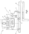
- the one Top view of a first embodiment of a Assembly station 87 shows the assembly of fittings with the help of the gripper device 5 and Screwdriver device 31 explained in more detail.
- the sash 45 is with the help of a not shown Guide device in the assembly station 87 introduced (arrow 89) such that the longitudinal axis of their respective fittings Holmes aligned parallel to the linear guide 43 is.
- magazines 91.1, 91.2, 91.3, 91.4 and 91.5 are magazines 91.1, 91.2, 91.3, 91.4 and 91.5 arranged, in which different versions of corner fittings, for example corner drives.
- magazines 93.1, 93.2 and 93.3 for different ones Embodiments of long parts to Example center locks, arranged.
- the magazines are preferably located below the mounting position of the casement.
- the gripper device 5 can give the magazines a desired one Fitting part can be removed.
- the gripper device 5 around a parallel to the linear guide 43 extending axis, for example 90 ° downwards pivotable and if necessary with suitable Medium vertically shiftable to one of the magazines a fitting part provided therein in the of the previous figures described manner refer to.
- the gripper device 5 is another Upstream gripper device 95, in particular for attaching a corner hinge Serve corner fitting, of which in a magazine 97 several embodiments of the corner hinge for different sash frames are provided.
- the casement 45 swiveled by 90 ° and here against it Transport direction transported back by a certain path length, so that on the longitudinal spar 102 in fitting parts can be attached accordingly.
- the sash 45 is again 90 ° pivoted so that 101 fittings on the lower cross member can be assembled.
- fittings preferably together chained.
- the sash 45 from the assembly station 87 transported out and for example one second assembly station, in which the second Longitudinal beam 104, i.e. the hinge side of the casement, is provided with fittings.
- the assembly station 87 there are therefore several corner fittings and long parts one after the other in a certain Order attached to the casement, a chaining of the parts together allows during their assembly.
- FIG. 4 shows a further embodiment of the Assembly station 87. Parts that match those of the previous ones Figures match, are the same Provide reference numerals so that the description of which is referenced. Hereinafter should only go into the differences in more detail become. So that the sash 45 in the assembly station 87 does not have to be rotated every time on the cross bars 99, 101 and the longitudinal bars 102 and 104 fittings using the along the linear guide Being able to attach 43 is a second Mounting device 1 'provided, its structure and Function corresponds to the mounting device 1. The linear guide 43 of the mounting device 1 'runs perpendicular to the guideway of the casement and thus also to the linear guide 43 of the Mounting device 1, which in turn is parallel to Guideway of the casement is arranged.
- the Mounting device 1 ' are magazines 106.1 and 106.2 for corner fittings and here just a magazine 107.1 assigned to an embodiment of the long part.
- the mounting device 1 With the help of the mounting device 1 only the longitudinal spar 104 (hinge side) and with the mounting device 1 ', which in the guideway of the sash 45th is retractable, first the upper cross member 99 with appropriate fittings. This can done simultaneously. Then the jig 1 'from the guideway of the casement for example, the one shown in dashed lines in FIG Position extended so that the casement 45 the assembly device 1 'in the event of a shift towards his guideway at which 4 from left to right, can happen.
- FIG. 9 shows a further embodiment of the Mounting device 1, which is different from that based on the Figures 1, 3 and 4 described assembly device 1 distinguishes in particular in that the gripper device 5 opposite the transport device 39 is displaceable on this (double arrow 110).
- This is one in this embodiment pneumatic or hydraulic piston and cylinder unit indicated second lifting device 111 provided, for example, fixed on the Transport device 39 is attached and at a Extending or retracting movement of your piston rod 113 shifts the gripper device 5.
- Means the second lifting device 111 is preferred one with a first leg in the circumferential groove of the Sash frame arranged corner fitting in the direction of displacement of the transport device 39 so that the other leg in the designated Circumferential groove section is pressed in and screwed can be. Impressing the second Schenkels would also be relocated Transport device by an appropriate path control possible, which is very expensive is.
- the particular advantage of preferably pneumatic Piston and cylinder unit is that this can be controlled by force, which is easier to achieve is.
- closure elements With security windows it is necessary to use the closure elements if possible to be placed near the corner storage corner, as in this Wing corner no corner deflection with the on the Corner element usually located closure elements is provided. This will be another short center lock as no further coupling Element with mushroom closure element provided. This means that with this fitting system at least four center locks each window and French door size in the standard and security area machine-loaded. It is advantageous that the long parts are relatively short and only four magazine locations prove what the assembly speed increased and the machine costs reduced.
- the center locks for the hinge side and for the lower cross member of the casement are in such Lengths provided that all common sash sizes preferably at the same time Coupling of the parts can be assembled and at the same time the most frequently produced Sash frame sizes only require one part each is, so the assembly speed can be increased significantly since there are no more Coupling elements are required.
- a preferred one The length of the center locks is 200 mm, 400 mm and 600 mm.
- corner drives fixed corner components such as Falzaxerstulp or corner band locks as well as long parts, such as center locks, each in the same way on one Shape, i.e. gripping or functional slot, on the faceplate of the gripper device recorded and in the circumferential groove of the casement used and with at least one Fixed screw connection.
- corner assemblies preferably on the leg perpendicular to Cuff rail gripped on which the closure element located.
- the gripper holder on the long parts also takes place perpendicular to the faceplate of the long part.
- the minimum configuration of the shape at the Hardware components is the functional slot for the Closure element. With long parts there is also at least the functional slot for the Stroke of the closure element on the component. Because the long parts have a larger faceplate length than the corner fittings, there are further gripper slots in the faceplate.
- Corner drives and corner assemblies are preferred of which by the second and third gripping elements 15, 19 formed gripping element pair added, while the first gripping element 13 outside or is arranged next to the corner assembly. In the case of long parts, only the two outer ones work Gripping elements 13, 19, while the second gripping element 15 in an appropriately positioned franking engages in the faceplate.
- the gripper position in the middle of the Faceplate is at short Long part the gripper position in the middle of the Faceplate. It can be for a gripping element Functional slot of the closure can be used, so that only two more gripping slots in the rail must be introduced. With long parts with If the length is greater, the gripping position is preferably off-center located near the coupling point, so that the joining forces for the coupling process of the gripper device can be picked up. There the functional slot of the closure element itself the coupling point of the opposite long part end located, it is required a total of three Insert gripping slots in the long part, whereby two outer slots for receiving the active Gripping elements and the inner slot as franking are needed for the second gripping element.
- the sash After inserting the parts into the circumferential groove of the The sash is the fitting part with the help of Screwdriver 33, 35 with at least one screw on Fixed sash frame.
- the arrangement of the through openings to the imaginary center line of the gripping position is symmetrical, that is, they have it same distance from the outer gripping element. With long parts there is symmetry of the screw position both to the center of the gripper and to Axis of rotation of the gripper head.
- the symmetrical positioning the through openings for screws to the axis of rotation of the gripper head 7 is in the case of functional slots, Corner drives and gripping slots Long parts given uniformly.
- the axis of rotation of the gripper device 5 is preferably with all versions - with included Corner deflections exactly on the top edge of the free-standing leg of the corner drive, see above that when you turn the corner assembly right or left to the axis of rotation and symmetry Screwdriver for fixing the assembly in the casement can be used.
- the axis of rotation of the Gripper device 5 is preferably included all versions - long parts exactly in the Middle between the two outer gripping elements 13 and 19, so that here too when loading right and left casement each the same Fitting part can be gripped from the magazine and by rotating through 180 ° about the axis of rotation 9 of the Gripper head 7, the coupling element respectively the coupling section of the fitting part into the correct one Position can be brought.
Landscapes
- Engineering & Computer Science (AREA)
- Mechanical Engineering (AREA)
- Manufacturing & Machinery (AREA)
- Door And Window Frames Mounted To Openings (AREA)
- Automatic Assembly (AREA)
- Automobile Manufacture Line, Endless Track Vehicle, Trailer (AREA)
- Hinges (AREA)
- Wing Frames And Configurations (AREA)
Abstract
Description
- Figur 1
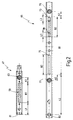
- eine Prinzipskizze eines ersten Ausführungsbeispiels einer Montagevorrichtung zur maschinellen Montage von Beschlagteilen an einem Flügelrahmen eines Fensters und jeweils eine Seitenansicht und eine Draufsicht auf unterschiedliche Beschlagteile;
- Figur 2
- jeweils eine Draufsicht auf die Flachseite eines Eckbeschlags und eines Langteils;
- Figur 3
- einen Ausschnitt aus einem Ausführungsbeispiel einer Montagestation für Beschlagteile in Draufsicht;
- Figur 4
- einen Ausschnitt aus einem zweiten Ausführungsbeispiel der Montagestation in Draufsicht;
- Figur 5
- jeweils eine Seitenansicht und eine Draufsicht auf mehrere Langteile unterschiedlicher Länge;
- Figuren 6 bis 8
- jeweils eine Draufsicht und eine Seitenansicht verschiedener Ausführungsbeispiele eines Eckbeschlags und
- Figur 9
- eine Prinzipskizze eines weiteren Ausführungsbeispiels der Montagevorrichtung.
Claims (20)
- Vorrichtung zur maschinellen Montage von Beschlagteilen an Flügel- und/oder Blendrahmen von Fenstern, Türen oder dergleichen, mit einer Zuführeinrichtung (3) und einer Befestigungseinrichtung, wobei die Zuführeinrichtung (3) mindestens ein mit dem zu montierenden Beschlagteil zusammenwirkendes Funktionselement umfaßt, dadurch gekennzeichnet, daß die Zuführeinrichtung (3) derart ausgebildet ist, daß sowohl Eckbeschläge als auch Langteile montierbar sind.
- Montagevorrichtung nach Anspruch 1, dadurch gekennzeichnet, daß die Zuführeinrichtung (3) als Greifereinrichtung (5) ausgebildet ist, die mindestens einen Greiferkopf (7) mit mehreren Greifelementen (13,15,19) umfaßt, von denen ein erstes Greifelement (13) und ein zweites Greifelement (15) in einem fixen Abstand (X1) voneinander angeordnet sind und daß ein drittes Greifelement (19) gegenüber den ersten und zweiten Greifelementen (13;15) verlagerbar ausgebildet ist.
- Montagevorrichtung nach einem der vorhergehenden Ansprüche, dadurch gekennzeichnet, daß das zweite Greifelement (15) zwischen den ersten und dritten Greifelementen (13;19) angeordnet ist.
- Montagevorrichtung nach einem der vorhergehenden Ansprüche, dadurch gekennzeichnet, daß mittels der ersten und dritten Greifelemente (13;19) ein Eckbeschlag und mit Hilfe der zweiten und dritten Greifelemente (15;19) ein Langteil klemmend haltbar ist.
- Montagevorrichtung nach einem der vorhergehenden Ansprüche, dadurch gekennzeichnet, daß mindestens ein Greifelement (13,15,19) als Greiffinger ausgebildet ist, der in einen Greifschlitz oder einen Funktionsschlitz im Beschlagteil eingreifbar ausgebildet ist.
- Montagevorrichtung nach einem der vorhergehenden Ansprüche, dadurch gekennzeichnet, daß die Greifereinrichtung (5) und die Befestigungseinrichtung (29) an einer entlang der Längsachse mindestens eines Holmes (99,101,102,104) des Flügel- und/oder Blendrahmens (45) frei verfahrbar geführten Transporteinrichtung (39) angeordnet sind.
- Montagevorrichtung nach einem der vorhergehenden Ansprüche, dadurch gekennzeichnet, daß die Greifereinrichtung (5) und die Befestigungseinrichtung (29) quer oder im wesentlichen quer zur Längsachse des Holmes (99,101,102,104) frei verfahrbar sind.
- Montagevorrichtung nach einem der vorhergehenden Ansprüche, dadurch gekennzeichnet, daß der Greiferkopf (7) um eine in dem Bereich zwischen den ersten und zweiten Greifelementen (13,15) angeordnete Drehachse (9) schwenkbar und/oder rotierbar ausgebildet ist.
- Montagevorrichtung nach einem der vorhergehenden Ansprüche, dadurch gekennzeichnet, daß die ersten und zweiten Greifelemente (13,15) einen unterschiedlichen Abstand zur Drehachse (9) des Greiferkopfs (7) aufweisen.
- Montagevorrichtung nach einem der vorhergehenden Ansprüche, dadurch gekennzeichnet, daß die Befestigungseinrichtung (29) von einer mindestens einen Schrauber (33;35) umfassende Schraubereinrichtung (31) gebildet ist, wobei der Schrauber (33;35) derart angeordnet ist, daß auch bei einer Verlagerung der Greifereinrichtung (5) der Abstand (X5;X4) zwischen dem Schrauber (35;33) und der Drehachse (9) des Greiferkopfs (7) konstant ist.
- Montagevorrichtung nach einem der vorhergehenden Ansprüche, dadurch gekennzeichnet, daß die Schraubereinrichtung (31) zwei in einem fixen Abstand voneinander angeordnete Schrauber (33,35) umfaßt, deren jeweiliger Abstand (X4;X5) zu der zwischen den ersten und zweiten Schraubern (33,35) angeordneten Drehachse (9) des Greiferkopfs (7) gleich ist.
- Montagevorrichtung nach einem der vorhergehenden Ansprüche, dadurch gekennzeichnet, daß der Abstand (X6') zwischen dem zweiten Schrauber (35;33) und dem in einer Klemmstellung angeordneten dritten Greifelement (19) gleich groß ist, wie der Abstand (X6) zwischen dem ersten Schrauber (33;35) und dem ersten Greifelement (13).
- Montagevorrichtung nach einem der vorhergehenden Ansprüche, dadurch gekennzeichnet, daß das dritte Greifelement (19) mit Hilfe einer -vorzugsweise pneumatischen oder hydraulischen- ersten Hubeinrichtung (21) gegenüber den ersten und zweiten Greifelementen (13,15) verlagerbar, vorzugsweise verschiebbar, ist.
- Montagevorrichtung nach einem der vorhergehenden Ansprüche, dadurch gekennzeichnet, daß die Greifereinrichtung (5) mit Hilfe einer -vorzugsweise pneumatischen oder hydraulischen- zweiten Hubeinrichtung (111) relativ gegenüber der Transporteinrichtung (39) in Richtung der Längsachse des Holmes (99,101,102,104) verlagerbar, vorzugsweise verschiebbar, ist.
- Montagevorrichtung nach einem der vorhergehenden Ansprüche, dadurch gekennzeichnet, daß die Greifereinrichtung (5) und gegebenenfalls die Befestigungseinrichtung (29) um eine parallel zur Längsachse des Holmes (99,101) verlaufende Querachse (108) schwenkbar und/oder rotierbar ausgebildet ist.
- Montagevorrichtung nach einem der vorhergehenden Ansprüche, dadurch gekennzeichnet, daß der freie Schenkel (61) eines durch die Zuführeinrichtung (3) aufgenommenen Eckbeschlags (47) mit der Drehachse (9) des Greiferkopfs (7) zumindest im wesentlichen fluchtet.
- Verfahren zur maschinellen Montage von Beschlagteilen an Flügel- und/oder Blendrahmen von Fenstern, Türen oder dergleichen, insbesondere mit Hilfe einer Vorrichtung nach einem oder mehreren der vorhergehenden Ansprüche 1 bis 15, bei dem in einem ersten Bearbeitungsschritt mindestens einem Holm des sich an einem Montageort befindlichen Flügel- und/oder Blendrahmens mindestens ein maschinell gegriffenes Beschlagteil zugeführt wird, das in einem zweiten Bearbeitungsschritt maschinell an dem Holm festgeschraubt wird, dadurch gekennzeichnet, daß an dem Montageort mindestens ein Eckbeschlag und mindestens ein Langteil an dem Holm montiert wird.
- Verfahren nach Anspruch 17, dadurch gekennzeichnet, daß mehrere gleiche oder unterschiedliche Beschlagteile gleichzeitig an dem Holm montiert werden.
- Verfahren nach einem der vorhergehenden Ansprüche, dadurch gekennzeichnet, daß das Beschlagteil nach der Zuführung an den Holm durch Einklipsen oder Einpressen in eine Flügel-/Blendrahmenfalz-Umfangsnut vorfixiert wird.
- Verfahren nach einem der vorhergehenden Ansprüche, dadurch gekennzeichnet, daß die Montagerichtung der Beschlagteile senkrecht zur Flügel-/Blendrahmenfalz-Umfangsnut verläuft.
Applications Claiming Priority (2)
| Application Number | Priority Date | Filing Date | Title |
|---|---|---|---|
| DE19952492 | 1999-10-30 | ||
| DE19952492A DE19952492B4 (de) | 1999-10-30 | 1999-10-30 | Vorrichtung und Verfahren zur maschinellen Montage von Beschlagteilen an Flügel- und/oder Blendrahmen von Fenstern, Türen oder dergleichen |
Publications (2)
| Publication Number | Publication Date |
|---|---|
| EP1095729A1 true EP1095729A1 (de) | 2001-05-02 |
| EP1095729B1 EP1095729B1 (de) | 2005-01-19 |
Family
ID=7927530
Family Applications (1)
| Application Number | Title | Priority Date | Filing Date |
|---|---|---|---|
| EP00120518A Expired - Lifetime EP1095729B1 (de) | 1999-10-30 | 2000-09-20 | Vorrichtung und Verfahren zur maschinellen Montage von Beschlagteilen an Flügel und/oder Blendrahmen von Fenstern, Türen oder dergleichen |
Country Status (3)
| Country | Link |
|---|---|
| EP (1) | EP1095729B1 (de) |
| AT (1) | ATE287316T1 (de) |
| DE (2) | DE19952492B4 (de) |
Cited By (7)
| Publication number | Priority date | Publication date | Assignee | Title |
|---|---|---|---|---|
| EP1260661A3 (de) * | 2001-05-26 | 2004-04-14 | Roto Frank Ag | Treibstangen-Montagesatz, entsprechendes Dreh-Kipp-Fenster oder -Tür und Verfahren zur Montage eines derartigen Montagesatzes |
| EP2366479A1 (de) * | 2010-03-16 | 2011-09-21 | Emmegi S.P.A. | Anlage und Verfahren zur Herstellung von Rahmen für Fenster oder Türen |
| CN109676376A (zh) * | 2019-02-28 | 2019-04-26 | 北京理工大学珠海学院 | 活动杆与活动球装配装置及其使用方法 |
| CN113878340A (zh) * | 2021-09-26 | 2022-01-04 | 湖南亘晟门窗幕墙有限公司 | 门框连杆自动装配线 |
| CN115055941A (zh) * | 2022-06-09 | 2022-09-16 | 浙江百家万安门业有限公司 | 一种门体便捷化高效组装系统 |
| CN117140027A (zh) * | 2023-10-16 | 2023-12-01 | 山东雷德数控机械股份有限公司 | 一种门窗组角生产线及工作方法 |
| CN117533720A (zh) * | 2023-12-13 | 2024-02-09 | 济南天辰智能装备股份有限公司 | 一种门窗生产线及生产方法 |
Families Citing this family (1)
| Publication number | Priority date | Publication date | Assignee | Title |
|---|---|---|---|---|
| DE10211990A1 (de) * | 2002-03-18 | 2003-10-02 | Afs Holding Gmbh | Vorrichtung zum automatischen Anbringen von Beschlägen an Fenstern, Türen und dergleichen |
Citations (5)
| Publication number | Priority date | Publication date | Assignee | Title |
|---|---|---|---|---|
| EP0683297A1 (de) * | 1994-05-20 | 1995-11-22 | August Winkhaus GmbH & Co KG | Verfahren zur montageautomaten-unterstützten Montage von Beschlagsteilen an den Flügel eines Fensters, einer Tür oder dergleichen |
| DE4445888A1 (de) * | 1994-12-22 | 1996-06-27 | Federhenn Maschinen Gmbh | Vorrichtung für die Montage von Fensterflügeln und anderen Gegenständen |
| DE19712082A1 (de) * | 1997-03-22 | 1998-09-24 | Lemuth Praezisionsteile Gmbh | Verfahren und Einrichtung zur automatischen Montage von Beschlagteilen an den Flügeln eines Fensters oder dergleichen |
| EP0886026A2 (de) * | 1997-06-17 | 1998-12-23 | Aug. Winkhaus GmbH & Co. KG | Drehkipp-Beschlag-System |
| EP0988922A2 (de) * | 1998-09-21 | 2000-03-29 | ROTO FRANK Aktiengesellschaft | Verfahren zur maschinellen Montage von Beschlagteilen an Flügel- und/oder Blendrahmen von Fenstern, Türen oder dergleichen und Vorrichtung zur maschinellen Montage von Beschlagteilen an Flügel- und/oder Blendrahmen von Fenstern, Türen oder dergleichen |
Family Cites Families (1)
| Publication number | Priority date | Publication date | Assignee | Title |
|---|---|---|---|---|
| DE4033602A1 (de) * | 1990-10-23 | 1992-04-30 | Kumeth Siegmund | Wendegreifer zur verwendung bei montagemaschinen oder -automaten sowie greiferkopf fuer einen solchen wendegreifer |
-
1999
- 1999-10-30 DE DE19952492A patent/DE19952492B4/de not_active Expired - Fee Related
-
2000
- 2000-09-20 EP EP00120518A patent/EP1095729B1/de not_active Expired - Lifetime
- 2000-09-20 AT AT00120518T patent/ATE287316T1/de active
- 2000-09-20 DE DE50009270T patent/DE50009270D1/de not_active Expired - Lifetime
Patent Citations (5)
| Publication number | Priority date | Publication date | Assignee | Title |
|---|---|---|---|---|
| EP0683297A1 (de) * | 1994-05-20 | 1995-11-22 | August Winkhaus GmbH & Co KG | Verfahren zur montageautomaten-unterstützten Montage von Beschlagsteilen an den Flügel eines Fensters, einer Tür oder dergleichen |
| DE4445888A1 (de) * | 1994-12-22 | 1996-06-27 | Federhenn Maschinen Gmbh | Vorrichtung für die Montage von Fensterflügeln und anderen Gegenständen |
| DE19712082A1 (de) * | 1997-03-22 | 1998-09-24 | Lemuth Praezisionsteile Gmbh | Verfahren und Einrichtung zur automatischen Montage von Beschlagteilen an den Flügeln eines Fensters oder dergleichen |
| EP0886026A2 (de) * | 1997-06-17 | 1998-12-23 | Aug. Winkhaus GmbH & Co. KG | Drehkipp-Beschlag-System |
| EP0988922A2 (de) * | 1998-09-21 | 2000-03-29 | ROTO FRANK Aktiengesellschaft | Verfahren zur maschinellen Montage von Beschlagteilen an Flügel- und/oder Blendrahmen von Fenstern, Türen oder dergleichen und Vorrichtung zur maschinellen Montage von Beschlagteilen an Flügel- und/oder Blendrahmen von Fenstern, Türen oder dergleichen |
Cited By (10)
| Publication number | Priority date | Publication date | Assignee | Title |
|---|---|---|---|---|
| EP1260661A3 (de) * | 2001-05-26 | 2004-04-14 | Roto Frank Ag | Treibstangen-Montagesatz, entsprechendes Dreh-Kipp-Fenster oder -Tür und Verfahren zur Montage eines derartigen Montagesatzes |
| EP2366479A1 (de) * | 2010-03-16 | 2011-09-21 | Emmegi S.P.A. | Anlage und Verfahren zur Herstellung von Rahmen für Fenster oder Türen |
| CN109676376A (zh) * | 2019-02-28 | 2019-04-26 | 北京理工大学珠海学院 | 活动杆与活动球装配装置及其使用方法 |
| CN109676376B (zh) * | 2019-02-28 | 2024-02-20 | 北京理工大学珠海学院 | 活动杆与活动球装配装置及其使用方法 |
| CN113878340A (zh) * | 2021-09-26 | 2022-01-04 | 湖南亘晟门窗幕墙有限公司 | 门框连杆自动装配线 |
| CN115055941A (zh) * | 2022-06-09 | 2022-09-16 | 浙江百家万安门业有限公司 | 一种门体便捷化高效组装系统 |
| CN115055941B (zh) * | 2022-06-09 | 2023-09-01 | 浙江百家万安门业有限公司 | 一种门体便捷化高效组装系统 |
| CN117140027A (zh) * | 2023-10-16 | 2023-12-01 | 山东雷德数控机械股份有限公司 | 一种门窗组角生产线及工作方法 |
| CN117140027B (zh) * | 2023-10-16 | 2024-04-12 | 山东雷德数控机械股份有限公司 | 一种门窗组角生产线及工作方法 |
| CN117533720A (zh) * | 2023-12-13 | 2024-02-09 | 济南天辰智能装备股份有限公司 | 一种门窗生产线及生产方法 |
Also Published As
| Publication number | Publication date |
|---|---|
| DE19952492B4 (de) | 2004-11-04 |
| EP1095729B1 (de) | 2005-01-19 |
| DE19952492A1 (de) | 2001-05-17 |
| DE50009270D1 (de) | 2005-02-24 |
| ATE287316T1 (de) | 2005-02-15 |
Similar Documents
| Publication | Publication Date | Title |
|---|---|---|
| EP0683297B1 (de) | Verfahren zur montageautomaten-unterstützten Montage von Beschlagsteilen an den Flügel eines Fensters, einer Tür oder dergleichen | |
| EP3271538A1 (de) | Tür- oder fensterscharnier | |
| DE102020102207B4 (de) | Vorrichtung zum Bewegen einer Schiebetür oder Falt-Schiebetür | |
| EP0711896A2 (de) | Verschlussvorrichtung für Fenster, Türen od. dgl. | |
| DE19952492B4 (de) | Vorrichtung und Verfahren zur maschinellen Montage von Beschlagteilen an Flügel- und/oder Blendrahmen von Fenstern, Türen oder dergleichen | |
| DE69408612T2 (de) | Antriebs- und Arretiervorrichtung für Kraftfahrzeugfenster | |
| DE602006000992T2 (de) | Maschine zur Herstellung von Türrahmen | |
| EP0886026B1 (de) | Drehkipp-Beschlag-System | |
| EP4015749A1 (de) | Befestigungseinrichtung zur befestigung eines beschlagteils an einem eine nut aufweisenden rahmen einer gebäudeverschlusseinrichtung, gebäudeverschlusseinrichtung sowie verfahren zum befestigen eines beschlagteils an einem rahmen einer gebäudeverschlusseinrichtung | |
| EP0988922B1 (de) | Verfahren zur maschinellen Montage von Beschlagteilen an Flügel- und/oder Blendrahmen von Fenstern, Türen oder dergleichen und Vorrichtung zur maschinellen Montage von Beschlagteilen an Flügel- und/oder Blendrahmen von Fenstern, Türen oder dergleichen | |
| EP0616108B1 (de) | Lamellenstore | |
| EP4146888B1 (de) | Scharnierbaugruppe mit gemeinsamer betätigung | |
| DE19712082C2 (de) | Vorrichtung zur automatischen Montage von Beschlagteilen an den Flügeln eines Fensters oder dergleichen | |
| EP1321606B1 (de) | Profilzylinder | |
| EP0574825A1 (de) | Verfahren und Vorrichtung für das Befestigen der Bandteile an Fensterrahmen und -flügeln | |
| EP1041223B1 (de) | Automatische Beschlagteilmontage für Rahmen | |
| EP0896120B1 (de) | Verfahren und Scharnierbeschlag für eine montageautomatenunterstützte Montage an einem Flügel eines Fenster, einer Tür oder dergleichen | |
| DE19526016A1 (de) | Exzenterverstelleinrichtung für einen Beschlag für Fenster, Türen oder dergleichen | |
| EP3029242B1 (de) | System zur Anordnung eines Türelements an einer Türanlage | |
| DE102020112148B3 (de) | Scharnierverschluss | |
| DE29600891U1 (de) | Sicherungseinrichtung | |
| WO2007073989A1 (de) | Gleitstück für einen beschlag | |
| EP3656955B1 (de) | Schliessteil | |
| WO2003087508A1 (de) | Kopplungsvorrichtung | |
| DE3041511A1 (de) | Dreh-kipp-beschlag fuer fenster, tueren o.dgl. |
Legal Events
| Date | Code | Title | Description |
|---|---|---|---|
| PUAI | Public reference made under article 153(3) epc to a published international application that has entered the european phase |
Free format text: ORIGINAL CODE: 0009012 |
|
| AK | Designated contracting states |
Kind code of ref document: A1 Designated state(s): AT CH DE FR IT LI |
|
| AX | Request for extension of the european patent |
Free format text: AL;LT;LV;MK;RO;SI |
|
| 17P | Request for examination filed |
Effective date: 20010926 |
|
| AKX | Designation fees paid |
Free format text: AT CH DE FR IT LI |
|
| 17Q | First examination report despatched |
Effective date: 20040109 |
|
| GRAP | Despatch of communication of intention to grant a patent |
Free format text: ORIGINAL CODE: EPIDOSNIGR1 |
|
| GRAS | Grant fee paid |
Free format text: ORIGINAL CODE: EPIDOSNIGR3 |
|
| GRAA | (expected) grant |
Free format text: ORIGINAL CODE: 0009210 |
|
| AK | Designated contracting states |
Kind code of ref document: B1 Designated state(s): AT CH DE FR IT LI |
|
| REG | Reference to a national code |
Ref country code: CH Ref legal event code: EP |
|
| REF | Corresponds to: |
Ref document number: 50009270 Country of ref document: DE Date of ref document: 20050224 Kind code of ref document: P |
|
| REG | Reference to a national code |
Ref country code: CH Ref legal event code: NV Representative=s name: E. BLUM & CO. PATENTANWAELTE |
|
| PLBE | No opposition filed within time limit |
Free format text: ORIGINAL CODE: 0009261 |
|
| STAA | Information on the status of an ep patent application or granted ep patent |
Free format text: STATUS: NO OPPOSITION FILED WITHIN TIME LIMIT |
|
| ET | Fr: translation filed | ||
| 26N | No opposition filed |
Effective date: 20051020 |
|
| REG | Reference to a national code |
Ref country code: CH Ref legal event code: PFA Owner name: ROTO FRANK AG Free format text: ROTO FRANK AG#STUTTGARTER STRASSE 145-149#70771 LEINFELDEN-ECHTERDINGEN (DE) -TRANSFER TO- ROTO FRANK AG#STUTTGARTER STRASSE 145-149#70771 LEINFELDEN-ECHTERDINGEN (DE) |
|
| REG | Reference to a national code |
Ref country code: DE Ref legal event code: R084 Ref document number: 50009270 Country of ref document: DE |
|
| REG | Reference to a national code |
Ref country code: DE Ref legal event code: R081 Ref document number: 50009270 Country of ref document: DE Owner name: ROTO FRANK AKTIENGESELLSCHAFT, DE Free format text: FORMER OWNER: ROTO FRANK AG, 70771 LEINFELDEN-ECHTERDINGEN, DE |
|
| REG | Reference to a national code |
Ref country code: FR Ref legal event code: PLFP Year of fee payment: 17 |
|
| REG | Reference to a national code |
Ref country code: FR Ref legal event code: PLFP Year of fee payment: 18 |
|
| PGFP | Annual fee paid to national office [announced via postgrant information from national office to epo] |
Ref country code: AT Payment date: 20170920 Year of fee payment: 18 |
|
| REG | Reference to a national code |
Ref country code: FR Ref legal event code: PLFP Year of fee payment: 19 |
|
| PGFP | Annual fee paid to national office [announced via postgrant information from national office to epo] |
Ref country code: FR Payment date: 20180921 Year of fee payment: 19 Ref country code: IT Payment date: 20180921 Year of fee payment: 19 Ref country code: DE Payment date: 20180924 Year of fee payment: 19 |
|
| PGFP | Annual fee paid to national office [announced via postgrant information from national office to epo] |
Ref country code: CH Payment date: 20180924 Year of fee payment: 19 |
|
| REG | Reference to a national code |
Ref country code: AT Ref legal event code: MM01 Ref document number: 287316 Country of ref document: AT Kind code of ref document: T Effective date: 20180920 |
|
| PG25 | Lapsed in a contracting state [announced via postgrant information from national office to epo] |
Ref country code: AT Free format text: LAPSE BECAUSE OF NON-PAYMENT OF DUE FEES Effective date: 20180920 |
|
| REG | Reference to a national code |
Ref country code: DE Ref legal event code: R119 Ref document number: 50009270 Country of ref document: DE |
|
| REG | Reference to a national code |
Ref country code: CH Ref legal event code: PL |
|
| PG25 | Lapsed in a contracting state [announced via postgrant information from national office to epo] |
Ref country code: DE Free format text: LAPSE BECAUSE OF NON-PAYMENT OF DUE FEES Effective date: 20200401 Ref country code: CH Free format text: LAPSE BECAUSE OF NON-PAYMENT OF DUE FEES Effective date: 20190930 Ref country code: LI Free format text: LAPSE BECAUSE OF NON-PAYMENT OF DUE FEES Effective date: 20190930 |
|
| PG25 | Lapsed in a contracting state [announced via postgrant information from national office to epo] |
Ref country code: IT Free format text: LAPSE BECAUSE OF NON-PAYMENT OF DUE FEES Effective date: 20190920 |
|
| PG25 | Lapsed in a contracting state [announced via postgrant information from national office to epo] |
Ref country code: FR Free format text: LAPSE BECAUSE OF NON-PAYMENT OF DUE FEES Effective date: 20190930 |