EP1095588B1 - Merhzweck Vorrichtung mit hin un Zurückbeweglichem Stift - Google Patents
Merhzweck Vorrichtung mit hin un Zurückbeweglichem Stift Download PDFInfo
- Publication number
- EP1095588B1 EP1095588B1 EP00309353A EP00309353A EP1095588B1 EP 1095588 B1 EP1095588 B1 EP 1095588B1 EP 00309353 A EP00309353 A EP 00309353A EP 00309353 A EP00309353 A EP 00309353A EP 1095588 B1 EP1095588 B1 EP 1095588B1
- Authority
- EP
- European Patent Office
- Prior art keywords
- barrel
- rod
- cap
- casing
- hand
- Prior art date
- Legal status (The legal status is an assumption and is not a legal conclusion. Google has not performed a legal analysis and makes no representation as to the accuracy of the status listed.)
- Expired - Lifetime
Links
Images


Classifications
-
- B—PERFORMING OPERATIONS; TRANSPORTING
- B43—WRITING OR DRAWING IMPLEMENTS; BUREAU ACCESSORIES
- B43K—IMPLEMENTS FOR WRITING OR DRAWING
- B43K24/00—Mechanisms for selecting, projecting, retracting or locking writing units
- B43K24/02—Mechanisms for selecting, projecting, retracting or locking writing units for locking a single writing unit in only fully projected or retracted positions
- B43K24/06—Mechanisms for selecting, projecting, retracting or locking writing units for locking a single writing unit in only fully projected or retracted positions operated by turning means
-
- A—HUMAN NECESSITIES
- A45—HAND OR TRAVELLING ARTICLES
- A45D—HAIRDRESSING OR SHAVING EQUIPMENT; EQUIPMENT FOR COSMETICS OR COSMETIC TREATMENTS, e.g. FOR MANICURING OR PEDICURING
- A45D40/00—Casings or accessories specially adapted for storing or handling solid or pasty toiletry or cosmetic substances, e.g. shaving soaps or lipsticks
- A45D40/02—Casings wherein movement of the lipstick or like solid is a sliding movement
-
- A—HUMAN NECESSITIES
- A45—HAND OR TRAVELLING ARTICLES
- A45D—HAIRDRESSING OR SHAVING EQUIPMENT; EQUIPMENT FOR COSMETICS OR COSMETIC TREATMENTS, e.g. FOR MANICURING OR PEDICURING
- A45D40/00—Casings or accessories specially adapted for storing or handling solid or pasty toiletry or cosmetic substances, e.g. shaving soaps or lipsticks
- A45D40/26—Appliances specially adapted for applying pasty paint, e.g. using roller, using a ball
- A45D40/28—Appliances specially adapted for spreading already applied paint
-
- A—HUMAN NECESSITIES
- A46—BRUSHWARE
- A46B—BRUSHES
- A46B7/00—Bristle carriers arranged in the brush body
- A46B7/02—Bristle carriers arranged in the brush body in an expanding or articulating manner
- A46B7/023—Bristle carriers arranged in the brush body in an expanding or articulating manner where the bristle carrier retracts or collapses, i.e. for storage
-
- B—PERFORMING OPERATIONS; TRANSPORTING
- B43—WRITING OR DRAWING IMPLEMENTS; BUREAU ACCESSORIES
- B43K—IMPLEMENTS FOR WRITING OR DRAWING
- B43K5/00—Pens with ink reservoirs in holders, e.g. fountain-pens
- B43K5/16—Pens with ink reservoirs in holders, e.g. fountain-pens with retractable nibs
- B43K5/17—Pens with ink reservoirs in holders, e.g. fountain-pens with retractable nibs with closing means
-
- B—PERFORMING OPERATIONS; TRANSPORTING
- B43—WRITING OR DRAWING IMPLEMENTS; BUREAU ACCESSORIES
- B43K—IMPLEMENTS FOR WRITING OR DRAWING
- B43K7/00—Ball-point pens
- B43K7/005—Pen barrels
-
- B—PERFORMING OPERATIONS; TRANSPORTING
- B43—WRITING OR DRAWING IMPLEMENTS; BUREAU ACCESSORIES
- B43K—IMPLEMENTS FOR WRITING OR DRAWING
- B43K8/00—Pens with writing-points other than nibs or balls
- B43K8/003—Pen barrels
-
- A—HUMAN NECESSITIES
- A45—HAND OR TRAVELLING ARTICLES
- A45D—HAIRDRESSING OR SHAVING EQUIPMENT; EQUIPMENT FOR COSMETICS OR COSMETIC TREATMENTS, e.g. FOR MANICURING OR PEDICURING
- A45D40/00—Casings or accessories specially adapted for storing or handling solid or pasty toiletry or cosmetic substances, e.g. shaving soaps or lipsticks
- A45D2040/0025—Details of lipstick or like casings
- A45D2040/0031—Replacement of the stick
- A45D2040/005—Replacement of the stick by removing the old stick from the cartridge by linear, sliding movement of stick relative to the cartridge
-
- A—HUMAN NECESSITIES
- A45—HAND OR TRAVELLING ARTICLES
- A45D—HAIRDRESSING OR SHAVING EQUIPMENT; EQUIPMENT FOR COSMETICS OR COSMETIC TREATMENTS, e.g. FOR MANICURING OR PEDICURING
- A45D40/00—Casings or accessories specially adapted for storing or handling solid or pasty toiletry or cosmetic substances, e.g. shaving soaps or lipsticks
- A45D40/20—Pencil-like cosmetics; Simple holders for handling stick-shaped cosmetics or shaving soap while in use
- A45D2040/204—Pencil-like cosmetics; Simple holders for handling stick-shaped cosmetics or shaving soap while in use the cosmetic being in a cartridge
-
- A—HUMAN NECESSITIES
- A45—HAND OR TRAVELLING ARTICLES
- A45D—HAIRDRESSING OR SHAVING EQUIPMENT; EQUIPMENT FOR COSMETICS OR COSMETIC TREATMENTS, e.g. FOR MANICURING OR PEDICURING
- A45D40/00—Casings or accessories specially adapted for storing or handling solid or pasty toiletry or cosmetic substances, e.g. shaving soaps or lipsticks
- A45D40/20—Pencil-like cosmetics; Simple holders for handling stick-shaped cosmetics or shaving soap while in use
- A45D40/205—Holders for stick-shaped cosmetics whereby the stick can move axially relative to the holder
- A45D2040/208—Holders for stick-shaped cosmetics whereby the stick can move axially relative to the holder the relative movement being made by a rotating action, e.g. effected by a screw
-
- A—HUMAN NECESSITIES
- A46—BRUSHWARE
- A46B—BRUSHES
- A46B2200/00—Brushes characterized by their functions, uses or applications
- A46B2200/10—For human or animal care
- A46B2200/1046—Brush used for applying cosmetics
Definitions
- the present invention relates to a hand-held multipurpose casing provided with a unit for reversibly extending a functional tipped device housed within the casing, for example, a ballpoint pen cartridge or a makeup brush, and, more particularly, to a hand-held multipurpose casing having a cylinder-type or screw-type actuating unit capable of reversibly extending such a functional tipped device, the casing also having an automatically operated protective cover for the functional tipped device.
- makeup brushes such as loose powder brushes, fan brushes, lip brushes, mascara brushes, eyeliner brushes, or brow brushes, have been used by women, and actors or other performers.
- Such a conventional makeup brush comprises a hand-held casing, including a threaded rod housed within the casing and reversibly extending a brush from the casing by an action of the threaded bar or the threaded rod relative to the casing.
- the caps have to be removed from the casings when it is desired to use the makeup brushes, and so it is inconvenient to users.
- the caps may be carelessly lost and force the users to pay money for the purchase of new makeup brushes.
- US 2,607,942 on which the preambles of claims 1 and 8 are based, discloses a spring-retracted lip brush wherein a removable cap which can slide axially on a tubular body is provided with a ram rod which passes into the body to push a brush carrier and thereby advance a brush carried by the carrier to project from a forward end of the body.
- a hand-held multipurpose casing comprising: a front barrel having a front opening; a rear barrel; and a functional tipped device holder having a functional tipped device at its front tip, said holder being housed within said casing so as to be axially movable within the casing in response to an axial movement of the rear barrel, thus extending or retracting the functional tipped device from or into the front opening of said front barrel, characterised in that the casing further comprises: a middle barrel fixedly fitted into a rear end portion of said front barrel at its front end portion, said rear barrel being movably fitted at its front end portion over a rear end portion of said middle barrel so as to be axially movable on the middle barrel; a cap fixedly mounted to a rear end of said rear barrel, with two holding slots formed on a front end portion of an external surface of said cap at diametrically opposite positions; and a screw-type actuating unit movably engaging with both the functional tipped device holder
- a hand-held multipurpose casing comprising a front barrel having a front opening; a rear barrel; a functional tipped device housed within said casing so as to be axially movable within the casing in response to an axial movement of the rear barrel, and an actuating unit used for axially moving the functional tipped device in response to the axial movement of the rear barrel, thus extending or retracting the functional tipped device from or into the front opening of said front barrel, characterised in that said actuating unit comprises: a middle barrel fixedly fitted into a rear end portion of said front barrel at its front end portion, said rear barrel being movably fitted at its front end portion over a rear end portion of said middle barrel so as to be axially movable on the middle barrel; a rotatable rod having both an internal spiral thread at its front end portion and an external spiral thread at its rear end portion, with the spiral directions of the internal and external spiral threads being opposite to each other; a thrust rod holding said functional
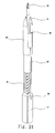
- Fig. 1 is a perspective view showing the profile of a hand-held multipurpose casing, having a screw-type actuating unit and used as a makeup brush casing, in accordance with the primary embodiment of the present invention.
- Fig. 2 is a perspective view, showing an operation of the hand-held multipurpose casing of Fig. 1.
- Fig. 3 is a sectional view of the hand-held multipurpose casing of Fig. 1.
- Fig. 4 is a sectional view, showing the operation of the hand-held multipurpose casing of Fig. 3.
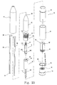
- Fig. 5 is an exploded perspective view of the hand-held multipurpose casing of Fig. 1.
- the hand-held multipurpose casing As shown in Figs. 1 and 2, the hand-held multipurpose casing according to the primary embodiment of the present invention comprises a hollow front barrel 13, having a cylindrical shape with a conical front end, a hollow middle barrel 12 having a cylindrical shape, and a hollow rear barrel 15. A cap 16 is fitted into the rear end of the cylindrical rear barrel 15.
- the multipurpose casing of this invention houses a screw-type actuating unit used for projecting or retracting a makeup brush 33 relative to the casing.
- the rear barrel 15 is movably fitted over the rear end portion of the middle barrel 12 so as to be axially slidable on the middle barrel 12 in opposite directions as desired.
- the screw-type actuating unit housed within the multipurpose casing according to the primary embodiment, comprises a rotatable rod 110, a packing plug 120, a thrust rod 31, two guide bars 115, and a brush holder 18.
- the rotatable rod 110 consists of a cup-shaped cylindrical seat 124 integrated with the front end of a longitudinal actuating part 112 having an external spiral thread 111.
- the cup-shaped cylindrical seat 124 has an internal spiral thread 221 on its internal surface, with an annular fitting groove 131 formed at the front portion of said internal surface.
- the packing plug 120 is a centrally and axially holed member, with two guide slots 211 being axially formed on the external surface of the plug 120 at diametrically opposite positions.
- a fitting ring 122 is formed on the external surface of the packing plug 120 at a rear portion. This fitting ring 122 engages with the fitting groove 131 of the rotatable rod 110, thus accomplishing a desired engagement of the packing plug 120 with the rotatable rod 110.
- Two guide grooves 114 are axially formed on the internal surface of the holed plug 120 at diametrically opposite positions.
- the thrust rod 31 has a cylindrical boss 322 at its rear end portion, with an external spiral thread 321 being formed on the external surface of the boss 322.
- the above thrust rod 31 also has two axial guide rails 113 on its external surface at diametrically opposite positions so as to movably engage with the guide grooves 114 of the packing plug 120.
- the thrust rod 31 is inserted into the cylindrical seat 124 of the rotatable rod 110 and is axially movable in accordance with a rotating action of the rotatable rod 110 due to the movable engagement of its external thread 321 with the internal thread 221 of the rotatable rod 110.
- the two guide bars 115 are mounted to two holding slots 42 of the cap 16 at their rear ends and axially extend forward along each side of the thrust rod 31.
- the two guide bars 115 are placed around the thrust rod 31 at diametrically opposite positions, and pass through the two guide slots 211 of the packing plug 120.
- the above guide bars 115 are used for guiding a linear axial movement of the thrust rod 31.
- the brush holder 18 is mounted to the front end of the thrust rod 31 and holds the makeup brush 33.
- the cap 16 has a central hole closed at its rear end, with two guide projections 55 being formed on the internal surface of the cap 16 at diametrically opposite positions.
- the two guide projections 55 of the cap 16 movably engage with the external thread 111 formed on the longitudinal actuating part 112 of the rotatable rod 110.
- the cap 16 also has the two holding slots 42 at diametrically opposite positions on its external surface and holds the two guide bars 115 at the two holding slots 42.
- the above cap 16 also has an annular support seat 43 at the rear portion of its external surface.
- the hollow front barrel 13 has a cylindrical shape with a conical front end.
- the hollow middle barrel 12, having a cylindrical shape, is firmly fitted into the rear end of the front barrel 13 and houses both the packing plug 120 and the front and middle portion of the rotatable rod 110 therein.
- the hollow rear barrel 15 is movably fitted over the middle and rear portion of the middle barrel 12 at its front portion, and is firmly fitted over the cap 16 at its rear portion with the rear end of the rear barrel 15 being firmly seated on the annular support seat 43 of the cap 16. Due to the firm engagement of the rear barrel 15 with the cap 16, the rear barrel 15 is movable along with the cap 16.
- the spiral direction of the external thread 321 of the thrust rod 31 is opposite to that of the external thread 111 of the rotatable rod 110.
- the guide projections 55 formed on the internal surface of the cap 16, movably engage with the external thread 111 formed on the longitudinal actuating part 112 of the rotatable rod 110. Due to such a movable engagement of the projections 55 with the external thread 111, the rotatable rod 110 is rotated when the rear barrel 15 with the cap 16 is axially moved relative to the middle barrel 12. Such a rotating action of the rotatable rod 110 creates an axial movement of the thrust rod 31 within the casing due to a movable engagement of the internal spiral thread 221 of the rotatable rod 110 with the external spiral thread 321 of the thrust rod 31, thus finally allowing the makeup brush 33 to be projected from or retracted into the front hole of the front barrel 13.
- the fitting ring 122 formed on the external surface of the packing plug 120 at the rear portion, engages with the fitting groove 131 of the rotatable rod 110, thus holding the axial position of the rotatable rod 110 within the casing. Therefore, the axial movement of the rear barrel 15 relative to the middle barrel 12 is completely converted into a rotating action of the rotatable rod 110.
- the packing plug 120 varies in its diameter in such a way that the diameter of the rear portion of the plug 120 having the fitting ring 122 is smaller than that of the front portion of the plug 120. Therefore, it is possible to desirably reduce the frictional force between the fitting ring 122 of the plug 120 and the fitting groove 131 of the rotatable rod 110 during an axial movement of the thrust rod 31 within the packing plug 120.
- the cap 16 has a U-shaped cross-section when cutting the cap 16 in an axial direction.
- the two guide projections 55 are formed on the internal surface at diametrically opposite positions, and movably engage with the external spiral thread 111 formed on the longitudinal actuating part 112 of the rotatable rod 110.
- the rear barrel 15 is integrated with the cap 16, the rear end of barrel 15 is firmly seated on the annular support seat 43 of the cap 16.
- the cap 16 is movable along with the rear barrel 15.
- the two holding slots 42 are formed on the front end portion of the external surface of the cap 16 at diametrically opposite positions.
- the two guide bars 115 are held by the two holding slots 42 of the cap 16 at their rear ends and axially extend forward along each side of the thrust rod 31 while coming into close contact with the internal surface of the middle barrel 12.
- the two guide bars 115 guide a linear axial movement of the thrust rod 31, thus finally allowing the makeup brush 33 to be smoothly projected from or retracted into the front opening of the front barrel 13.
- the cap 16 may be preferably made of metal. However, it should be understood that the cap 16 may be also preferably made of plastic, rubber or silicon in addition to metal. Such a plastic, rubber or silicon cap 16 is light and allows a user to feel a soft surface while using the casing.
- the front barrel 13 has a hollow cylindrical shape with a conical front end. This barrel 13 is holed at the tip of the conical front end, thus allowing the makeup brush 33 to be projected from or retracted into the casing.
- the front barrel 13 fixedly receives the front end portion of the middle barrel 12.
- the middle barrel 12 having a hollow cylindrical shape, is firmly fitted into the rear end of the front barrel 13.
- the outer diameter of the rear portion of the middle barrel 12 is sufficiently smaller than the inner diameter of the rear barrel 15 as to allow the rear barrel 15 to smoothly move relative to the middle barrel 12 during an axial movement of the rear barrel 15.
- the front portion of the rear barrel 15, fitted over the rear portion of the middle barrel 12 is not fixed to the middle barrel 12, but is movable relative to the middle barrel 12 even though it comes into close contact with the external surface of the middle barrel 12.
- the external surface of the middle barrel 12 is exposed to the atmosphere.
- the external surface of the middle barrel 12 is completely covered by both the front barrel 13 and the rear barrel 15 when the makeup brush 33 is fully retracted into the casing.
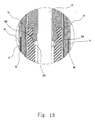
- a cylindrical slider 92 is set between the middle and rear barrels 12 and 15 as shown in Fig. 13. This slider 92 comes into contact with the rear end of the front barrel 13 when the rear barrel 15 is moved fully forward on the middle barrel 12 so as to completely cover the middle barrel 12.
- the external surface of the middle barrel 12 is protected from frictional damage, such as scratching, during an axial movement of the rear barrel 15 on the middle barrel 12.
- the cylindrical slider 92 is also preferably chromed, thus being effectively protected from frictional damage during an 16 axial movement of the rear barrel 15 on the middle barrel 12.
- the makeup brush 33 such as a loose powder brush, a fan brush, a lip brush, a mascara brush, an eyeliner brush, or a brow brush, is held on the front tip of the brush holder 18 mounted to the front end of the thrust rod 31.
- the thrust rod 31 has the cylindrical boss 322 at its rear end portion, with the external spiral thread 321 being formed on the external surface of the boss 322.
- the rear barrel 15 having the cap 16 is moved backward on the middle barrel 12 from the front barrel 13 as shown in Fig. 4 while gripping the front and rear barrels 13 and 15 with two hands of a user. Therefore, the rotatable rod 110, movably engaging with the cap 16 through a screw-type engagement, is rotated by the backward movement of the rear barrel 15. Due to such a rotating action of the rotatable rod 110, the thrust rod 31 is moved forward since the external spiral thread 321, formed at cylindrical boss 322 of the thrust rod 31, movably engages with the internal spiral thread 221 formed at the cylindrical seat 124 of the rotatable rod 110.
- the makeup brush 33 is fully projected from the front opening of the casing, thus allowing the user to use the brush 33.
- the rear barrel 15 is fully moved forward on the middle barrel 12 until the rear barrel 15 completely covers the middle barrel 12. In such a case, the front and rear barrels 13 and 15 are gripped with two hands of the user.
- the thrust rod 31 is moved backward within the casing, and so the makeup brush 33 is fully retracted into the front barrel 13 of the casing, thus being stored within the casing.
- the cap 16 When the rear barrel 15 is moved backward on the middle barrel 12 to project the brush 33 from the casing, the cap 16 is moved along with the rear barrel 15 in the same direction since the cap 16 is integrated with the barrel 15. In such a case, the external surface of the middle barrel 12 is exposed to the atmosphere, with the length of the casing being increased to accomplish a maximum length. However, when the rear barrel 15 is moved forward on the middle barrel 12 to fully cover the middle barrel 12 and to fully retract the brush 33 into the casing, the length of the casing is reduced to accomplish a minimum length.
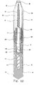
- Fig. 6 is a sectional view of a hand-held multipurpose casing, having a screw-type actuating unit and used as a writing instrument casing, in accordance with the second embodiment of the present invention.
- Fig. 7 is an exploded perspective view of the hand-held multipurpose casing of Fig. 6.
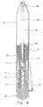
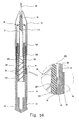
- Fig. 8 is a sectional view of a hand-held multipurpose casing, having a screw-type actuating unit and used as a writing instrument casing, in accordance with the fourth embodiment of the present invention.
- Fig. 9 is an exploded perspective view of the hand-held multipurpose casing of Fig. 8.
- the profile of the hand-held multipurpose casing according to the second embodiment of this invention is formed by a hollow cylindrical front barrel 13, having an internal thread 19 at its rear end with a conical front end, a hollow middle barrel 12, and a hollow rear barrel 15.
- a cap 16 is fixedly fitted into the rear end of the cylindrical rear barrel 15.
- the multipurpose casing of this invention houses a screw-type actuating unit used for projecting or retracting a writing point 33 relative to the casing.
- the screw-type actuating unit housed within the multipurpose casing according to the second embodiment, comprises a point holder 18, which has a point 33 at its front end and an internally threaded hole 19' at its rear end.
- the actuating unit also has a packing plug 14, having an external thread 41 on its external surface.
- This plug 14 engages with the front barrel 13 through a screw-type engagement of its external thread 41 with the internal thread 19 of the front barrel 13.
- the packing plug 14 is centrally holed to have a central hole, with both an annular fitting groove 42 formed on the internal surface of the holed plug 14 and two axial guide grooves 114 formed along the internal surface of the plug 14 at diametrically opposite positions.
- a thrust rod 8 having an external thread 41' at its front end, is coupled to the point holder 18 through a screw-type engagement of its external thread 41' with the internally threaded hole 19' of the point holder 18.
- the above thrust rod 8 also has a cylindrical boss 322 at its rear end portion, with an external spiral thread 321 being formed on the external surface of the boss 322.
- Two guide rails 113 are axially formed along the external surface of the thrust rod 8 at diametrically opposite positions.
- the cylindrical boss 322 of the thrust rod 8 is inserted into a cup-shaped cylindrical seat of a rotatable rod 9.
- the cylindrical seat is integrated with the front end of a longitudinal actuating part 112 having an external spiral thread 321'.
- the cup-shaped cylindrical seat of the rotatable rod 9 also has an internal spiral thread 111 on its internal surface, with a stop groove 44 formed at the front end of the internal spiral thread 111 of the cylindrical seat and used for preventing an undesired movement of the thrust rod 8.
- the longitudinal actuating part 112 of the rotatable rod 9 engages with a cylindrical cap rod 10.
- a guide groove 47 is axially formed along the external surface of the centrally holed cap rod 10.
- an external thread 41" is formed at the rear end portion of the external surface of the cap rod 10, while an internal spiral thread 111' is formed on the internal surface of the cap rod 10.
- the middle barrel 12 is fixedly fitted into the rear end of the front barrel 13 at its front end portion, and is movably fitted into the front end of the rear barrel 15 at its rear end portion.
- the above middle barrel 12 has a partition ring 43' on its external surface so as to separate the front and rear barrels 13 and 15 from each other.
- a guide projection 46 is axially formed on the internal surface of the middle barrel 12, and movably engages with the axial guide groove 47 of the cap rod 10. Due to the movable engagement of the guide projection 46 of the middle barrel 12 with the guide groove 47 of the cap rod 10, it is possible to prevent an undesired rotating action of the cap rod 10 relative to the middle barrel 12.
- the rear barrel 15 is movably fitted over the rear portion of the middle barrel 12 so as to be moved on the middle barrel 12 in opposite directions as desired.
- the cap 16 is fixedly fitted into the rear end of the cylindrical rear barrel 15.
- This cap 16 also has an internally threaded hole 19" at its front end, and is integrated with the cap rod 10 through a screw-type engagement of its internally threaded hole 19" with the external thread 41" of the cap rod 10.
- the multipurpose casing of this embodiment also has a clip 45, of which the ring 56 is fitted over the cap 16 while being compressed between the rear end of the rear barrel 15 and an external annular seat of the cap 16.
- the point 33 may be selected from the points of a variety of pens, such as felt tip point pens.
- the rotatable rod 9 is assembled with the cap rod 10 by making the external spiral thread 321' of the rotatable rod 9 movably engage with the internal spiral thread 111' of the cap rod 10.
- the thrust rod 8 is coupled to the rotatable rod 9 by inserting the cylindrical boss 322 of the thrust rod 8 into the cup-shaped cylindrical seat of the rotatable rod 9.
- the external spiral thread 321 of the cylindrical boss 322 movably engages with the internal spiral thread 111 formed on the internal surface of the cylindrical seat of the rotatable rod 9.
- the packing plug 14 is fitted over the front end portion of the rotatable rod 9, with the fitting groove 57 of the plug 14 engaging with the fitting ring 43 of the rotatable rod 9.
- the external thread 41' of the thrust rod 8 engages with the internally threaded hole 19' of the point holder 18, thus assembling the thrust rod 8 with the point holder 18.
- the middle barrel 12 is fitted over the cap rod 10.
- the front barrel 13 is fixedly fitted over the front portion of the middle barrel 12, while the rear barrel 15 is movably fitted over the rear portion of the middle barrel 12 so as to be movable on the middle barrel 12 in opposite directions as desired.
- the front barrel 13 is fixed to the packing plug 14, and so the point holder 18 linearly moves in an axial direction in response to a rotating action of the rotatable rod 9.
- the thrust rod 8 since the guide rails 113 of the thrust rod 8 movably engage with the guide grooves 114 of the packing plug 14, the thrust rod 8 is stably movable within the fixed packing plug 14 in an axial direction under the guidance of the guide grooves 114 of the plug 14.
- the guide projection 46 of the middle barrel 12 movably engages with the axial guide groove 47 of the cap rod 10, thus preventing an undesired rotating action of the cap rod 10 relative to the middle barrel 12.
- the rear barrel 15 having the cap 16 is moved backward on the middle barrel 12 from the front barrel 13 while gripping the front and rear barrels 13 and 15 with two hands of a user. Therefore, the cap rod 10 integrated with the cap 16 is moved in the same direction.
- the rotatable rod 9, movably assembled with the cap rod 10 through a screw-type engagement, is rotated clockwise.
- the thrust rod 8 Due to such a clockwise rotating action of the rotatable rod 9, the thrust rod 8 is axially moved forward since the external spiral thread 321 of the thrust rod 8 movably engages with the internal spiral thread 111 of the rotatable rod 9.
- the point 33 is fully projected from the front opening of the casing, thus allowing the user to use the point 33 of the writing instrument.
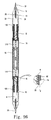
- a longitudinal ballpoint pen cartridge 33 is used in place of the point of the third embodiment as shown in Figs. 8 and 9.
- the longitudinal cartridge 33 is provided with two spring stoppers 101.
- the two spring stoppers 101 are formed on the front portion of the external surface of the cartridge 33 at diametrically opposite positions.
- a compression coil spring 100 is movably fitted over the cartridge 33 at the front portion so as to be stopped by the spring stoppers 101.
- the spring 100 thus normally biases the cartridge 33 backward so as to allow the cartridge 33 to be normally retracted into the casing.
- the rear end of the cartridge 33 is inserted into the front end of the thrust rod 8.
- a sharpened cartridge holder 52 is fixedly formed within the thrust rod 8, and holds the rear end of the cartridge 33 within the thrust rod 8.
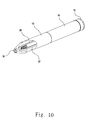
- Fig. 10 is a perspective view of a hand-held multipurpose casing, having a screw-type actuating unit and used as a makeup brush casing, in accordance with the fourth embodiment of the present invention, particularly showing an automatically operated brush cover set within the casing.
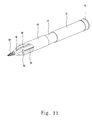
- Fig. 11 is a perspective view showing an operation of the hand-held multipurpose casing of Fig.10
- the front end portion of the middle barrel 15 is fixedly fitted into the rear end portion of the front barrel 13, while the rear end portion of the middle barrel 12 is movably fitted into the front end portion of the rear barrel 15.
- a cap 16 is fixedly fitted into the rear end of the cylindrical rear barrel 15.
- the multipurpose casing of this embodiment houses a screw-type actuating unit used for projecting or retracting a makeup brush 33 relative to the casing.
- the rear barrel 15 is movably fitted over the rear end portion of the middle barrel 12 as described above, and so the rear barrel 15 is axially slidable on the middle barrel 12 in opposite directions as desired.
- the casing has an automatically operated brush cover, comprising two cover members 30 and 32 extending along the brush holder 18 at diametrically opposite positions within the casing.
- the above brush cover is used for preventing an undesired introduction of foreign substances, such as dust, into the interior of the casing.
- Fig. 12 is sectional view of the hand-held multipurpose casing of Fig. 10.
- Fig. 13 is a sectional view of the portion "A" of Fig. 12.
- Fig. 14 is a sectional view showing the operation of the hand-held multipurpose casing of Fig. 10.
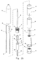
- Fig. 15 is an exploded perspective view of the hand-held multipurpose casing of Fig. 10.
- the screw-type actuating unit housed within the multipurpose casing according to the sixth embodiment, comprises a rotatable rod 110, a packing plug 120, a thrust rod 31, two cover members 30 and 32, and a brush holder 18.
- the rotatable rod 110 consists of a cup-shaped cylindrical seat 124 integrated with the front end of a longitudinal actuating part 112 having an external spiral thread 111.
- the cup-shaped cylindrical seat 124 has an internal spiral thread 221 on its internal surface, with an annular fitting groove 131 formed at the front portion of said internal surface.
- the packing plug 120 is a centrally and axially holed member, with two guide slots 211 being axially formed on the external surface of the plug 120 at diametrically opposite positions.
- a fitting ring 122 is formed on the external surface of the packing plug 120 at a rear portion. This fitting ring 122 engages with the fitting groove 131 of the rotatable rod 110, thus accomplishing a desired engagement of the packing plug 120 with the rotatable rod 110.
- Two guide grooves 114 are axially formed on the internal surface of the holed plug 120 at diametrically opposite positions.
- the thrust rod 31 has a cylindrical boss 322 at its rear end portion, with an external spiral thread 321 being formed on the external surface of the boss 322.
- the above thrust rod 31 also has two axial guide rails 113 on its external surface at diametrically opposite positions so as to movably engage with the guide grooves 114 of the packing plug 120.
- the thrust rod 31 is inserted into the cylindrical seat 124 of the rotatable rod 110 and is axially movable in accordance with a rotating action of the rotatable rod 110 due to the movable engagement of its external thread 321 with the internal thread 221 of the rotatable rod 110.
- the brush holder 18 is mounted to the front end of the thrust rod 31 and holds the makeup brush 33 at its front tip.
- the cap 16 has a central hole closed at its rear end, with two guide projections 55 being formed on the internal surface of the cap 16 at diametrically opposite positions.
- the two guide projections 55 of the cap 16 movably engage with the external thread 111 formed on the longitudinal actuating part 112 of the rotatable rod 110.
- the cap 16 also has the two holding slots 42 at diametrically opposite positions on its external surface, and holds the two cover members 30 and 32 at the two holding slots 42.
- the above cap 16 also has an annular support seat 43 at the rear portion of its external surface.
- the two cover members 30 and 32 have the same construction and individually comprise a longitudinal guide part, with both a semicircular cover part 36 formed at the front end of the guide part and a bend projection 34 formed at the rear end of the guide part.
- the cover parts 36 of the two cover members 30 and 32 are automatically closed, thus closing the interior of the casing and preventing an undesired introduction of foreign substances into the casing.
- the thrust rod 31 axially moves forward to project the makeup brush 33 from the front opening of the front barrel 13
- the cover parts 36 of the two cover members 30 and 32 are automatically opened to allow the thrust rod 31 to pass through the gap between the two cover parts 36.
- the two cover members 30 and 32 are mounted to the two holding slots 42 of the cap 16 at their bent projections 34, and so the cover members 30 and 32 are prevented from an undesired rotating action within the casing.
- the longitudinal guide parts of the two cover members 30 and 32 axially extend forward along each side of the thrust rod 31 while passing through the two guide slots 211 of the packing plug 120.
- the hollow front barrel 13 has a cylindrical shape with a conical front end, and covers the front and middle portions of each of the two cover members 30 and 31.
- the hollow middle barrel 12, having a cylindrical shape, is firmly fitted into the rear end of the front barrel 13 and houses both the packing plug 120 and the front and middle portion of the rotatable rod 110 therein. In such a case, the internal surface of the middle barrel 12 comes into close contact with the external surfaces of the two cover members 30 and 32 at diametrically opposite positions.
- the hollow rear barrel 15 is movably fitted over the middle and rear portion of the middle barrel 12 at its front portion, and is firmly fitted over the cap 16 at its rear portion, with the rear end of the rear barrel 15 being firmly seated on the annular support seat 43 of the cap 16. Due to the firm engagement of the rear barrel 15 with the cap 16, the rear barrel 15 is movable along with the cap 16.
- the guide projections 55 formed on the internal surface of the cap 16, movably engage with the external thread 111 formed on the longitudinal actuating part 112 of the rotatable rod 110.
- the spiral direction of the external thread 321 of the thrust rod 31 is opposite to that of the external thread 111 of the rotatable rod 110. Due to such a movable engagement of the projections 55 of the cap 16 with the external thread 111 of the rotatable rod 110, the rotatable rod 110 is rotated when the rear barrel 15 with the cap 16 is axially moved relative to the middle barrel 12.
- Such a rotating action of the rotatable rod 110 creates an axial movement of the thrust rod 31 within the casing due to a movable engagement of the internal spiral thread 221 of the rotatable rod 110 with the external spiral thread 321 of the thrust rod 31, thus finally allowing the makeup brush 33 of the brush holder 18 to be projected from or retracted into the front hole of the front barrel 13.
- the fitting ring 122 formed on the external surface of the packing plug 120 at the rear portion, engages with the fitting groove 131 of the rotatable rod 110, thus holding the axial position of the rotatable rod 110 within the casing. Therefore, the axial movement of the rear barrel 15 relative to the middle barrel 12 is completely converted into a desired rotating action of the rotatable rod 110.
- an annular fitting groove 131 is formed at the front portion of the internal surface of the cup-shaped cylindrical seat 124.
- the packing plug 120 varies in its diameter in such a way that the diameter of the rear portion of the plug 120 having the fitting ring 122 is smaller than that of the front portion of the plug 120. Therefore, it is possible to desirably reduce the frictional force between the fitting ring 122 of the plug 120 and the fitting groove 131 of the rotatable rod 110 during an axial movement of the thrust rod 31 within the packing pump 120.
- the cap 16 has a U-shaped cross-section when cutting the cap 16 in an axial direction.
- the two guide projections 55 are formed on the internal surface at diametrically opposite positions, and movably engage with the external spiral thread 111 formed on the longitudinal actuating part 112 of the rotatable rod 110.
- the rear barrel 15 is integrated with the cap 16, the rear end of barrel 15 is firmly seated on the annular support seat 43 of the cap 16.
- the cap 16 is movable along with the rear barrel 15.
- the two cover members 30 and 32 are made of an elastic material capable of allowing the members 30 and 32 to be elastically deformed as desired. That is, when the rear barrel 15, integrated with the cap 16, is moved backward on the middle barrel 12 so as to axially move the thrust rod 31 forward and to project the makeup brush 33 from the front opening of the front barrel 13, the two cover members 30 and 32 automatically and elastically open their cover parts 36 to allow the thrust rod 31 to pass through the gap between the two cover parts 36.
- the cover parts 36 of the two cover members 30 and 32 move toward the conical front end of the front barrel 13 and are automatically and elastically closed, thus closing the interior of the casing and preventing an undesired introduction of foreign substances into the casing.
- the closed cover parts 36 of the two cover members 30 and 32 also protect the fully retracted makeup brush 33 from damage. Due to the two cover members 30 and 32, it is not necessary for the casing of this embodiment to have a conventional separate protective cap, and so the casing of this embodiment saves a user from the inconvenience caused by losing the separate protective cap.
- each of the bent projections 34 may be bent once or more as desired if the projections 34 are firmly held to the holding slots 42 of the cap 16 without being undesirably removed from the slots 42.
- the two holding slots 42 are formed on the front end portion of the external surface of the cap 16 at diametrically opposite positions, thus firmly holding the bent projections 34 of the two cover members 30 and 32. Therefore, the packing plug 120 prevents an undesired rotating action of the two cover members 30 and 32 even though a user carelessly attempts to rotate the rear barrel 15 with the cover members 30 and 32 during an operation of the casing.
- the casing of this embodiment thus only allows the user to project or retract the makeup brush 33 from or into the front opening of the front barrel 13.
- the cap 16 may be preferably made of metal. However, it should be understood that the cap 16 may be also preferably made of plastic, rubber or silicon in addition to metal. Such a plastic, rubber or silicon cap 16 is light and allows a user to feel a soft surface while using the casing.
- the front barrel 13 has a hollow cylindrical shape with a conical front end and houses the cover members 30 and 32 therein. This front barrel 13 fixedly receives the front end portion of the middle barrel 12.
- the middle barrel 12 having a hollow cylindrical shape, is firmly fitted into the rear end of the front barrel 13, and comes into close contact with the external surfaces of the two cover members 30 and 32 at its internal surface. Therefore, the inner diameter of the middle barrel 12 is not smaller than a diameter formed by the two cover members 30 and 32.
- the outer diameter of the rear portion of the middle barrel 12 is sufficiently smaller than the inner diameter of the rear barrel 15 as to allow the rear barrel 15 to smoothly move relative to the middle barrel 12 during an axial movement of the rear barrel 15.
- the front portion of the rear barrel 15, fitted over the rear portion of the middle barrel 12 is not fixed to the middle barrel 12, but is smoothly movable relative to the middle barrel 12 even though it comes into close contact with the external surface of the middle barrel 12.
- the external surface of the middle barrel 12 is exposed to the atmosphere.
- the external surface of the middle barrel 12 is completely covered by both the front barrel 13 and the rear barrel 15 when fully retracting the makeup brush 33 into the casing.
- a cylindrical slider 92 is set between the middle and rear barrels 12 and 15 as shown in Fig. 13. This slider 92 comes into contact with the rear end of the front barrel 13 when the rear barrel 15 is fully moved forward on the middle barrel 12 so as to completely cover the middle barrel 12.
- the external surface of the middle barrel 12 is protected from frictional damage, such as scratching, during an axial movement of the rear barrel 15 on the middle barrel 12.
- the cylindrical slider 92 is also preferably chromed, thus being effectively protected from frictional damage during an axial movement of the rear barrel 15 on the middle barrel 12.
- the makeup brush 33 such as a loose powder brush, a fan brush, a lip brush, a mascara brush, an eyeliner brush, or a brow brush, is held on the front tip of the brush holder 18 mounted to the front end of the thrust rod 31.
- the thrust rod 31 has the cylindrical boss 322 at its rear end portion, with the external spiral thread 321 being formed on the external surface of the boss 322.
- the rear barrel 15 having the cap 16 is moved backward on the middle barrel 12 from the front barrel 13 as shown in Fig. 14 while gripping the front and rear barrels 13 and 15 with two hands of a user. Therefore, the rotatable rod 110, movably engaging with the cap 16 through a screw-type engagement, is rotated by the backward movement of the rear barrel 15. Due to such a rotating action of the rotatable rod 110, the thrust rod 31 is axially moved forward since the external spiral thread 321, formed at the cylindrical boss 322 of the thrust rod 31, movably engages with the internal spiral thread 221 formed at 45 the cylindrical seat 124 of the rotatable rod 110. Therefore, the makeup brush 33 is fully projected from the front opening of the casing, thus allowing the user to use the brush 33.
- the rear barrel 15 is fully moved forward on the middle barrel 12 until the rear barrel 15 completely covers the middle barrel 12. In such a case, the front and rear barrels 13 and 15 are gripped with two hands of the user.
- the thrust rod 31 is moved backward within the casing, and so the makeup brush 33 is fully retracted into the front barrel 13 of the casing, thus being stored within the casing.
- the cap 16 When the rear barrel 15 is moved backward on the middle barrel 12 to project the brush 33 from the casing, the cap 16 is moved along with the rear barrel 15 in the same direction since the cap 16 is integrated with the barrel 15. In such a case, the external surface of the middle barrel 12 is exposed to the atmosphere, with the length of the casing being increased to accomplish a maximum length. However, when the rear barrel 15 is moved forward on the middle barrel 12 to fully cover the middle barrel 12 and to fully retract the brush 33 into the casing, the length of the casing is reduced to accomplish a minimum length.
- Fig. 16 is a sectional view of a hand-held multipurpose casing, having a screw-type actuating unit and used as a makeup brush casing, in accordance with the fifth embodiment of the present invention.
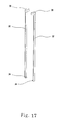
- Fig. 17 is a perspective view of the brush cover according to this invention.
- Fig. 18 is a perspective view of an automatically operated brush cover in accordance with another embodiment of this invention.
- the unit for converting the axial linear movement of the cap 16 into a rotating action of the rotatable rod 110 is altered by making the rotatable rod 110 having a simple hollow cylindrical shape without the longitudinal actuating part 112 different from the embodiment of Figs. 17 to 20.
- the rotatable rod has internal and external spiral threads 221 and 222 on its internal and external surfaces, with the spiral directions of the two threads 221 and 22 being opposite to each other.
- the diameter of the external spiral thread 222, formed on the external surface of the rotatable rod 110 is larger than that of the sixth embodiment.
- the interior surface of the cap 16 is stepped to enlarge the inner diameter of the cap 16.
- the two projections 55 are formed on the stepped internal surface of the cap 16 at a front portion.
- Fig. 17 shows the configuration of two protective cover members 30 and 32 in accordance with an embodiment of this invention
- Fig. 18 shows the configuration of two protective cover members 30 and 32 in accordance with another embodiment.
- the two cover members 30 and 32 having the same construction, individually have a semicircular cover part 36 formed at the front end of a longitudinal guide part.
- the cover parts 36 of the two cover members 30 and 32 are selectively closed or opened in accordance with an axial linear movement of the cap 16.
- the two cover members 30 and 32 are movable in an axial direction within the casing in response to an axial movement of the cap 16 without coming into frictional contact with the internal surface of the front barrel 13.
- the two cover members 30 and 32 are made of an elastic material capable of allowing the longitudinal guide part of each cover member 30 or 32 to be elastically deformed during an operation of the casing.
- Each of the two cover members 30 and 32 has one bent projection 34 at its rear end, and is held on the cap 16 at the bent projection 34.
- the bent projection 34 is formed by bending the rear end of the longitudinal guide part of each cover member 30 or 32 at a right angle.
- each cover member 30 or 32 remains the same as that of the embodiment of Fig. 22, but the axial length of the semicircular cover part 37 is longer than that of the part 36 and two projections 5 are formed at the rear end of each cover member 30 or 32 different from the embodiment of Fig. 17. Due to the projections 5 of Fig. 18, it is possible to more firmly hold the cover members 30 and 32 within the casing.
- the facing surfaces of the two cover parts are flat.
- the two cover parts may be designed to have another shape on their facing surfaces, for example, rounded surfaces, V-grooved surfaces, or U-grooved surfaces, without affecting the functioning of this invention.
- Fig. 19 is an exploded perspective view, showing the construction of a rotatable rod assembly consisting of a rotatable rod and a rod guide tube used in the screw-type hand-held multipurpose casing of the present invention.
- Fig. 20 is a perspective view of the rotatable rod assembly of Fig. 19.
- Fig. 21 is a perspective view, showing an operation of the rotatable rod assembly of Fig. 20.
- the cup-shaped cylindrical seat 124 of the rotatable rod 79 has a fitting ring 60 on its external surface.
- the cylindrical seat 124 is integrated with the front end of a longitudinal actuating part having an external spiral thread 64, with a slit fixing tip 62 being provided at the rear end of the longitudinal actuating part.
- the cup-shaped cylindrical seat 124 of the rotatable rod 79 also has an internal spiral thread 74 on its internal surface, with a stop groove 44 formed at the front end of the internal spiral thread 74 and used for preventing an undesired movement of the makeup brush.
- the spiral directions of the external and internal threads 64 and 74 of the rotatable rod 79 are opposite to each other.
- the above rotatable rod 79 engages with a cylindrical cap rod 77.
- a guide groove 47 is axially formed along the external surface of the centrally holed cap rod 77.
- two slots 68 are formed on the front end of the external surface of the cap rod 77 at diametrically opposite positions.
- the above cap rod 77 is centrally and axially holed, with an internal spiral thread 70 being formed on the internal surface of the cap rod 77.
- the longitudinal actuating part of the rotatable rod 79 is axially inserted into the central hole of the cap rod 77.
- the external spiral thread 64 of the rotatable rod 79 movably engages with the internal spiral thread 70 of the cap rod 77. Therefore, the rotatable rod 79 is rotated in response to an opposite directional axial movement of the cap rod 77.
- a guide projection 46 is axially formed on the internal surface of the middle barrel 76 at the rear end portion, and movably engages with the axial guide groove 47 of the cap rod 77. Due to the movable engagement of the guide projection 46 of the middle barrel 76 with the guide groove 47 of the cap rod 77, it is possible to prevent an undesired rotating action of the cap rod 77 relative to the middle barrel 76.
- the movable engagement of the guide projection 46 of the middle barrel 76 with the guide groove 47 of the cap rod 77 prevents an undesired rotating action of the cap rod 77 relative to the middle barrel 76.
- the slit fixing tip 62 of the rotatable rod 79 is coupled to the cap rod 77, and allows the rotatable rod 79 to be rotated relative to the cap rod 77.
- the cylindrical seat 124 of the rotatable rod 79 is fitted into the rear end of a brush holder unit 80. That is, the above brush holder unit 80 has an axial hole at its rear end and receives the cylindrical seat 124 of the rotatable rod 79 in the axial hole. In such a case, an annular fitting groove is formed on the internal surface of the axial hole of the brush holder unit 80, and engages with the fitting ring 60 of the rotatable rod 79.
- the above brush holder unit 80 comprises two brush holders 84.
- the two brush holders 84 define a brush holding slot (not shown) and support a desired brush at the brush holding slot.
- An axial slot 82 is formed on the external surface of the lower portion of the brush holder unit 80.
- Figs. 19 to 21 having the stop groove 44, the guide projection 46 and the guide groove 47, may be preferably used as a hand-held casing for a pen cartridge or a painting brush in addition to a makeup brush.
- Fig. 22 is a sectional view of a hand-held multipurpose casing, having a screw-type actuating unit and used as a writing instrument casing with an automatically operated cartridge cover set within the casing, in accordance with the sixth embodiment of the present invention.
- Fig. 23 is an exploded perspective view showing the construction of the hand-held multipurpose casing of Fig. 22.
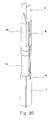
- Fig. 24 is a sectional view of a hand-held multipurpose casing, having a screw-type actuating unit and used as a writing instrument casing with a ballpoint pen cartridge, in accordance with the seventh embodiment of the present invention.
- Fig. 25 is an exploded perspective view showing the construction of the hand-held multipurpose casing of Fig. 24.
- the general shape of the casing remains the same as that described for the embodiment of Figs. 6 and 7, but two protective cover members 30 and 32 axially extend within the casing at diametrically opposite positions.
- the bent projection 34 of each of the two cover members 30 and 32 is fixedly held in the slot 42 of the cap rod 10, and so the two cover members 30 and 32 are movable along with the cap rod 10.
- the two cover members 30 and 32 are fixedly held on the cap rod 10, and so the two cover members 30 and 32 are movable along with the cap rod 10.
- Fig. 26 is a sectional view of a hand-held multipurpose casing, having two screw-type actuating units at opposite end portions of the casing and used as a makeup brush casing, in accordance with the eighth embodiment of the present invention.
- the general shape of the casing comprising a packing plug 120, two protective cover members 30 and 32, three barrels 12, 13 and 15, a cylindrical slider 92, and a brush holder 18, remains the same as that described for the embodiment of Fig. 14, but the structure of both the rear part of the rotatable rod 110 and the front part of the cap 16 is altered.
- the structural alteration of both the rod 110 and the cap 16 generally remains the same as that described for the embodiment of Fig. 16, but two screw-type actuating units are symmetrically provided within opposite end portions of the casing.
- the actuating unit for converting the axial linear movement of the cap 16 into a rotating action of the rotatable rod 110 is altered by making the rotatable rod 110 having a simple hollow cylindrical shape without the longitudinal actuating part 112.
- the above rotatable rod 110 has internal and external spiral threads on its internal and external surfaces, with the spiral directions of the two spiral threads being opposite to each other.
- the external spiral thread has a larger diameter.
- the interior surface of the cap 16 is stepped to enlarge the inner diameter of the cap 16, with the two projections being formed on the stepped internal surface of the cap 16 at a front portion.
- two actuating units are symmetrically provided at opposite ends of one cap 16, and so the casing may be provided with two makeup brushes actuated by the two actuating units.
- the casing of this embodiment may be provided with two points of pen cartridges in place of the two makeup brushes.
- the casing may have a point of a pen cartridge actuated by one actuating unit and a makeup brush actuated by the other actuating unit.
- the eighth embodiment is formed by altering the construction of the embodiment of Fig. 16, but it should be understood that the other embodiments of this invention may be changed in its construction to have two actuating units.
- the present invention provides a hand-held multipurpose casing, having a cylinder-type or screw-type actuating unit for reversibly extending a functional tipped device housed within the casing, for example, a ballpoint pen cartridge or a makeup brush.
- This hand-held multipurpose casing has a cylinder-type or screw-type actuating unit capable of reversibly extending such a functional tipped device.
- the casing of this invention is thus reduced in the number of parts and has a simple construction, thereby being easily produced and repaired while reducing the production and repair cost and conserving labor. This casing also allows a user to purchase it at low cost.
- the casing of this invention Different from conventional casings for such makeup brushes or writing instruments, it is not necessary for the casing of this invention to have a removable separate cap, but an automatically operated protective cover is set within the casing.
- the casing of this invention thus saves a user from the inconvenience of losing a conventional removable cap, and the inconvenience of being stained with cosmetics of the makeup brush.
- Due to the protective cover the interior of the casing of this invention is effectively protected from foreign substances, such as dust. Since the protective cover is set within the casing and is automatically operated in response to an axial movement of a rear barrel relative to a middle barrel, it is possible for the user to easily operate the casing with one hand.
- the casing of this invention is less likely to be broken or damaged since it has a simple construction, and so it is usable for a desired lengthy period of time and is recyclable as desired.
- the casing of this invention is preferably usable as a casing for makeup brushes or a casing for writing instruments, such as ballpoint pens.
- the casing of this invention is reduced in the number of parts, and is easily assembled and disassembled when necessary. Due to the protective cover set within the casing, the interior of the casing is less likely to become contaminated with foreign substances, such as dust. The casing is also less likely to become frictionally damaged on its parts.
- the actuating unit smoothly extends or retracts a makeup brush or a point of a writing instrument by an opposite directional axial movement of a rear barrel along with a cap relative to a middle barrel.
- the cap It is also possible to press the cap against a support surface, such as the top surface of a desk, to fully retract the makeup brush or the point into the casing.
- the retraction of the makeup brush or the point into the casing can be accomplished by using one hand.
- the casing of this invention is less likely to be broken or damaged since it has a simple construction, and so it is usable for a desired lengthy period of time and is recyclable as desired.
- the external surface of the middle barrel is protected from frictional damage, such as scratching, during an axial movement of the rear barrel on the middle barrel.
- the above slider also allows the rear barrel to smoothly move on the middle barrel.
- the casing is adjustable in its length as desired. That is, when the rear barrel along with the cap is fully moved backward on the middle barrel, the casing has a maximum length. On the other hand, the casing has a minimum length when the rear barrel is fully moved forward on the middle barrel.
- the spiral direction of an external spiral thread of a thrust rod is opposite to that of the external spiral thread of a rotatable rod, and so the parts of the actuating unit are smoothly operated while being less likely to be broken.
Landscapes
- Engineering & Computer Science (AREA)
- Mechanical Engineering (AREA)
- Containers And Packaging Bodies Having A Special Means To Remove Contents (AREA)
- Coating Apparatus (AREA)
- Mechanical Pencils And Projecting And Retracting Systems Therefor, And Multi-System Writing Instruments (AREA)
- Brushes (AREA)
- Packages (AREA)
- Mutual Connection Of Rods And Tubes (AREA)
Claims (22)
- Tragbares Mehrzweckgehäuse, umfassend: einen vorderen Zylinder (13) mit einer vorderen Öffnung; einen hinteren Zylinder (15); und einen Halter (18) für eine funktionale spitz zulaufende Vorrichtung, der an seiner vorderen Spitze eine funktionale spitz zulaufende Vorrichtung (33) aufweist, wobei der Halter innerhalb des Gehäuses aufgenommen ist, um innerhalb des Gehäuses in Reaktion auf eine axiale Bewegung des hinteren Zylinders axial beweglich zu sein, wo durch die funktionale spitz zulaufende Vorrichtung aus der vorderen Öffnung des vorderen Zylinders vorgeschoben oder in diese hinein zurückgezogen wird, dadurch gekennzeichnet, dass das Gehäuse weiterhin umfasst:einen mittleren Zylinder (12) der an seinem vorderen Endabschnitt fest in einen hinteren Endabschnitt des vorderen Zylinders eingepasst ist, wobei der hintere Zylinder (15) an seinem vorderen Endabschnitt beweglich über einen hinteren Endabschnitt des mittleren Zylinders gepasst ist, um axial auf dem mittleren Zylinder beweglich zu sein;eine Kappe (16),die fest an einem hinteren Ende des hinteren Zylinders angebracht ist, wobei zwei Halteschlitze (42) an einem vorderen Endabschnitt einer externen Oberfläche der Kappe in diametral entgegengesetzten Positionen ausgebildet sind; undeine schraubenartige Betätigungseinheit (110, 120, 31, 115), die über zwei spiralförmige schraubenartige Eingriffe mit entgegengesetzten Spiralrichtungen sowohl mit dem Halter für eine funktionale spitz zulaufende Vorrichtung als auch mit der Kappe in beweglichem Eingriff steht, wobei die Einheit primär eine axiale Bewegung der Kappe in eine Drehwirkung einer drehbaren Stange (110) umwandelt und sekundär die Drehwirkung der drehbaren Stange in eine axiale Bewegung des Halters (18) für eine funktionale spitz zulaufende Vorrichtung umwandelt und dadurch die funktionale spitz zulaufende Vorrichtung aus der vorderen Öffnung des vorderen Zylinders heraus vorschiebt oder in diese hinein zurückzieht.
- Tragbares Mehrzweckgehäuse nach Anspruch 1, weiterhin umfassend zwei Schutzabdeckungsglieder (30, 32), welche dieselbe Konstruktion aufweisen, wobei die beiden Abdeckungsglieder individuell einen Längsführungsteil umfassen, wobei sowohl ein Abdeckungsteil (36) als auch ein gebogener Vorsprung (34) an entgegengesetzten Enden des Führungsteils ausgebildet sind, wobei die beiden Abdeckungsglieder durch die Halteschlitze der Kappe an den gebogenen Vorsprüngen gehalten werden und sich axial innerhalb des Gehäuses nach vorne erstrecken, um gemeinsam mit der Kappe in derselben Richtung wie die Kappe beweglich zu sein und dadurch die vordere Öffnung des vorderen Zylinders selektiv zu verschließen oder zu öffnen.
- Tragbares Mehrzweckgehäuse nach Anspruch 2, wobei die Betätigungseinheit einen mittig und axial gelochten Dichtungsstöpsel (120) aufweist, wobei zwei Führungsschlitze (211) axial auf einer äußeren Oberfläche des Stöpsels in diametral entgegengesetzten Positionen ausgebildet sind und die Längsführungsteile der Abdeckungsglieder beweglich au fnehmen, wobei zwei Führungsrillen (114) axial an einer inneren Oberfläche des Stöpsels in diametral entgegengesetzten Positionen ausgebildet sind und ein Passring (122) an der äußeren Oberfläche des Stöpsels an einen hinteren Abschnitt ausgebildet ist.
- Tragbares Mehrzweckgehäuse nach Anspruch 3, wobei die Betätigungseinheit weiterhin eine Druckstange (31) umfasst, welche mit zwei axialen Führungsschienen (113) an ihrer äußeren Oberfläche in diametral entgegengesetzten Positionen versehen ist, wobei die Führungsschienen beweglich mit den beiden Führungsrillen (114) des Dichtungsstöpsels in Eingriff stehen und dadurch ermöglichen, dass die Druckstange axial beweglich ist.
- Tragbares Mehrzweckgehäuse nach Anspruch 1 oder 2, weiterhin umfassend einen zylindrischen Schieber (92), der zwischen dem mittleren und dem hinteren Zylinder angeordnet ist, um die äußere Oberfläche des mittleren Zylinders während einer axialen Bewegung des hinteren Zylinders auf dem mittleren Zylinder zu schützen.
- Tragbares Mehrzweckgehäuse nach Anspruch 1 oder 2, wobei die funktionale spitz zulaufende Vorrichtung ein Makeup-Pinsel ist, der aus der Gruppe umfassend Pinsel für loses Puder, Fächerpinsel, Lippenpinsel, Mascara - Pinsel, Eyeliner -Pinsel und Augenbrauenpinsel ausge - wählt wird.
- Tragbares Mehrzweckgehäuse nach Anspruch 1 oder 2, weiterhin umfassend einen Bügel (45), welcher einem Benutzer ermöglicht, das Gehäuse an einem Rand einer Tasche festzumachen.
- Tragbares Mehrzweckgehäuse, umfassend einen vorderen Zylinder (13) mit einer vorderen Öffnung; einen hinteren Zylinder (15); eine funktionale spitz zulaufende Vorrichtung (33), die innerhalb des Gehäuses aufge - nommen ist, um innerhalb des Gehäuses in Reaktion auf eine axiale Bewegung des hinteren Zylinders axial beweglich zu sein, und eine Betätigungseinheit (8, 9, 10, 14), die zum axialen Bewegen der funktionalen spitz zulaufenden Vorrichtung in Reaktion auf die axiale Bewegung des hinteren Zylinders verwendet wird, wodurch die funktionale spitz zulaufende Vorrichtung aus der vorderen Öffnung des vorderen Zylinders vorgeschoben oder in diese hinein zurückgezogen wird, dadurch gekennzeichnet, dass die Betätigungseinheit umfasst:einen mittleren Zylinder (12) der an seinem vorderen Endabschnitt fest in einen hinteren Endabschnitt des vorderen Zylinders eingepasst ist, wobei der hintere Zylinder (15) an seinem vorderen Endabschnitt beweglich über einen hinteren Endabschnitt des mittleren Zylinders gepasst ist, um axial auf dem mittleren Zylinder beweglich zu sein;eine drehbare Stange (9), die sowohl ein spiralförmiges Innengewinde an ihrem vorderen Endabschnitt als auch ein spiralförmiges Außengewinde (321) an ihrem hinteren Endabschnitt aufweist, wobei die Spiralrichtungen des spiralförmigen Innengewindes und des spiralförmigen Außengewindes einander entgegen gesetzt sind;eine Druckstange (8), welche an ihrem vorderen Ende die funktionale spitz zulaufende Vorrichtung hält und an ihrem hinteren Endabschnitt ein spiralförmiges Außengewinde (321') aufweist und mit der drehbaren Stange über einen schraubenartigen Eingriff zwischen dem spiralförmigen Außengewinde (321') der Druckstange und dem spiralförmigen Innengewinde (111) der drehbaren Stange beweglich in Eingriff steht, wodurch Drehung der drehbaren Stange in axiale Bewegung der Druckstange umgewandelt wird; undeine Kappenstange (10), die an ihrem vorderen Endabschnitt ein spiralförmiges Innengewinde (111) aufweist und mit der drehbaren Stange (9) über einen schraubenartigen Eingriff zwischen dem spiralförmigen Innengewinde (111) der Kappenstange und dem spiralförmigen Außengewinde (321) der drehbaren Stange beweglich in Eingriff steht, wodurch axiale Bewegung der Kappenstange in Drehung der drehbaren Stange umgewandelt wird, wobei die Kappenstange auch sowohl ein Außengewinde (41) an ihrer äußeren Oberfläche an einem hinteren Endabschnitt als auch eine Führungsrille (47), die axial entlang der äußeren Oberfläche der Kappenstange ausgebildet ist, aufweist.
- Tragbares Mehrzweckgehäuse nach Anspruch 8, weiterhin umfassend zwei Schutzabdeckungsglieder (30, 32), welche dieselbe Konstruktion aufweisen, wobei die beiden Abdeckungsglieder individuell einen Längsführungsteil umfassen, wobei sowohl ein Abdeckungsteil (36) als auch ein gebogener Vorsprung (34) an entgegengesetzten Enden des Führungsteils ausgebildet sind, wobei die beiden Abdeckungsglieder innerhalb des Gehäuses aufgenommen sind und gemeinsam mit dem hinteren Zylinder in dieselbe Richtung wie jene des hinteren Zylinders beweglich sind und dadurch die vordere Öffnung des vorderen Zylinders selektiv verschließen oder öffnen.
- Tragbares Mehrzweckgehäuse nach Anspruch 8 oder 9, wobei die Betätigungseinheit weiterhin einen mittig und axial gelochten Dichtungsstöpsel (14) umfasst, wobei ein Außengewinde (41) an einer äußeren Ober fläche des Dichtungsstöpsels an einem vorderen End abschnitt ausgebildet ist und zwei Führungsrillen (114) axial an einer inneren Oberfläche des Stöpsels in diametral entgegengesetzten Positionen ausgebildet sind und die Druckstange darin beweglich aufnehmen.
- Tragbares Mehrzweckgehäuse nach Anspruch 8 oder 9, wobei eine Anschlagrille (44) an einem vorderen Ende des spiralförmigen Innengewindes der drehbaren Stange zum Verhindern einer unerwünschten Bewegung de r Druckstange ausgebildet ist.
- Tragbares Mehrzweckgehäuse nach Anspruch 8 oder 9, wobei die Druckstange an ihrem vorderen Ende ein Außengewinde (41) aufweist und die funktionale spitz zulaufende Vorrichtung an ihrem hinteren Ende ein innen gewindetes Loch (19) aufweist und an dem innen gewindeten Loch an dem Außengewinde der Druckstange angebracht ist.
- Tragbares Mehrzweckgehäuse nach Anspruch 10, wobei der Dichtungsstöpsel über einen schraubenartigen Eingriff des Außengewindes des Dichtungsstöpsel s mit einem Innengewinde (19) des vorderen Zylinders (13) fest innerhalb des vorderen Zylinders angeordnet ist.
- Tragbares Mehrzweckgehäuse nach Anspruch 8 oder 9, wobei eine Kappe (16), welche eine innen gewindete Öffnung aufweist, auf das Außengewinde der Kappenstange (10) an deren innen gewindeter Öffnung festgezogen wird und dadurch mit der Kappenstange integriert wird.
- Tragbares Mehrzweckgehäuse nach Anspruch 8 oder 9, wobei die Druckstange (8) mit zwei axialen Führungsschienen (113) an ihr er äußeren Oberfläche an diametral entgegengesetzten Positionen versehen ist, wobei die Führungsschienen beweglich mit zwei Führungsrillen (114) eines Dichtungsstöpsels in Eingriff stehen und dadurch ermöglichen, dass die Druckstange axial beweglich ist.
- Tragbares Mehrzweckgehäuse nach Anspruch 8 oder 9, wobei der mittlere Zylinder (12) an seiner inneren Oberfläche an einem unteren Abschnitt einen axialen Führungsvorsprung (46) aufweist und beweglich mit der Führungsrille der Kappenstange an dem Füh rungsvorsprung in Eingriff steht und dadurch daran gehindert wird, um die Kappenstange herum gedreht zu werden.
- Tragbares Mehrzweckgehäuse nach Anspruch 10, wobei die drehbare Stange an ihrer äußeren Oberfläche einen äußeren Passring (43) aufweist, wobei der Passring mit einer ringförmigen Passrille (42) in Eingriff steht, welche an der inneren Oberfläche des Dichtungsstöpsels ausgebildet ist und dadurch ermöglicht, dass die drehbare Stange innerhalb des Dichtungsstöpsels drehbar ist, um die Druckst ange in einer axialen Richtung zu bewegen.
- Tragbares Mehrzweckgehäuse nach Anspruch 8 oder 9, wobei ein gespitzter Halter (52) innerhalb der Druckstange ausgebildet ist und ein hinteres Ende der funktionalen spitz zulaufenden Vorrichtung (33) hält.
- Tragbares Mehrzweckgehäuse nach Anspruch 8 oder 9, wobei die funktionale spitz zulaufende Vorrichtung eine Kugelschreiberpatrone ist, welche für gewöhnlich durch eine Spiralfeder (100) vorgespannt ist.
- Tragbares Mehrzweckgehäuse nach Anspruch 8 o der 9, wobei die funktionale spitz zulaufende Vorrichtung ein Schreibgerät ist, welches aus der Gruppe umfassend einen Bleistift, eine Kugelschreiberendpatrone und eine Filzstiftpatrone, ausgewählt wird.
- Tragbares Mehrzweckgehäuse nach Anspruch 8 oder 9, wobei die funktionale spitz zulaufende Vorrichtung aus der Gruppe umfassend Buntstifte und Malpinsel aus gewählt wird.
- Tragbares Mehrzweckgehäuse nach Anspruch 8 oder 9, wobei sowohl eine Druckstange als auch eine Kappenstange an jedem Endabschn itt des Gehäuses vorgesehen sind und dadurch eine entgegengesetzte Anordnung von zwei Betätigungseinheiten innerhalb des Gehäuses bilden, wobei zwei funktionale spitz zulaufende Vorrichtungen durch die beiden Betätigungs einheiten betätigt werden, wobei zwei funktionale spitz zulaufende Vorrichtungen aus denselben Arten von Vorrichtungen oder anderen Arten von Vorrichtungen ausgewählt werden.
Priority Applications (1)
| Application Number | Priority Date | Filing Date | Title |
|---|---|---|---|
| DE60037382T DE60037382D1 (de) | 2000-10-24 | 2000-10-24 | Merhzweck Vorrichtung mit hin un Zurückbeweglichem Stift |
Applications Claiming Priority (2)
| Application Number | Priority Date | Filing Date | Title |
|---|---|---|---|
| KR1019990046282A KR20010000042A (ko) | 1999-10-25 | 1999-10-25 | 뚜껑이 필요없는 화장용품 케이스 |
| KR9946282 | 1999-10-25 |
Publications (3)
| Publication Number | Publication Date |
|---|---|
| EP1095588A2 EP1095588A2 (de) | 2001-05-02 |
| EP1095588A3 EP1095588A3 (de) | 2003-04-02 |
| EP1095588B1 true EP1095588B1 (de) | 2007-12-12 |
Family
ID=19616692
Family Applications (1)
| Application Number | Title | Priority Date | Filing Date |
|---|---|---|---|
| EP00309353A Expired - Lifetime EP1095588B1 (de) | 1999-10-25 | 2000-10-24 | Merhzweck Vorrichtung mit hin un Zurückbeweglichem Stift |
Country Status (6)
| Country | Link |
|---|---|
| EP (1) | EP1095588B1 (de) |
| JP (1) | JP4702816B2 (de) |
| KR (2) | KR20010000042A (de) |
| CN (2) | CN1293933A (de) |
| AU (1) | AU7969100A (de) |
| WO (1) | WO2001030194A1 (de) |
Families Citing this family (24)
| Publication number | Priority date | Publication date | Assignee | Title |
|---|---|---|---|---|
| KR100768075B1 (ko) * | 2000-07-22 | 2007-10-17 | 김종출 | 자동개폐가 가능한 다용도 케이스 |
| KR100622137B1 (ko) * | 2002-03-11 | 2006-09-07 | (주)앰브로시아 | 외래 단백질을 생산하는 신규 형질전환유산균(kccm-10355) 및 그 제조방법 |
| KR100453143B1 (ko) * | 2002-05-04 | 2004-10-15 | 김종출 | 다용도 케이스 |
| JP4478972B2 (ja) * | 2003-08-07 | 2010-06-09 | 三菱鉛筆株式会社 | ノック式筆記具及びノック式筆記具の出没機構 |
| KR100739852B1 (ko) * | 2005-11-10 | 2007-07-16 | 김금례 | 다용도 케이스 |
| KR100739856B1 (ko) * | 2005-11-15 | 2007-07-16 | 김금례 | 출입공 개폐수단을 갖는 다용도 케이스 |
| GB2432513A (en) * | 2005-11-25 | 2007-05-30 | Melinda Sue Lane | Applicator |
| EP2125385A4 (de) * | 2006-12-21 | 2014-12-10 | Avon Prod Inc | Kosmetikapplikator ohne kappe |
| EP1980414B1 (de) * | 2007-04-13 | 2010-01-20 | Montres Journe S.A. | Schreibinstrument |
| CN101939174B (zh) * | 2007-12-26 | 2012-05-16 | 查纳·卡巴坦 | 用于书写器具的适配器 |
| WO2009145365A1 (en) * | 2008-05-26 | 2009-12-03 | Joung Chul Kim | Multipurpose case equipped with open and shut means for entrance |
| WO2009145364A1 (en) | 2008-05-26 | 2009-12-03 | Joung Chul Kim | Multipurpose case |
| KR100963159B1 (ko) * | 2009-08-21 | 2010-06-15 | 김태준 | 휴대용 음식물보관용기 |
| CN102147668B (zh) * | 2010-02-08 | 2014-12-10 | 南通奥普机械工程有限公司 | 触控笔 |
| US8480323B2 (en) * | 2010-04-30 | 2013-07-09 | A.T.X. International, Inc. | Expandable writing instrument |
| KR101244567B1 (ko) | 2011-06-16 | 2013-03-25 | 임진광 | 휴대용 3중 용기 |
| FR2995247B1 (fr) * | 2012-09-11 | 2015-02-20 | Bic Soc | Instrument d'ecriture a assemblage simplifie |
| JP2015100987A (ja) * | 2013-11-25 | 2015-06-04 | ミクロ株式会社 | 回転式筆記具 |
| CN105691033A (zh) * | 2014-11-23 | 2016-06-22 | 史雁鸿 | 伸缩笔 |
| DK3380139T3 (da) * | 2015-11-27 | 2020-05-25 | Sanofi Aventis Deutschland | Medikamentadministrationsanordning |
| KR101754514B1 (ko) | 2016-01-04 | 2017-07-07 | 순천향대학교 산학협력단 | 복수 개의 브러쉬가 구비된 펜슬형 화장기구 |
| DE102016001281A1 (de) * | 2016-02-04 | 2017-08-10 | C. Josef Lamy Gmbh | Schreibgerät |
| WO2019043956A1 (en) * | 2017-09-01 | 2019-03-07 | L'oreal | COSMETIC PRODUCT APPLICATOR HAVING A SLIDING HANDLING PART |
| CN110733274A (zh) * | 2019-10-16 | 2020-01-31 | 孟子勉 | 一种新型毛笔 |
Family Cites Families (19)
| Publication number | Priority date | Publication date | Assignee | Title |
|---|---|---|---|---|
| US2607942A (en) * | 1948-06-12 | 1952-08-26 | Manuel Stolaroff E | Spring-retracted lip brush having ramrod means in cap for projecting brush to operative position |
| US2546195A (en) * | 1948-11-16 | 1951-03-27 | Chase Brass & Copper Co | Lipstick container |
| US3768915A (en) * | 1971-12-06 | 1973-10-30 | Spatz Corp | Axial force limiting cosmetic marking devices |
| CH557753A (it) * | 1973-01-31 | 1975-01-15 | Alba Sa | Pennarello con punte multiple. |
| JPS5292375U (de) * | 1975-12-29 | 1977-07-09 | ||
| JPS5421180Y2 (de) * | 1976-06-29 | 1979-07-27 | ||
| JPS56114712U (de) * | 1980-02-05 | 1981-09-03 | ||
| JPS605856Y2 (ja) * | 1982-10-13 | 1985-02-23 | 株式会社志々田清心堂 | 化粧用筆 |
| JPS6120378U (ja) * | 1984-07-10 | 1986-02-05 | 琢磨 見澤 | 伸縮芯出し戻しボ−ルペン |
| JPS6158605A (ja) * | 1984-08-30 | 1986-03-25 | フィグラ株式会社 | 化粧料塗布具 |
| JPH0415516Y2 (de) * | 1985-07-20 | 1992-04-07 | ||
| JPH0621756Y2 (ja) * | 1987-09-17 | 1994-06-08 | 株式会社壽 | キャップレス筆記具 |
| JPH0257186U (de) * | 1988-10-15 | 1990-04-25 | ||
| JP2520634Y2 (ja) * | 1991-03-30 | 1996-12-18 | ぺんてる株式会社 | 棒状物繰出装置 |
| FR2685858B1 (fr) * | 1992-01-03 | 1994-05-27 | Daniel Crosnier | Tube applicateur pour produits cosmetiques liquides ou semi-liquides, notamment pour mascara. |
| JPH0664966U (ja) * | 1993-02-20 | 1994-09-13 | 俊哉 渡邉 | 揮発性インクを用いた筆記具等の収納機構 |
| JP2736039B2 (ja) * | 1994-08-25 | 1998-04-02 | 株式会社トキワ | 化粧料繰り出し容器 |
| JPH08164699A (ja) * | 1994-12-13 | 1996-06-25 | Mitsubishi Pencil Co Ltd | 伸縮式筆記具 |
| US5890827A (en) * | 1995-10-23 | 1999-04-06 | Kotobuki & Co., Ltd. | Bar extruding implement with ejector |
-
1999
- 1999-10-25 KR KR1019990046282A patent/KR20010000042A/ko active Search and Examination
- 1999-10-25 KR KR2019990022989U patent/KR200175523Y1/ko not_active IP Right Cessation
- 1999-12-24 CN CN99124585A patent/CN1293933A/zh active Pending
-
2000
- 2000-10-16 JP JP2000315396A patent/JP4702816B2/ja not_active Expired - Fee Related
- 2000-10-23 WO PCT/KR2000/001198 patent/WO2001030194A1/en unknown
- 2000-10-23 AU AU79691/00A patent/AU7969100A/en not_active Abandoned
- 2000-10-24 EP EP00309353A patent/EP1095588B1/de not_active Expired - Lifetime
- 2000-10-25 CN CNB00133011XA patent/CN1236976C/zh not_active Expired - Fee Related
Also Published As
| Publication number | Publication date |
|---|---|
| WO2001030194A1 (en) | 2001-05-03 |
| CN1294081A (zh) | 2001-05-09 |
| CN1236976C (zh) | 2006-01-18 |
| EP1095588A3 (de) | 2003-04-02 |
| AU7969100A (en) | 2001-05-08 |
| CN1293933A (zh) | 2001-05-09 |
| JP4702816B2 (ja) | 2011-06-15 |
| KR20010000042A (ko) | 2001-01-05 |
| KR200175523Y1 (ko) | 2000-03-15 |
| JP2001186922A (ja) | 2001-07-10 |
| EP1095588A2 (de) | 2001-05-02 |
Similar Documents
| Publication | Publication Date | Title |
|---|---|---|
| EP1095588B1 (de) | Merhzweck Vorrichtung mit hin un Zurückbeweglichem Stift | |
| US6497524B1 (en) | Hand-held multipurpose casing with structure for reversibly extending functional tipped device | |
| US5207522A (en) | Knock type mechanical pencil with retractable eraser | |
| US4562923A (en) | Cosmetics case | |
| EP2240334B1 (de) | Adapter für schreibgeräte | |
| JP2008534331A (ja) | 格納式筆記用具 | |
| US5803637A (en) | Stick-shaped material propelling container | |
| US20070084068A1 (en) | Pencil sharpener cap | |
| US7832108B2 (en) | Pencil sharpener cap | |
| WO2007027047A1 (en) | Makeup brush case equipped with open and shut member for in and out hole | |
| EP2563603B1 (de) | Verbessertes ausziehbares schreibinstrument | |
| JP3460853B2 (ja) | 芯体繰り出し具 | |
| US8657514B2 (en) | Multipurpose case | |
| GB1586874A (en) | Writing instrument | |
| JPH0761758B2 (ja) | 筆記用具の回転出没装置 | |
| JPH07214973A (ja) | 棒状物係止装置及びその筆記具 | |
| JPH0325705Y2 (de) | ||
| KR900007188B1 (ko) | 샤아프펜슬 | |
| JPH0839988A (ja) | 棒状物繰り出し容器 | |
| JPS60247597A (ja) | マジツク式繰出筆記具、化粧具等の軸筒 | |
| JP2005067099A (ja) | 棒状体繰り出し装置 | |
| JPH09131217A (ja) | 化粧用筆 | |
| JP2006192196A (ja) | 棒状化粧料支持体及び棒状化粧料繰出容器 |
Legal Events
| Date | Code | Title | Description |
|---|---|---|---|
| PUAI | Public reference made under article 153(3) epc to a published international application that has entered the european phase |
Free format text: ORIGINAL CODE: 0009012 |
|
| AK | Designated contracting states |
Kind code of ref document: A2 Designated state(s): AT BE CH CY DE DK ES FI FR GB GR IE IT LI LU MC NL PT SE |
|
| AX | Request for extension of the european patent |
Free format text: AL;LT;LV;MK;RO;SI |
|
| RIC1 | Information provided on ipc code assigned before grant |
Free format text: 7A 45D 40/04 A, 7A 45D 40/20 B |
|
| PUAL | Search report despatched |
Free format text: ORIGINAL CODE: 0009013 |
|
| AK | Designated contracting states |
Kind code of ref document: A3 Designated state(s): AT BE CH CY DE DK ES FI FR GB GR IE IT LI LU MC NL PT SE Designated state(s): AT BE CH CY DE DK ES FI FR GB GR IE IT LI LU MC NL PT SE |
|
| AX | Request for extension of the european patent |
Extension state: AL LT LV MK RO SI |
|
| 17P | Request for examination filed |
Effective date: 20031002 |
|
| 17Q | First examination report despatched |
Effective date: 20031114 |
|
| AKX | Designation fees paid |
Designated state(s): DE ES FR GB IT |
|
| GRAP | Despatch of communication of intention to grant a patent |
Free format text: ORIGINAL CODE: EPIDOSNIGR1 |
|
| GRAS | Grant fee paid |
Free format text: ORIGINAL CODE: EPIDOSNIGR3 |
|
| GRAA | (expected) grant |
Free format text: ORIGINAL CODE: 0009210 |
|
| AK | Designated contracting states |
Kind code of ref document: B1 Designated state(s): DE ES FR GB IT |
|
| REG | Reference to a national code |
Ref country code: GB Ref legal event code: FG4D |
|
| REF | Corresponds to: |
Ref document number: 60037382 Country of ref document: DE Date of ref document: 20080124 Kind code of ref document: P |
|
| PG25 | Lapsed in a contracting state [announced via postgrant information from national office to epo] |
Ref country code: ES Free format text: LAPSE BECAUSE OF FAILURE TO SUBMIT A TRANSLATION OF THE DESCRIPTION OR TO PAY THE FEE WITHIN THE PRESCRIBED TIME-LIMIT Effective date: 20080323 |
|
| EN | Fr: translation not filed | ||
| PLBE | No opposition filed within time limit |
Free format text: ORIGINAL CODE: 0009261 |
|
| STAA | Information on the status of an ep patent application or granted ep patent |
Free format text: STATUS: NO OPPOSITION FILED WITHIN TIME LIMIT |
|
| PG25 | Lapsed in a contracting state [announced via postgrant information from national office to epo] |
Ref country code: FR Free format text: LAPSE BECAUSE OF FAILURE TO SUBMIT A TRANSLATION OF THE DESCRIPTION OR TO PAY THE FEE WITHIN THE PRESCRIBED TIME-LIMIT Effective date: 20080926 Ref country code: DE Free format text: LAPSE BECAUSE OF FAILURE TO SUBMIT A TRANSLATION OF THE DESCRIPTION OR TO PAY THE FEE WITHIN THE PRESCRIBED TIME-LIMIT Effective date: 20080313 |
|
| 26N | No opposition filed |
Effective date: 20080915 |
|
| GBPC | Gb: european patent ceased through non-payment of renewal fee |
Effective date: 20081024 |
|
| PG25 | Lapsed in a contracting state [announced via postgrant information from national office to epo] |
Ref country code: GB Free format text: LAPSE BECAUSE OF NON-PAYMENT OF DUE FEES Effective date: 20081024 |
|
| PG25 | Lapsed in a contracting state [announced via postgrant information from national office to epo] |
Ref country code: IT Free format text: LAPSE BECAUSE OF NON-PAYMENT OF DUE FEES Effective date: 20081031 |