EP1095426B1 - Mehr-bereichs-antenne - Google Patents
Mehr-bereichs-antenne Download PDFInfo
- Publication number
- EP1095426B1 EP1095426B1 EP00931113A EP00931113A EP1095426B1 EP 1095426 B1 EP1095426 B1 EP 1095426B1 EP 00931113 A EP00931113 A EP 00931113A EP 00931113 A EP00931113 A EP 00931113A EP 1095426 B1 EP1095426 B1 EP 1095426B1
- Authority
- EP
- European Patent Office
- Prior art keywords
- coaxial
- line
- antenna
- conductor
- dipole halves
- Prior art date
- Legal status (The legal status is an assumption and is not a legal conclusion. Google has not performed a legal analysis and makes no representation as to the accuracy of the status listed.)
- Expired - Lifetime
Links
- 239000004020 conductor Substances 0.000 claims description 132
- 230000005540 biological transmission Effects 0.000 claims description 8
- 230000006978 adaptation Effects 0.000 claims description 4
- 230000000903 blocking effect Effects 0.000 description 6
- 238000010276 construction Methods 0.000 description 6
- 230000008878 coupling Effects 0.000 description 2
- 238000010168 coupling process Methods 0.000 description 2
- 238000005859 coupling reaction Methods 0.000 description 2
- 238000010586 diagram Methods 0.000 description 2
- 230000009977 dual effect Effects 0.000 description 2
- 230000000694 effects Effects 0.000 description 2
- 230000001681 protective effect Effects 0.000 description 2
- 101710179738 6,7-dimethyl-8-ribityllumazine synthase 1 Proteins 0.000 description 1
- 101710186608 Lipoyl synthase 1 Proteins 0.000 description 1
- 101710137584 Lipoyl synthase 1, chloroplastic Proteins 0.000 description 1
- 101710090391 Lipoyl synthase 1, mitochondrial Proteins 0.000 description 1
- 230000004888 barrier function Effects 0.000 description 1
- 239000011152 fibreglass Substances 0.000 description 1
- 230000001771 impaired effect Effects 0.000 description 1
- 238000000034 method Methods 0.000 description 1
- 238000010295 mobile communication Methods 0.000 description 1
- 239000004033 plastic Substances 0.000 description 1
- 229920003023 plastic Polymers 0.000 description 1
- 230000005855 radiation Effects 0.000 description 1
- 230000007306 turnover Effects 0.000 description 1
Images


Classifications
-
- H—ELECTRICITY
- H01—ELECTRIC ELEMENTS
- H01Q—ANTENNAS, i.e. RADIO AERIALS
- H01Q5/00—Arrangements for simultaneous operation of antennas on two or more different wavebands, e.g. dual-band or multi-band arrangements
-
- H—ELECTRICITY
- H01—ELECTRIC ELEMENTS
- H01Q—ANTENNAS, i.e. RADIO AERIALS
- H01Q21/00—Antenna arrays or systems
- H01Q21/30—Combinations of separate antenna units operating in different wavebands and connected to a common feeder system
-
- H—ELECTRICITY
- H01—ELECTRIC ELEMENTS
- H01P—WAVEGUIDES; RESONATORS, LINES, OR OTHER DEVICES OF THE WAVEGUIDE TYPE
- H01P5/00—Coupling devices of the waveguide type
- H01P5/12—Coupling devices having more than two ports
- H01P5/16—Conjugate devices, i.e. devices having at least one port decoupled from one other port
-
- H—ELECTRICITY
- H01—ELECTRIC ELEMENTS
- H01Q—ANTENNAS, i.e. RADIO AERIALS
- H01Q5/00—Arrangements for simultaneous operation of antennas on two or more different wavebands, e.g. dual-band or multi-band arrangements
- H01Q5/20—Arrangements for simultaneous operation of antennas on two or more different wavebands, e.g. dual-band or multi-band arrangements characterised by the operating wavebands
- H01Q5/25—Ultra-wideband [UWB] systems, e.g. multiple resonance systems; Pulse systems
-
- H—ELECTRICITY
- H01—ELECTRIC ELEMENTS
- H01Q—ANTENNAS, i.e. RADIO AERIALS
- H01Q5/00—Arrangements for simultaneous operation of antennas on two or more different wavebands, e.g. dual-band or multi-band arrangements
- H01Q5/30—Arrangements for providing operation on different wavebands
- H01Q5/307—Individual or coupled radiating elements, each element being fed in an unspecified way
- H01Q5/342—Individual or coupled radiating elements, each element being fed in an unspecified way for different propagation modes
- H01Q5/357—Individual or coupled radiating elements, each element being fed in an unspecified way for different propagation modes using a single feed point
- H01Q5/364—Creating multiple current paths
- H01Q5/371—Branching current paths
-
- H—ELECTRICITY
- H01—ELECTRIC ELEMENTS
- H01Q—ANTENNAS, i.e. RADIO AERIALS
- H01Q5/00—Arrangements for simultaneous operation of antennas on two or more different wavebands, e.g. dual-band or multi-band arrangements
- H01Q5/40—Imbricated or interleaved structures; Combined or electromagnetically coupled arrangements, e.g. comprising two or more non-connected fed radiating elements
- H01Q5/48—Combinations of two or more dipole type antennas
-
- H—ELECTRICITY
- H01—ELECTRIC ELEMENTS
- H01Q—ANTENNAS, i.e. RADIO AERIALS
- H01Q9/00—Electrically-short antennas having dimensions not more than twice the operating wavelength and consisting of conductive active radiating elements
- H01Q9/04—Resonant antennas
- H01Q9/16—Resonant antennas with feed intermediate between the extremities of the antenna, e.g. centre-fed dipole
- H01Q9/28—Conical, cylindrical, cage, strip, gauze, or like elements having an extended radiating surface; Elements comprising two conical surfaces having collinear axes and adjacent apices and fed by two-conductor transmission lines
- H01Q9/285—Planar dipole
-
- H—ELECTRICITY
- H01—ELECTRIC ELEMENTS
- H01Q—ANTENNAS, i.e. RADIO AERIALS
- H01Q9/00—Electrically-short antennas having dimensions not more than twice the operating wavelength and consisting of conductive active radiating elements
- H01Q9/04—Resonant antennas
- H01Q9/30—Resonant antennas with feed to end of elongated active element, e.g. unipole
- H01Q9/32—Vertical arrangement of element
Definitions
- the invention relates to a multi-range antenna according to the preamble of claim 1.
- GSM 900 Global System for Mobile Communications
- GSM 1800 GSM 1800 standard, in which signals can be received and transmitted in a 1800 MHz range.
- multi-span antenna devices are required for transmitting and receiving various frequency ranges, which typically include dipole structures, ie a dipole antenna device for transmitting and receiving the 900 MHz band and another dipole antenna device for transmitting and receiving the 1800 MHz -Band Schemees.
- more or at least two-range antenna devices have been proposed, namely for example a dipole antenna device for transmitting the 900 MHz range and for transmitting the 1800 MHz range, with both dipole antenna devices being arranged side by side.
- two antennas are required for the at least two frequency ranges, but because of the spatial arrangement next to each other, they hinder each other and impair each other, as they shade each other in the radiation field. As a result, no round jet diagram can be achieved anymore.
- a generic antenna arrangement is known from U.S.-A-4,125,840 known.
- This prior publication describes a broadband dipole antenna with multiple dipoles comprising dipole halves of different lengths.
- the one dipole halves are positioned on the side facing away from the feed line arrangement, whereas the other part of the dipole halves are arranged on the side facing the feed line arrangement.
- the dipole halves consist of a number of thin ones electrical conductors, which are arranged on a cylindrical or conical surface of a cylindrical plastic tube.
- Each multiple dipole halves belong to a group and have substantially the same physical length.
- the conductors belonging to different groups have substantially different lengths, whereby the antenna can transmit and / or receive at different frequencies.
- the dipole halves are in each case fed at their mutually facing inner sides, namely the dipole halves projecting away from the feed line arrangement via an inner conductor and the dipole halves facing the feed line arrangement via the outer conductor of a coaxial feed line arrangement.
- a coplanar multiband antenna comprising a plurality of circumferentially spaced mast array dipoles in a vertical orientation. Offset in the longitudinal direction of the mast are arranged dipoles of different lengths, which radiate in different frequency bands.
- an object of the present invention is an improved dual or multi-range antenna device to accomplish.
- the present invention in a startling manner, provides a completely new, highly compact antenna device that can be operated in two frequency bands as compared to the prior art. If required, this antenna device can also be expanded to a multi-band antenna comprising more than two frequency bands.
- the dipole antenna device for the first frequency band and the dipole device for the at least one further frequency band offset thereto are formed coaxially with one another and interleaved with one another.
- the dipole halves are preferably cup-shaped, wherein the pot diameter of the dipole halves differs from each other so far that the pots are arranged one inside the other.
- the length of the dipole halves depends on the frequency band to be transmitted.
- the cup-shaped dipole halves which are shorter in their length and are required for the higher frequency range, lie outside, the dipole halves correspondingly longer for the lower frequency range being arranged inside these outer pots and projecting beyond the outer dipole pots.
- the outer and inner pots of the dipole halves are electrically and mechanically connected at their inner sides to a cup bottom-like short circuit point, wherein the one half-cupped nested dipole halves are contacted with an inner conductor and the other nested dipole halves with the outer conductor.
- the cup-shaped dipole halves which are too far-reaching and suitable for the higher frequency range, act as dipole radiators towards the outside, but inwardly as blocking pots, so that the cup-shaped dipole halves provided for the low frequency range are not recognizable for these radiators ,
- each longer-sized and provided for the lower frequency band cup-shaped dipole acts outwardly in its entire length as a radiator, without the blocking effect of the outer pot-shaped radiator for the higher frequency range would be effective, inwardly as a blocking pot, so that no sheath waves the outer conductor can run away.
- each of the pots with higher frequency in their shorter longitudinal extent have larger diameter and record the cup-shaped dipole halves for the lower frequency range in each case interleaved internally.
- This design principle also allows the Power supply is centrally via a common connection or a coaxial coaxial line, which preferably not only serves for feeding, but also equal to the mechanical stability and support of the antenna is used.
- the designed as outer conductor koaxialode standpipe is in the corresponding feed point, ie mechanically connected to the short circuit of a dipole half with this, the inner conductor led over a small amount beyond the outer conductor and there electrically and mechanically connected to the cup bottom-like short circuit of the other dipole halves is. With appropriate stiffness of the inner conductor no additional stability measures additional measures are necessary. Otherwise could be provided between the cup-shaped short-circuit locations of the adjacent dipole halves electrically non-effective, serving stability additional measures.
- the entire antenna shown in the accompanying figure is housed in a protective tube, such as a tube made of glass fiber reinforced plastic tube which fits over the antenna assembly as accurately as possible, so that the inner conductor hold the upper dipole halves only by weight and must accommodate, since tipping loads and Movements are absorbed by the protective tube.
- a protective tube such as a tube made of glass fiber reinforced plastic tube which fits over the antenna assembly as accurately as possible, so that the inner conductor hold the upper dipole halves only by weight and must accommodate, since tipping loads and Movements are absorbed by the protective tube.
- the feed can be effected via only a single coaxial cable connection.
- cup-like Constructions are formed.
- these cup-shaped design dipole halves can be designed circular or cylindrical and be provided with square or even oval cross-section. They also do not necessarily have to be designed as closed tubes. Also possible are multi-membered constructions in which the cup-like dipole halves consist of several individual conductor sections or electrically conductive elements or are divided into these, provided that they are short-circuited to each other at their respectively adjacent adjacent second dipole feed end.
- a multi-frequency band antenna device which preferably comprises at least two superimposed antenna devices, which in turn can radiate at least in two frequency bands as two frequency ranges.
- the feed line respectively serve the outer electrical conductors of the Mehrfachkoaxial feeders for feeding to the dipole halves of the lower-lying antenna device
- the opposite inner conductor of the coaxial line for example, the generally wire-shaped inner conductor and the surrounding innermost coaxial conductor
- the design principle can be cascaded accordingly, so that three antenna devices and more can be arranged one above the other.
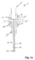
- a multi-region antenna 1 comprises a first antenna 3 with two dipole halves 3 'and 3 ", which are formed from an electrically conductive cylinder tube in the embodiment shown at its second end to the dipole half 3 'adjacent end 7' pot-shaped closed.
- a second dipole antenna For transmission of a second frequency range, in the illustrated embodiment of 1800 MHz, a second dipole antenna is provided, the dipole halves 9 'and 9 "according to the higher frequency range to be transmitted shorter in length dimensioned in the illustrated embodiment due to the twice as high transmission frequency only approx are half as long as the dipole halves 3 'and 3 ".
- dipole halves 9 'and 9 are also designed tubular or cylindrical in the embodiment shown, but with a larger diameter than the diameter of the dipole halves 3' and 3", so that the dipole halves of the antenna 9 with a shorter length inside the dipole halves 3 'and 3 "can absorb and overlap with greater longitudinal extent.
- the respective interleaved dipole halves 3' and 9 'or 3" and 9 are designed cup-shaped together and thereby to form a short circuit 11' and 11" electrically to each other connected.
- the drawing also shows that the lower dipole halves 3 "and 9" are fed via an outer conductor 15 of a coaxial feed line 17, the inner conductor 19 extending beyond the short circuit 11 "at the end 7" of the lower dipole half to the cup-shaped short-circuit connections 11 'of the upper dipole halves 3' and 9 'out and there is electrically and mechanically connected to the cup-shaped bottoms of these dipole halves 3' and 9 '.
- the mode of operation of the antenna is such that the dipole halves provided for the higher frequency band act as emitters in shorter longitudinal outward direction, but the inside of these cup-shaped dipole halves 9 'and 9 ", respectively, as a blocking pot larger longitudinal extension provided dipole halves of the second antenna can continue.
- the locking pot for the higher frequency of the outer tubular or cup-shaped dipole halves 9', 9" not "recognizable” or effective, so that these dipole halves outward look like single radiator.
- the inner side of the lower cup-shaped dipole half 3 acts as a blocking pot This locking pot effect ensures that no sheath waves can continue on the outer conductor of a coaxial feed line.
- the dipole halves need not necessarily be designed tubular or cup-shaped.
- angular (n-polygonal) or other dipole halves deviating from the circular shape for example oval-shaped designs circumferential outer surface is not necessarily closed, but is divided into several individual spatially curved or even planar elements, provided that at their adjacent inner end 7 'and 7 "of the dipole halves, where the above-mentioned pot-shaped short 11' and 11" formed is, electrically connected to each other and are designed so that the aforementioned barrier effect of the respective outer pot is maintained relative to the inner pot to ensure that no sheath waves can propagate.
- Dashed line is indicated in the embodiment shown in the accompanying figure that this design principle can be easily extended to other frequency bands. Dashed lines indicate that, for example, a further outer pot could be provided for dipole halves 25 'or 25 "of a third antenna 25, which is designed for an even higher frequency and therefore has an even shorter longitudinal extension 25 "are respectively shorted at their facing inner end with the end of the other dipole half.
- the outside of these dipole halves 25 'and 25 act for this frequency as a radiator, wherein the inside of the next inner dipole halves act as blocking pots. But these pots are again not effective for the nested inside dipole halves.
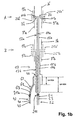
- a multi-region antenna according to FIG. 1b comprises a first antenna device A, which corresponds to the structure of the antenna device according to FIG. 1a.
- the reference symbols used in FIG. 1 a have only the letter extension "a" with respect to the antenna device A in FIG. 1b.
- the antenna device according to FIG. 1b also comprises a second multi-range antenna device B, which is constructed basically the same, wherein for this second antenna device B at the reference numerals the letter extension "b" deviates from "a" for the first multiple antenna device B.
- Area antenna device A is used.
- FIG. 2 shows a solution known from the prior art for a coaxial line 17 with an inner conductor 19 and an outer conductor 15, which has a coaxial stub line SL at a connection point 46, whose coaxial outer conductor AL is connected to the outer conductor 15 and the inner conductor IL is electrically connected to the inner conductor 19 of the coaxial line 17.
- the outer conductor AL is short-circuited to the associated inner conductor IL via a cup-shaped short-circuit KS, via which the inner conductor 19 is thus connected to the outer conductor 15 of the coaxial line 17.
- the antenna described in FIG. 1 is operated with only one frequency band with an upper and a lower antenna device, this can be realized via a common multiple coaxial line with a feed or decoupling device according to the invention shown in FIG.
- the exemplary embodiment according to FIG. 3 differs from FIG. 2, inter alia, in that at the connection point 46, the coaxial line 17 performs a right-angled bend, ie not coming down from above, as shown in FIG. 2, but is led away to the left at connection point 46 ,
- the spur line shown in Figure 2 is drawn in the embodiment of Figure 3 in the axial extension of the above the connection point 46 vertically upwardly extending coaxial connection line lying.
- Another difference is that the inner conductor 19 shown in FIG. 2 is replaced by a coaxial line 17a in FIG.
- an electrical connection to the inner conductor 19a or the outer conductor 15a of the inner coaxial line 17a for feeding the upper antenna device A can now be established, with a second feed line 42 an inner conductor 43 and an outer conductor 41 via a coaxial terminal 21b and a coaxial intermediate line 62 with an inner conductor 63 and an outer conductor 61, the outer coaxial line 17b is fed accordingly, including at the connection point 46 ultimately the inner conductor 63 of the second connecting line 42 with the inner conductor 19b and the outer conductor 41 is electrically connected to the outer conductor 15b of the feed line 17b.
- the intermediate line 62 thus represents the outer coaxial feed line 17b with the inner conductor 19b and the outer conductor 15b.
- a short-circuit KS1 or KS2 coaxial ⁇ / 4 lines are interleaved for reproduced in Figure 1 antenna device to operate, for example, two different frequency ranges, wherein the outer ⁇ 1/4 line SL1 (for adjustment with respect to the higher frequency SL2 (for adjustment with respect to the lower frequency, such as the 900 MHz range, for example, GSM) is used for example for the transmission of the 1800 MHz frequency range, for example, PCN) and the inner ⁇ 2/4-line.
- the inner outer conductor AL2 terminates freely adjacent to the connection point 46.
- the upper antenna device A is fed via a first coaxial cable connection 21a, wherein the inner conductor 53 merges into the inner conductor 19a and the outer conductor 51 of the connecting line 52 into the outer conductor 15a of the coaxial feed line 17a for the upper antenna device A.
- the feed of the lower antenna device B is such that the inner conductor 43 with the inner conductor 19b of the coaxial feed line 17 and the outer conductor 41 of the second coaxial cable connecting line to the outer conductor 15b of the triax line are electrically connected.
- the Einspeis- and coupling-out device is through the koaxialförmig interleaved and each short-circuited at its end stub lines SL1, SL2 carried out in function of the wavelength ⁇ 1/4 and ⁇ 2/4 relative to the two to be transmitted frequency ranges desired adjustment , wherein the first cup-shaped short-circuit line KS1 is approximately in the axial center with respect to the electrical length of the coaxial stub SL2 in adaptation to the frequency bands of 900 MHz and 1800 MHz to be transmitted in this embodiment.
- the design principle of the series connected short-circuit line KS1 and KS2 can also be realized in reverse order, namely, when the ⁇ 2/4 spur line SL2 outboard (to the outer conductor AL2) for the lower frequency and the ⁇ 1 / 4-stub cable SL1 (with outer conductor AL1) for the higher frequency (concentric) to the first stub line is arranged inside.
- the design effort for this is slightly higher.
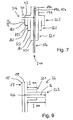
- FIG. 8 shows a further embodiment, modified with respect to FIG. 4, of a feeding or decoupling device, in which, for example, in addition to the exemplary embodiment according to FIG. 1, three superimposed antenna devices can be fed together via a multiple coaxial cable line 17, which in two frequency ranges work.
- a corresponding adaptation between an outer outer conductor and an associated inner conductor is shown in cascaded manner via two feed and coupling devices explained with reference to FIG. 4, which simultaneously represents the outer conductor for a next inner inner conductor.
- an outer conductor with its associated inner conductor is set to a common potential via the feed or coupling device 101 or 103 according to the invention.
- the embodiment according to FIG. 8 shows how This method can be expanded in several stages with other outer conductors AL1, AL2 and shorts KS3, KS4.
- a feed and decoupling device for a simple coaxial line 17 is shown with reference to FIG. 9, which, however, is provided with a broadband lightning protection, in the exemplary embodiment shown for two frequency band ranges.
- the function corresponds to the exemplary embodiment according to FIG. 4, except that instead of the inner coaxial conductor 17a shown in FIG. 4, only a simple inner conductor 15 is provided, so that this inner conductor runs without curvature in the axial direction and the two interleaved and again at the end Shorted stub line SL1 and SL2 branch off at right angles from this coaxial line 17.
- a simple inner conductor 15 is provided, so that this inner conductor runs without curvature in the axial direction and the two interleaved and again at the end Shorted stub line SL1 and SL2 branch off at right angles from this coaxial line 17.
Landscapes
- Physics & Mathematics (AREA)
- Electromagnetism (AREA)
- Variable-Direction Aerials And Aerial Arrays (AREA)
- Details Of Aerials (AREA)
- Waveguide Aerials (AREA)
- Aerials With Secondary Devices (AREA)
Applications Claiming Priority (5)
| Application Number | Priority Date | Filing Date | Title |
|---|---|---|---|
| DE19920980A DE19920980C2 (de) | 1999-05-06 | 1999-05-06 | Speise- oder Auskoppelvorrichtung für eine Koaxialleitung, insbesondere für eine Mehrfach-Koaxialleitung |
| DE19920978 | 1999-05-06 | ||
| DE19920980 | 1999-05-06 | ||
| DE19920978 | 1999-05-06 | ||
| PCT/EP2000/003999 WO2000069018A1 (de) | 1999-05-06 | 2000-05-04 | Mehr-bereichs-antenne |
Publications (2)
| Publication Number | Publication Date |
|---|---|
| EP1095426A1 EP1095426A1 (de) | 2001-05-02 |
| EP1095426B1 true EP1095426B1 (de) | 2007-12-19 |
Family
ID=26053260
Family Applications (1)
| Application Number | Title | Priority Date | Filing Date |
|---|---|---|---|
| EP00931113A Expired - Lifetime EP1095426B1 (de) | 1999-05-06 | 2000-05-04 | Mehr-bereichs-antenne |
Country Status (13)
| Country | Link |
|---|---|
| US (1) | US6421024B1 (enExample) |
| EP (1) | EP1095426B1 (enExample) |
| JP (1) | JP2002544692A (enExample) |
| KR (1) | KR100610995B1 (enExample) |
| CN (1) | CN1171353C (enExample) |
| AT (1) | ATE381794T1 (enExample) |
| AU (1) | AU762334B2 (enExample) |
| BR (1) | BR0006101A (enExample) |
| CA (1) | CA2336613C (enExample) |
| DE (1) | DE50014859D1 (enExample) |
| ES (1) | ES2296620T3 (enExample) |
| NZ (1) | NZ508835A (enExample) |
| WO (1) | WO2000069018A1 (enExample) |
Families Citing this family (28)
| Publication number | Priority date | Publication date | Assignee | Title |
|---|---|---|---|---|
| ES2241378T3 (es) | 1999-09-20 | 2005-10-16 | Fractus, S.A. | Antenas multinivel. |
| US6552692B1 (en) * | 2001-10-30 | 2003-04-22 | Andrew Corporation | Dual band sleeve dipole antenna |
| BR0307255A (pt) * | 2002-01-31 | 2004-12-14 | Galtronics Ltd | Antena dipolo de tubo ou manga coaxial de multi-bandas |
| CN100369322C (zh) * | 2003-02-09 | 2008-02-13 | 垠旺精密股份有限公司 | 平面式多频段全向性辐射场型天线 |
| TWI251957B (en) * | 2004-03-26 | 2006-03-21 | Hon Hai Prec Ind Co Ltd | Dual-band dipole antenna |
| CN2766358Y (zh) * | 2004-04-29 | 2006-03-22 | 富士康(昆山)电脑接插件有限公司 | 双频偶极天线 |
| EP1784894A1 (en) * | 2004-08-31 | 2007-05-16 | Fractus, S.A. | Slim multi-band antenna array for cellular base stations |
| TWI241745B (en) * | 2004-12-24 | 2005-10-11 | Advanced Connectek Inc | Ultra-wideband dipole antenna |
| JP4308786B2 (ja) * | 2005-02-24 | 2009-08-05 | パナソニック株式会社 | 携帯無線機 |
| ATE544194T1 (de) * | 2005-10-14 | 2012-02-15 | Fractus Sa | Schlankes dreifachband-antennenarray für zellulare basisstationen |
| US20070139289A1 (en) * | 2005-12-20 | 2007-06-21 | Arcadyan Technology Corporation | Dipole antenna |
| KR100688283B1 (ko) * | 2006-01-17 | 2007-03-02 | (주)에이스안테나 | 무선 통신 안테나 |
| US7327325B2 (en) * | 2006-04-14 | 2008-02-05 | Spx Corporation | Vertically polarized traveling wave antenna apparatus and method |
| US7586453B2 (en) * | 2006-12-19 | 2009-09-08 | Bae Systems Information And Electronic Systems Integration Inc. | Vehicular multiband antenna |
| JP5048012B2 (ja) * | 2008-05-12 | 2012-10-17 | 日本アンテナ株式会社 | コーリニアアンテナ |
| US20110287731A1 (en) * | 2009-02-02 | 2011-11-24 | Kazutoshi Hase | Antenna and reception apparatus provided with antenna |
| KR101038655B1 (ko) * | 2010-02-10 | 2011-06-02 | 주식회사 모비텍 | 커플링을 이용하여 동작주파수대역의 광대역 변환이 가능한 다중대역 로드 안테나 |
| CN101908669A (zh) * | 2010-06-30 | 2010-12-08 | 苏州市吴通天线有限公司 | 四分支多频柱状偶极子天线 |
| CN102447160A (zh) * | 2010-10-10 | 2012-05-09 | 四川九洲电器集团有限责任公司 | 新型宽带全向阵列天线辐射单元 |
| US8593363B2 (en) | 2011-01-27 | 2013-11-26 | Tdk Corporation | End-fed sleeve dipole antenna comprising a ¾-wave transformer |
| US8497808B2 (en) * | 2011-04-08 | 2013-07-30 | Wang Electro-Opto Corporation | Ultra-wideband miniaturized omnidirectional antennas via multi-mode three-dimensional (3-D) traveling-wave (TW) |
| CN103545609B (zh) * | 2013-11-06 | 2016-03-02 | 中国计量学院 | 树形分支结构三频段天线 |
| US9778368B2 (en) | 2014-09-07 | 2017-10-03 | Trimble Inc. | Satellite navigation using side by side antennas |
| CN109962341A (zh) * | 2017-12-22 | 2019-07-02 | 网件公司 | 天线结构及相关的构建及使用方法 |
| CN108183322B (zh) * | 2017-12-28 | 2024-02-06 | 东莞市仁丰电子科技有限公司 | 一种多波段三合一天线 |
| US11024982B2 (en) * | 2019-03-21 | 2021-06-01 | Samsung Electro-Mechanics Co., Ltd. | Antenna apparatus |
| US11469502B2 (en) * | 2019-06-25 | 2022-10-11 | Viavi Solutions Inc. | Ultra-wideband mobile mount antenna apparatus having a capacitive ground structure-based matching structure |
| US12327926B2 (en) * | 2023-01-12 | 2025-06-10 | Netgear, Inc. | Wi-Fi antennas using dielectric inserts with feedline tunnels for reduced electromagnetic interference (EMI) |
Family Cites Families (10)
| Publication number | Priority date | Publication date | Assignee | Title |
|---|---|---|---|---|
| US3022507A (en) | 1953-10-29 | 1962-02-20 | Antenna Engineering Lab | Multi-frequency antenna |
| SE402187B (sv) * | 1975-12-18 | 1978-06-19 | Philips Svenska Ab | Bredbandig dipolantenn |
| JPS55123203A (en) | 1979-03-16 | 1980-09-22 | Yoshiyuki Kino | Antenna |
| JPH0736488B2 (ja) | 1987-01-14 | 1995-04-19 | 松下電工株式会社 | 位相差給電形アンテナ |
| US4963879A (en) | 1989-07-31 | 1990-10-16 | Alliance Telecommunications Corp. | Double skirt omnidirectional dipole antenna |
| US5248988A (en) * | 1989-12-12 | 1993-09-28 | Nippon Antenna Co., Ltd. | Antenna used for a plurality of frequencies in common |
| US5440317A (en) * | 1993-05-17 | 1995-08-08 | At&T Corp. | Antenna assembly for a portable transceiver |
| US5521608A (en) * | 1994-02-24 | 1996-05-28 | Rockwell International | Multibay coplanar direction finding antenna |
| US5604506A (en) * | 1994-12-13 | 1997-02-18 | Trimble Navigation Limited | Dual frequency vertical antenna |
| KR19990001739A (ko) * | 1997-06-17 | 1999-01-15 | 윤종용 | 이동통신용 듀얼밴드 안테나 |
-
2000
- 2000-05-04 BR BR0006101-8A patent/BR0006101A/pt not_active IP Right Cessation
- 2000-05-04 CN CNB008007780A patent/CN1171353C/zh not_active Expired - Fee Related
- 2000-05-04 EP EP00931113A patent/EP1095426B1/de not_active Expired - Lifetime
- 2000-05-04 AU AU49166/00A patent/AU762334B2/en not_active Ceased
- 2000-05-04 NZ NZ508835A patent/NZ508835A/xx not_active IP Right Cessation
- 2000-05-04 ES ES00931113T patent/ES2296620T3/es not_active Expired - Lifetime
- 2000-05-04 AT AT00931113T patent/ATE381794T1/de not_active IP Right Cessation
- 2000-05-04 DE DE50014859T patent/DE50014859D1/de not_active Expired - Lifetime
- 2000-05-04 CA CA002336613A patent/CA2336613C/en not_active Expired - Fee Related
- 2000-05-04 KR KR1020007014524A patent/KR100610995B1/ko not_active Expired - Fee Related
- 2000-05-04 WO PCT/EP2000/003999 patent/WO2000069018A1/de not_active Ceased
- 2000-05-04 JP JP2000617517A patent/JP2002544692A/ja active Pending
- 2000-05-04 US US09/743,092 patent/US6421024B1/en not_active Expired - Lifetime
Also Published As
| Publication number | Publication date |
|---|---|
| AU4916600A (en) | 2000-11-21 |
| CN1304564A (zh) | 2001-07-18 |
| BR0006101A (pt) | 2001-04-03 |
| WO2000069018A1 (de) | 2000-11-16 |
| EP1095426A1 (de) | 2001-05-02 |
| ES2296620T3 (es) | 2008-05-01 |
| CA2336613A1 (en) | 2000-11-16 |
| NZ508835A (en) | 2002-11-26 |
| US6421024B1 (en) | 2002-07-16 |
| AU762334B2 (en) | 2003-06-26 |
| CA2336613C (en) | 2008-02-19 |
| ATE381794T1 (de) | 2008-01-15 |
| KR20010053060A (ko) | 2001-06-25 |
| KR100610995B1 (ko) | 2006-08-10 |
| JP2002544692A (ja) | 2002-12-24 |
| CN1171353C (zh) | 2004-10-13 |
| DE50014859D1 (de) | 2008-01-31 |
| HK1039217A1 (en) | 2002-04-12 |
Similar Documents
| Publication | Publication Date | Title |
|---|---|---|
| EP1095426B1 (de) | Mehr-bereichs-antenne | |
| DE60121470T2 (de) | Antennenanordnung | |
| DE60034042T2 (de) | Rahmenantenne mit vier resonanzfrequenzen | |
| EP3025395B1 (de) | Breitband-antennenarray | |
| DE10150150B4 (de) | Dualpolarisiertes Antennenarray | |
| DE102007047741B4 (de) | Mobilfunk-Gruppenantenne | |
| DE69832696T2 (de) | Phasenverzögerungsleitung für kollineare Gruppenantenne | |
| EP2929589B1 (de) | Dualpolarisierte, omnidirektionale antenne | |
| DE3433068C2 (enExample) | ||
| DE10150149A1 (de) | Antennenmodul | |
| EP1078424B1 (de) | Mehr-bereichs-antenne | |
| DE69839036T2 (de) | Zirkular polarisierte weitwinkel-antenne | |
| WO2003065505A1 (de) | Dualpolarisierte strahleranordnung | |
| EP1208614A1 (de) | Hochfrequenz-phasenschieberbaugruppe | |
| EP1239543A1 (de) | Flachantenne für die mobile Satellitenkommunikation | |
| EP3082193B1 (de) | Differenz-phasenschieberbaugruppe | |
| DE3709163A1 (de) | Niedrigprofil-breitband-monopolantenne | |
| DE3826777A1 (de) | Axiale zweibereichsantenne | |
| EP1525642A1 (de) | Zweidimensionales antennen-array | |
| DE102015007503A1 (de) | Dipolförmige Strahleranordnung | |
| EP1095421B1 (de) | Speise- oder auskoppelvorrichtung für koaxialleitung, insbesondere für mehrfach- koaxialleitung | |
| WO2004102742A1 (de) | Mehrbandfähige antenne | |
| DE10235222A1 (de) | Breitband-Antenne | |
| DE10239874B3 (de) | Antennensystem für mehrere Frequenzbereiche | |
| EP1056155A2 (de) | Mobilantenne, insbesondere Fahrzeugantenne, für zumindest eine zirkulare und zumindest eine lineare, vorzugsweise vertikale Polarisation |
Legal Events
| Date | Code | Title | Description |
|---|---|---|---|
| PUAI | Public reference made under article 153(3) epc to a published international application that has entered the european phase |
Free format text: ORIGINAL CODE: 0009012 |
|
| 17P | Request for examination filed |
Effective date: 20001207 |
|
| AK | Designated contracting states |
Kind code of ref document: A1 Designated state(s): AT BE CH CY DE DK ES FI FR GB GR IE IT LI LU MC NL PT SE |
|
| AX | Request for extension of the european patent |
Free format text: AL;LT;LV;MK;RO;SI |
|
| 17Q | First examination report despatched |
Effective date: 20061117 |
|
| GRAP | Despatch of communication of intention to grant a patent |
Free format text: ORIGINAL CODE: EPIDOSNIGR1 |
|
| GRAS | Grant fee paid |
Free format text: ORIGINAL CODE: EPIDOSNIGR3 |
|
| GRAA | (expected) grant |
Free format text: ORIGINAL CODE: 0009210 |
|
| AK | Designated contracting states |
Kind code of ref document: B1 Designated state(s): AT BE CH CY DE DK ES FI FR GB GR IE IT LI LU MC NL PT SE |
|
| REG | Reference to a national code |
Ref country code: GB Ref legal event code: FG4D Free format text: NOT ENGLISH |
|
| REG | Reference to a national code |
Ref country code: IE Ref legal event code: FG4D Free format text: LANGUAGE OF EP DOCUMENT: GERMAN |
|
| REG | Reference to a national code |
Ref country code: CH Ref legal event code: EP |
|
| REF | Corresponds to: |
Ref document number: 50014859 Country of ref document: DE Date of ref document: 20080131 Kind code of ref document: P |
|
| PG25 | Lapsed in a contracting state [announced via postgrant information from national office to epo] |
Ref country code: SE Free format text: LAPSE BECAUSE OF FAILURE TO SUBMIT A TRANSLATION OF THE DESCRIPTION OR TO PAY THE FEE WITHIN THE PRESCRIBED TIME-LIMIT Effective date: 20080319 |
|
| REG | Reference to a national code |
Ref country code: ES Ref legal event code: FG2A Ref document number: 2296620 Country of ref document: ES Kind code of ref document: T3 |
|
| PG25 | Lapsed in a contracting state [announced via postgrant information from national office to epo] |
Ref country code: FI Free format text: LAPSE BECAUSE OF FAILURE TO SUBMIT A TRANSLATION OF THE DESCRIPTION OR TO PAY THE FEE WITHIN THE PRESCRIBED TIME-LIMIT Effective date: 20071219 Ref country code: NL Free format text: LAPSE BECAUSE OF FAILURE TO SUBMIT A TRANSLATION OF THE DESCRIPTION OR TO PAY THE FEE WITHIN THE PRESCRIBED TIME-LIMIT Effective date: 20071219 |
|
| NLV1 | Nl: lapsed or annulled due to failure to fulfill the requirements of art. 29p and 29m of the patents act | ||
| GBV | Gb: ep patent (uk) treated as always having been void in accordance with gb section 77(7)/1977 [no translation filed] | ||
| ET | Fr: translation filed | ||
| PG25 | Lapsed in a contracting state [announced via postgrant information from national office to epo] |
Ref country code: PT Free format text: LAPSE BECAUSE OF FAILURE TO SUBMIT A TRANSLATION OF THE DESCRIPTION OR TO PAY THE FEE WITHIN THE PRESCRIBED TIME-LIMIT Effective date: 20080519 |
|
| REG | Reference to a national code |
Ref country code: IE Ref legal event code: FD4D |
|
| PLBE | No opposition filed within time limit |
Free format text: ORIGINAL CODE: 0009261 |
|
| STAA | Information on the status of an ep patent application or granted ep patent |
Free format text: STATUS: NO OPPOSITION FILED WITHIN TIME LIMIT |
|
| PG25 | Lapsed in a contracting state [announced via postgrant information from national office to epo] |
Ref country code: IE Free format text: LAPSE BECAUSE OF FAILURE TO SUBMIT A TRANSLATION OF THE DESCRIPTION OR TO PAY THE FEE WITHIN THE PRESCRIBED TIME-LIMIT Effective date: 20071219 Ref country code: DK Free format text: LAPSE BECAUSE OF FAILURE TO SUBMIT A TRANSLATION OF THE DESCRIPTION OR TO PAY THE FEE WITHIN THE PRESCRIBED TIME-LIMIT Effective date: 20071219 |
|
| 26N | No opposition filed |
Effective date: 20080922 |
|
| PG25 | Lapsed in a contracting state [announced via postgrant information from national office to epo] |
Ref country code: GB Free format text: LAPSE BECAUSE OF FAILURE TO SUBMIT A TRANSLATION OF THE DESCRIPTION OR TO PAY THE FEE WITHIN THE PRESCRIBED TIME-LIMIT Effective date: 20071219 |
|
| BERE | Be: lapsed |
Owner name: KATHREIN-WERKE K.G. Effective date: 20080531 |
|
| PG25 | Lapsed in a contracting state [announced via postgrant information from national office to epo] |
Ref country code: MC Free format text: LAPSE BECAUSE OF NON-PAYMENT OF DUE FEES Effective date: 20080531 |
|
| REG | Reference to a national code |
Ref country code: CH Ref legal event code: PL |
|
| PG25 | Lapsed in a contracting state [announced via postgrant information from national office to epo] |
Ref country code: CH Free format text: LAPSE BECAUSE OF NON-PAYMENT OF DUE FEES Effective date: 20080531 Ref country code: LI Free format text: LAPSE BECAUSE OF NON-PAYMENT OF DUE FEES Effective date: 20080531 Ref country code: GR Free format text: LAPSE BECAUSE OF FAILURE TO SUBMIT A TRANSLATION OF THE DESCRIPTION OR TO PAY THE FEE WITHIN THE PRESCRIBED TIME-LIMIT Effective date: 20080320 |
|
| PG25 | Lapsed in a contracting state [announced via postgrant information from national office to epo] |
Ref country code: BE Free format text: LAPSE BECAUSE OF NON-PAYMENT OF DUE FEES Effective date: 20080531 |
|
| PG25 | Lapsed in a contracting state [announced via postgrant information from national office to epo] |
Ref country code: CY Free format text: LAPSE BECAUSE OF FAILURE TO SUBMIT A TRANSLATION OF THE DESCRIPTION OR TO PAY THE FEE WITHIN THE PRESCRIBED TIME-LIMIT Effective date: 20071219 |
|
| PG25 | Lapsed in a contracting state [announced via postgrant information from national office to epo] |
Ref country code: AT Free format text: LAPSE BECAUSE OF NON-PAYMENT OF DUE FEES Effective date: 20080504 |
|
| PG25 | Lapsed in a contracting state [announced via postgrant information from national office to epo] |
Ref country code: LU Free format text: LAPSE BECAUSE OF NON-PAYMENT OF DUE FEES Effective date: 20080504 |
|
| PG25 | Lapsed in a contracting state [announced via postgrant information from national office to epo] |
Ref country code: IT Free format text: LAPSE BECAUSE OF NON-PAYMENT OF DUE FEES Effective date: 20080531 |
|
| REG | Reference to a national code |
Ref country code: FR Ref legal event code: PLFP Year of fee payment: 17 |
|
| PGFP | Annual fee paid to national office [announced via postgrant information from national office to epo] |
Ref country code: ES Payment date: 20160523 Year of fee payment: 17 |
|
| PGFP | Annual fee paid to national office [announced via postgrant information from national office to epo] |
Ref country code: FR Payment date: 20160523 Year of fee payment: 17 |
|
| REG | Reference to a national code |
Ref country code: FR Ref legal event code: ST Effective date: 20180131 |
|
| PG25 | Lapsed in a contracting state [announced via postgrant information from national office to epo] |
Ref country code: FR Free format text: LAPSE BECAUSE OF NON-PAYMENT OF DUE FEES Effective date: 20170531 |
|
| REG | Reference to a national code |
Ref country code: ES Ref legal event code: FD2A Effective date: 20180628 |
|
| REG | Reference to a national code |
Ref country code: DE Ref legal event code: R082 Ref document number: 50014859 Country of ref document: DE Representative=s name: FLACH BAUER STAHL PATENTANWAELTE PARTNERSCHAFT, DE |
|
| PG25 | Lapsed in a contracting state [announced via postgrant information from national office to epo] |
Ref country code: ES Free format text: LAPSE BECAUSE OF NON-PAYMENT OF DUE FEES Effective date: 20170505 |
|
| REG | Reference to a national code |
Ref country code: DE Ref legal event code: R081 Ref document number: 50014859 Country of ref document: DE Owner name: ERICSSON AB, SE Free format text: FORMER OWNER: KATHREIN-WERKE KG, 83022 ROSENHEIM, DE Ref country code: DE Ref legal event code: R081 Ref document number: 50014859 Country of ref document: DE Owner name: TELEFONAKTIEBOLAGET LM ERICSSON (PUBL), SE Free format text: FORMER OWNER: KATHREIN-WERKE KG, 83022 ROSENHEIM, DE Ref country code: DE Ref legal event code: R082 Ref document number: 50014859 Country of ref document: DE Representative=s name: FLACH BAUER STAHL PATENTANWAELTE PARTNERSCHAFT, DE Ref country code: DE Ref legal event code: R081 Ref document number: 50014859 Country of ref document: DE Owner name: KATHREIN SE, DE Free format text: FORMER OWNER: KATHREIN-WERKE KG, 83022 ROSENHEIM, DE |
|
| PGFP | Annual fee paid to national office [announced via postgrant information from national office to epo] |
Ref country code: DE Payment date: 20190522 Year of fee payment: 20 |
|
| REG | Reference to a national code |
Ref country code: DE Ref legal event code: R081 Ref document number: 50014859 Country of ref document: DE Owner name: ERICSSON AB, SE Free format text: FORMER OWNER: KATHREIN SE, 83022 ROSENHEIM, DE Ref country code: DE Ref legal event code: R082 Ref document number: 50014859 Country of ref document: DE Representative=s name: FLACH BAUER STAHL PATENTANWAELTE PARTNERSCHAFT, DE Ref country code: DE Ref legal event code: R081 Ref document number: 50014859 Country of ref document: DE Owner name: TELEFONAKTIEBOLAGET LM ERICSSON (PUBL), SE Free format text: FORMER OWNER: KATHREIN SE, 83022 ROSENHEIM, DE |
|
| REG | Reference to a national code |
Ref country code: DE Ref legal event code: R071 Ref document number: 50014859 Country of ref document: DE |
|
| REG | Reference to a national code |
Ref country code: DE Ref legal event code: R082 Ref document number: 50014859 Country of ref document: DE Representative=s name: FLACH BAUER STAHL PATENTANWAELTE PARTNERSCHAFT, DE Ref country code: DE Ref legal event code: R081 Ref document number: 50014859 Country of ref document: DE Owner name: TELEFONAKTIEBOLAGET LM ERICSSON (PUBL), SE Free format text: FORMER OWNER: ERICSSON AB, STOCKHOLM, SE |