EP1095426B1 - Multi-frequency band antenna - Google Patents
Multi-frequency band antenna Download PDFInfo
- Publication number
- EP1095426B1 EP1095426B1 EP00931113A EP00931113A EP1095426B1 EP 1095426 B1 EP1095426 B1 EP 1095426B1 EP 00931113 A EP00931113 A EP 00931113A EP 00931113 A EP00931113 A EP 00931113A EP 1095426 B1 EP1095426 B1 EP 1095426B1
- Authority
- EP
- European Patent Office
- Prior art keywords
- coaxial
- line
- antenna
- conductor
- dipole halves
- Prior art date
- Legal status (The legal status is an assumption and is not a legal conclusion. Google has not performed a legal analysis and makes no representation as to the accuracy of the status listed.)
- Expired - Lifetime
Links
Images


Classifications
-
- H—ELECTRICITY
- H01—ELECTRIC ELEMENTS
- H01Q—ANTENNAS, i.e. RADIO AERIALS
- H01Q5/00—Arrangements for simultaneous operation of antennas on two or more different wavebands, e.g. dual-band or multi-band arrangements
-
- H—ELECTRICITY
- H01—ELECTRIC ELEMENTS
- H01Q—ANTENNAS, i.e. RADIO AERIALS
- H01Q21/00—Antenna arrays or systems
- H01Q21/30—Combinations of separate antenna units operating in different wavebands and connected to a common feeder system
-
- H—ELECTRICITY
- H01—ELECTRIC ELEMENTS
- H01P—WAVEGUIDES; RESONATORS, LINES, OR OTHER DEVICES OF THE WAVEGUIDE TYPE
- H01P5/00—Coupling devices of the waveguide type
- H01P5/12—Coupling devices having more than two ports
- H01P5/16—Conjugate devices, i.e. devices having at least one port decoupled from one other port
-
- H—ELECTRICITY
- H01—ELECTRIC ELEMENTS
- H01Q—ANTENNAS, i.e. RADIO AERIALS
- H01Q5/00—Arrangements for simultaneous operation of antennas on two or more different wavebands, e.g. dual-band or multi-band arrangements
- H01Q5/20—Arrangements for simultaneous operation of antennas on two or more different wavebands, e.g. dual-band or multi-band arrangements characterised by the operating wavebands
- H01Q5/25—Ultra-wideband [UWB] systems, e.g. multiple resonance systems; Pulse systems
-
- H—ELECTRICITY
- H01—ELECTRIC ELEMENTS
- H01Q—ANTENNAS, i.e. RADIO AERIALS
- H01Q5/00—Arrangements for simultaneous operation of antennas on two or more different wavebands, e.g. dual-band or multi-band arrangements
- H01Q5/30—Arrangements for providing operation on different wavebands
- H01Q5/307—Individual or coupled radiating elements, each element being fed in an unspecified way
- H01Q5/342—Individual or coupled radiating elements, each element being fed in an unspecified way for different propagation modes
- H01Q5/357—Individual or coupled radiating elements, each element being fed in an unspecified way for different propagation modes using a single feed point
- H01Q5/364—Creating multiple current paths
- H01Q5/371—Branching current paths
-
- H—ELECTRICITY
- H01—ELECTRIC ELEMENTS
- H01Q—ANTENNAS, i.e. RADIO AERIALS
- H01Q5/00—Arrangements for simultaneous operation of antennas on two or more different wavebands, e.g. dual-band or multi-band arrangements
- H01Q5/40—Imbricated or interleaved structures; Combined or electromagnetically coupled arrangements, e.g. comprising two or more non-connected fed radiating elements
- H01Q5/48—Combinations of two or more dipole type antennas
-
- H—ELECTRICITY
- H01—ELECTRIC ELEMENTS
- H01Q—ANTENNAS, i.e. RADIO AERIALS
- H01Q9/00—Electrically-short antennas having dimensions not more than twice the operating wavelength and consisting of conductive active radiating elements
- H01Q9/04—Resonant antennas
- H01Q9/16—Resonant antennas with feed intermediate between the extremities of the antenna, e.g. centre-fed dipole
- H01Q9/28—Conical, cylindrical, cage, strip, gauze, or like elements having an extended radiating surface; Elements comprising two conical surfaces having collinear axes and adjacent apices and fed by two-conductor transmission lines
- H01Q9/285—Planar dipole
-
- H—ELECTRICITY
- H01—ELECTRIC ELEMENTS
- H01Q—ANTENNAS, i.e. RADIO AERIALS
- H01Q9/00—Electrically-short antennas having dimensions not more than twice the operating wavelength and consisting of conductive active radiating elements
- H01Q9/04—Resonant antennas
- H01Q9/30—Resonant antennas with feed to end of elongated active element, e.g. unipole
- H01Q9/32—Vertical arrangement of element
Definitions
- the invention relates to a multi-range antenna according to the preamble of claim 1.
- GSM 900 Global System for Mobile Communications
- GSM 1800 GSM 1800 standard, in which signals can be received and transmitted in a 1800 MHz range.
- multi-span antenna devices are required for transmitting and receiving various frequency ranges, which typically include dipole structures, ie a dipole antenna device for transmitting and receiving the 900 MHz band and another dipole antenna device for transmitting and receiving the 1800 MHz -Band Schemees.
- more or at least two-range antenna devices have been proposed, namely for example a dipole antenna device for transmitting the 900 MHz range and for transmitting the 1800 MHz range, with both dipole antenna devices being arranged side by side.
- two antennas are required for the at least two frequency ranges, but because of the spatial arrangement next to each other, they hinder each other and impair each other, as they shade each other in the radiation field. As a result, no round jet diagram can be achieved anymore.
- a generic antenna arrangement is known from U.S.-A-4,125,840 known.
- This prior publication describes a broadband dipole antenna with multiple dipoles comprising dipole halves of different lengths.
- the one dipole halves are positioned on the side facing away from the feed line arrangement, whereas the other part of the dipole halves are arranged on the side facing the feed line arrangement.
- the dipole halves consist of a number of thin ones electrical conductors, which are arranged on a cylindrical or conical surface of a cylindrical plastic tube.
- Each multiple dipole halves belong to a group and have substantially the same physical length.
- the conductors belonging to different groups have substantially different lengths, whereby the antenna can transmit and / or receive at different frequencies.
- the dipole halves are in each case fed at their mutually facing inner sides, namely the dipole halves projecting away from the feed line arrangement via an inner conductor and the dipole halves facing the feed line arrangement via the outer conductor of a coaxial feed line arrangement.
- a coplanar multiband antenna comprising a plurality of circumferentially spaced mast array dipoles in a vertical orientation. Offset in the longitudinal direction of the mast are arranged dipoles of different lengths, which radiate in different frequency bands.
- an object of the present invention is an improved dual or multi-range antenna device to accomplish.
- the present invention in a startling manner, provides a completely new, highly compact antenna device that can be operated in two frequency bands as compared to the prior art. If required, this antenna device can also be expanded to a multi-band antenna comprising more than two frequency bands.
- the dipole antenna device for the first frequency band and the dipole device for the at least one further frequency band offset thereto are formed coaxially with one another and interleaved with one another.
- the dipole halves are preferably cup-shaped, wherein the pot diameter of the dipole halves differs from each other so far that the pots are arranged one inside the other.
- the length of the dipole halves depends on the frequency band to be transmitted.
- the cup-shaped dipole halves which are shorter in their length and are required for the higher frequency range, lie outside, the dipole halves correspondingly longer for the lower frequency range being arranged inside these outer pots and projecting beyond the outer dipole pots.
- the outer and inner pots of the dipole halves are electrically and mechanically connected at their inner sides to a cup bottom-like short circuit point, wherein the one half-cupped nested dipole halves are contacted with an inner conductor and the other nested dipole halves with the outer conductor.
- the cup-shaped dipole halves which are too far-reaching and suitable for the higher frequency range, act as dipole radiators towards the outside, but inwardly as blocking pots, so that the cup-shaped dipole halves provided for the low frequency range are not recognizable for these radiators ,
- each longer-sized and provided for the lower frequency band cup-shaped dipole acts outwardly in its entire length as a radiator, without the blocking effect of the outer pot-shaped radiator for the higher frequency range would be effective, inwardly as a blocking pot, so that no sheath waves the outer conductor can run away.
- each of the pots with higher frequency in their shorter longitudinal extent have larger diameter and record the cup-shaped dipole halves for the lower frequency range in each case interleaved internally.
- This design principle also allows the Power supply is centrally via a common connection or a coaxial coaxial line, which preferably not only serves for feeding, but also equal to the mechanical stability and support of the antenna is used.
- the designed as outer conductor koaxialode standpipe is in the corresponding feed point, ie mechanically connected to the short circuit of a dipole half with this, the inner conductor led over a small amount beyond the outer conductor and there electrically and mechanically connected to the cup bottom-like short circuit of the other dipole halves is. With appropriate stiffness of the inner conductor no additional stability measures additional measures are necessary. Otherwise could be provided between the cup-shaped short-circuit locations of the adjacent dipole halves electrically non-effective, serving stability additional measures.
- the entire antenna shown in the accompanying figure is housed in a protective tube, such as a tube made of glass fiber reinforced plastic tube which fits over the antenna assembly as accurately as possible, so that the inner conductor hold the upper dipole halves only by weight and must accommodate, since tipping loads and Movements are absorbed by the protective tube.
- a protective tube such as a tube made of glass fiber reinforced plastic tube which fits over the antenna assembly as accurately as possible, so that the inner conductor hold the upper dipole halves only by weight and must accommodate, since tipping loads and Movements are absorbed by the protective tube.
- the feed can be effected via only a single coaxial cable connection.
- cup-like Constructions are formed.
- these cup-shaped design dipole halves can be designed circular or cylindrical and be provided with square or even oval cross-section. They also do not necessarily have to be designed as closed tubes. Also possible are multi-membered constructions in which the cup-like dipole halves consist of several individual conductor sections or electrically conductive elements or are divided into these, provided that they are short-circuited to each other at their respectively adjacent adjacent second dipole feed end.
- a multi-frequency band antenna device which preferably comprises at least two superimposed antenna devices, which in turn can radiate at least in two frequency bands as two frequency ranges.
- the feed line respectively serve the outer electrical conductors of the Mehrfachkoaxial feeders for feeding to the dipole halves of the lower-lying antenna device
- the opposite inner conductor of the coaxial line for example, the generally wire-shaped inner conductor and the surrounding innermost coaxial conductor
- the design principle can be cascaded accordingly, so that three antenna devices and more can be arranged one above the other.
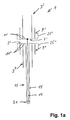
- a multi-region antenna 1 comprises a first antenna 3 with two dipole halves 3 'and 3 ", which are formed from an electrically conductive cylinder tube in the embodiment shown at its second end to the dipole half 3 'adjacent end 7' pot-shaped closed.
- a second dipole antenna For transmission of a second frequency range, in the illustrated embodiment of 1800 MHz, a second dipole antenna is provided, the dipole halves 9 'and 9 "according to the higher frequency range to be transmitted shorter in length dimensioned in the illustrated embodiment due to the twice as high transmission frequency only approx are half as long as the dipole halves 3 'and 3 ".
- dipole halves 9 'and 9 are also designed tubular or cylindrical in the embodiment shown, but with a larger diameter than the diameter of the dipole halves 3' and 3", so that the dipole halves of the antenna 9 with a shorter length inside the dipole halves 3 'and 3 "can absorb and overlap with greater longitudinal extent.
- the respective interleaved dipole halves 3' and 9 'or 3" and 9 are designed cup-shaped together and thereby to form a short circuit 11' and 11" electrically to each other connected.
- the drawing also shows that the lower dipole halves 3 "and 9" are fed via an outer conductor 15 of a coaxial feed line 17, the inner conductor 19 extending beyond the short circuit 11 "at the end 7" of the lower dipole half to the cup-shaped short-circuit connections 11 'of the upper dipole halves 3' and 9 'out and there is electrically and mechanically connected to the cup-shaped bottoms of these dipole halves 3' and 9 '.
- the mode of operation of the antenna is such that the dipole halves provided for the higher frequency band act as emitters in shorter longitudinal outward direction, but the inside of these cup-shaped dipole halves 9 'and 9 ", respectively, as a blocking pot larger longitudinal extension provided dipole halves of the second antenna can continue.
- the locking pot for the higher frequency of the outer tubular or cup-shaped dipole halves 9', 9" not "recognizable” or effective, so that these dipole halves outward look like single radiator.
- the inner side of the lower cup-shaped dipole half 3 acts as a blocking pot This locking pot effect ensures that no sheath waves can continue on the outer conductor of a coaxial feed line.
- the dipole halves need not necessarily be designed tubular or cup-shaped.
- angular (n-polygonal) or other dipole halves deviating from the circular shape for example oval-shaped designs circumferential outer surface is not necessarily closed, but is divided into several individual spatially curved or even planar elements, provided that at their adjacent inner end 7 'and 7 "of the dipole halves, where the above-mentioned pot-shaped short 11' and 11" formed is, electrically connected to each other and are designed so that the aforementioned barrier effect of the respective outer pot is maintained relative to the inner pot to ensure that no sheath waves can propagate.
- Dashed line is indicated in the embodiment shown in the accompanying figure that this design principle can be easily extended to other frequency bands. Dashed lines indicate that, for example, a further outer pot could be provided for dipole halves 25 'or 25 "of a third antenna 25, which is designed for an even higher frequency and therefore has an even shorter longitudinal extension 25 "are respectively shorted at their facing inner end with the end of the other dipole half.
- the outside of these dipole halves 25 'and 25 act for this frequency as a radiator, wherein the inside of the next inner dipole halves act as blocking pots. But these pots are again not effective for the nested inside dipole halves.
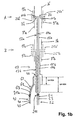
- a multi-region antenna according to FIG. 1b comprises a first antenna device A, which corresponds to the structure of the antenna device according to FIG. 1a.
- the reference symbols used in FIG. 1 a have only the letter extension "a" with respect to the antenna device A in FIG. 1b.
- the antenna device according to FIG. 1b also comprises a second multi-range antenna device B, which is constructed basically the same, wherein for this second antenna device B at the reference numerals the letter extension "b" deviates from "a" for the first multiple antenna device B.
- Area antenna device A is used.
- FIG. 2 shows a solution known from the prior art for a coaxial line 17 with an inner conductor 19 and an outer conductor 15, which has a coaxial stub line SL at a connection point 46, whose coaxial outer conductor AL is connected to the outer conductor 15 and the inner conductor IL is electrically connected to the inner conductor 19 of the coaxial line 17.
- the outer conductor AL is short-circuited to the associated inner conductor IL via a cup-shaped short-circuit KS, via which the inner conductor 19 is thus connected to the outer conductor 15 of the coaxial line 17.
- the antenna described in FIG. 1 is operated with only one frequency band with an upper and a lower antenna device, this can be realized via a common multiple coaxial line with a feed or decoupling device according to the invention shown in FIG.
- the exemplary embodiment according to FIG. 3 differs from FIG. 2, inter alia, in that at the connection point 46, the coaxial line 17 performs a right-angled bend, ie not coming down from above, as shown in FIG. 2, but is led away to the left at connection point 46 ,
- the spur line shown in Figure 2 is drawn in the embodiment of Figure 3 in the axial extension of the above the connection point 46 vertically upwardly extending coaxial connection line lying.
- Another difference is that the inner conductor 19 shown in FIG. 2 is replaced by a coaxial line 17a in FIG.
- an electrical connection to the inner conductor 19a or the outer conductor 15a of the inner coaxial line 17a for feeding the upper antenna device A can now be established, with a second feed line 42 an inner conductor 43 and an outer conductor 41 via a coaxial terminal 21b and a coaxial intermediate line 62 with an inner conductor 63 and an outer conductor 61, the outer coaxial line 17b is fed accordingly, including at the connection point 46 ultimately the inner conductor 63 of the second connecting line 42 with the inner conductor 19b and the outer conductor 41 is electrically connected to the outer conductor 15b of the feed line 17b.
- the intermediate line 62 thus represents the outer coaxial feed line 17b with the inner conductor 19b and the outer conductor 15b.
- a short-circuit KS1 or KS2 coaxial ⁇ / 4 lines are interleaved for reproduced in Figure 1 antenna device to operate, for example, two different frequency ranges, wherein the outer ⁇ 1/4 line SL1 (for adjustment with respect to the higher frequency SL2 (for adjustment with respect to the lower frequency, such as the 900 MHz range, for example, GSM) is used for example for the transmission of the 1800 MHz frequency range, for example, PCN) and the inner ⁇ 2/4-line.
- the inner outer conductor AL2 terminates freely adjacent to the connection point 46.
- the upper antenna device A is fed via a first coaxial cable connection 21a, wherein the inner conductor 53 merges into the inner conductor 19a and the outer conductor 51 of the connecting line 52 into the outer conductor 15a of the coaxial feed line 17a for the upper antenna device A.
- the feed of the lower antenna device B is such that the inner conductor 43 with the inner conductor 19b of the coaxial feed line 17 and the outer conductor 41 of the second coaxial cable connecting line to the outer conductor 15b of the triax line are electrically connected.
- the Einspeis- and coupling-out device is through the koaxialförmig interleaved and each short-circuited at its end stub lines SL1, SL2 carried out in function of the wavelength ⁇ 1/4 and ⁇ 2/4 relative to the two to be transmitted frequency ranges desired adjustment , wherein the first cup-shaped short-circuit line KS1 is approximately in the axial center with respect to the electrical length of the coaxial stub SL2 in adaptation to the frequency bands of 900 MHz and 1800 MHz to be transmitted in this embodiment.
- the design principle of the series connected short-circuit line KS1 and KS2 can also be realized in reverse order, namely, when the ⁇ 2/4 spur line SL2 outboard (to the outer conductor AL2) for the lower frequency and the ⁇ 1 / 4-stub cable SL1 (with outer conductor AL1) for the higher frequency (concentric) to the first stub line is arranged inside.
- the design effort for this is slightly higher.
- FIG. 8 shows a further embodiment, modified with respect to FIG. 4, of a feeding or decoupling device, in which, for example, in addition to the exemplary embodiment according to FIG. 1, three superimposed antenna devices can be fed together via a multiple coaxial cable line 17, which in two frequency ranges work.
- a corresponding adaptation between an outer outer conductor and an associated inner conductor is shown in cascaded manner via two feed and coupling devices explained with reference to FIG. 4, which simultaneously represents the outer conductor for a next inner inner conductor.
- an outer conductor with its associated inner conductor is set to a common potential via the feed or coupling device 101 or 103 according to the invention.
- the embodiment according to FIG. 8 shows how This method can be expanded in several stages with other outer conductors AL1, AL2 and shorts KS3, KS4.
- a feed and decoupling device for a simple coaxial line 17 is shown with reference to FIG. 9, which, however, is provided with a broadband lightning protection, in the exemplary embodiment shown for two frequency band ranges.
- the function corresponds to the exemplary embodiment according to FIG. 4, except that instead of the inner coaxial conductor 17a shown in FIG. 4, only a simple inner conductor 15 is provided, so that this inner conductor runs without curvature in the axial direction and the two interleaved and again at the end Shorted stub line SL1 and SL2 branch off at right angles from this coaxial line 17.
- a simple inner conductor 15 is provided, so that this inner conductor runs without curvature in the axial direction and the two interleaved and again at the end Shorted stub line SL1 and SL2 branch off at right angles from this coaxial line 17.
Abstract
Description
Die Erfindung betrifft eine Mehr-Bereichs-Antenne nach dem Oberbegriff des Anspruchs 1.The invention relates to a multi-range antenna according to the preamble of
Mobile Kommunikation wird größtenteils über das GSM 900-Netz, also im 900 MHz-Bereich abgewickelt. Daneben hat sich v.a. in Europa auch der GSM 1800-Standard etabliert, bei welchem in einem 1800 MHz-Bereich Signale empfangen und gesendet werden können.Mobile communication is largely handled via the GSM 900 network, ie in the 900 MHz range. In addition, v.a. In Europe also established the GSM 1800 standard, in which signals can be received and transmitted in a 1800 MHz range.
Für derartige Mehr-Bereichs-Basisstationen werden deshalb Mehr-Bereichs-Antenneneinrichtungen zum Senden und Empfangen verschiedener Frequenzbereiche benötigt, die üblicherweise Dipolstrukturen aufweisen, also eine Dipolantenneneinrichtung zum Senden und Empfangen des 900 MHz-Bandbereiches und eine weitere Dipolantenneneinrichtung zum Senden und Empfangen des 1800 MHz-Bandbereiches.For such multi-span base stations, therefore, multi-span antenna devices are required for transmitting and receiving various frequency ranges, which typically include dipole structures, ie a dipole antenna device for transmitting and receiving the 900 MHz band and another dipole antenna device for transmitting and receiving the 1800 MHz -Bandbereiches.
In der Praxis sind deshalb bereits Mehr- oder zumindest Zwei-Bereichs-Antenneneinrichtungen vorgeschlagen worden, nämlich beispielsweise eine Dipolantenneneinrichtung zur Übertragung des 900 MHz-Bereiches sowie zur Übertragung des 1800 MHz-Bereiches, wobei beide Dipolantenneneinrichtungen nebeneinander angeordnet sind. Man benötigt also auf jeden Fall für die zumindest beiden Frequenzbereiche zwei Antennen, die aufgrund der räumlichen Anordnung nebeneinander sich allerdings gegenseitig behindern und beeinträchtigen, da sie sich gegenseitig im Strahlungsfeld abschatten. Dadurch lässt sich kein Rundstrahldiagramm mehr erzielen.Therefore, in practice, more or at least two-range antenna devices have been proposed, namely for example a dipole antenna device for transmitting the 900 MHz range and for transmitting the 1800 MHz range, with both dipole antenna devices being arranged side by side. In any case, therefore, two antennas are required for the at least two frequency ranges, but because of the spatial arrangement next to each other, they hinder each other and impair each other, as they shade each other in the radiation field. As a result, no round jet diagram can be achieved anymore.
Es ist deshalb auch bereits vorgeschlagen worden, zwei entsprechende Antenneneinrichtungen zum Betrieb in zwei unterschiedlichen Frequenzbereichen oder-bändern übereinander anzuordnen. Dies führt natürlich zu einer größeren Bauhöhe und erfordert einen größeren Platzbedarf. Zudem wird das Rundstrahldiagramm unter Umständen auch zumindest geringfügig dadurch beeinträchtigt, dass die zu der höheren Antenneneinrichtung führende Anschlussleitung an der tieferliegenden Antenneneinrichtung vorbeigeführt werden muss.It has therefore already been proposed to arrange two corresponding antenna devices for operation in two different frequency ranges or bands on top of each other. Of course, this leads to a larger overall height and requires a larger space requirement. In addition, under certain circumstances, the omnidirectional diagram is also at least slightly impaired in that the connecting line leading to the higher antenna device must be guided past the lower-lying antenna device.
Eine gattungsbildende Antennenanordnung ist aus der
Aus der Veröffentlichung "
Schließlich ist auch noch aus der
Aufgabe der vorliegenden Erfindung ist es demgegenüber eine verbesserte Zwei- oder Mehr-Bereichs-Antenneneinrichtung zu schaffen.In contrast, an object of the present invention is an improved dual or multi-range antenna device to accomplish.
Diese Aufgabe wird erfindungsgemäß entsprechend den im Anspruch 1 angegebenen Merkmalen gelöst. Vorteilhafte Ausgestaltungen der Erfindung sind in den Unteransprüchen angegeben.This object is achieved according to the features specified in
Die vorliegende Erfindung schafft gegenüber dem Stand der Technik auf verblüffende Art und Weise eine völlig neuartige, höchst kompakte Antenneneinrichtung, die in zwei Frequenzbändern betrieben werden kann. Bei Bedarf ist diese Antenneneinrichtung auch zu einer mehr als zwei Frequenzbänder umfassenden Multi-Band-Antenne ausbaubar.The present invention, in a startling manner, provides a completely new, highly compact antenna device that can be operated in two frequency bands as compared to the prior art. If required, this antenna device can also be expanded to a multi-band antenna comprising more than two frequency bands.
Erfindungsgemäß ist nämlich vorgesehen, dass die DipolAntenneneinrichtung für das erste Frequenzband und die Dipoleinrichtung für das zumindest eine weitere dazu versetzt liegende Frequenzband koaxial zueinander und dabei ineinander verschachtelt liegend ausgebildet sind.In accordance with the invention, it is provided that the dipole antenna device for the first frequency band and the dipole device for the at least one further frequency band offset thereto are formed coaxially with one another and interleaved with one another.
Erfindungsgemäß sind dazu die Dipolhälften vorzugsweise topfförmig gestaltet, wobei der Topfdurchmesser der Dipolhälften insoweit voneinander abweicht, dass die Töpfe ineinander liegend angeordnet sind. Die Länge der Dipolhälften hängt dabei von dem zu übertragenden Frequenzband ab. Die in ihrer Länge kürzer dimensionierten und für den höheren Frequenzbereich benötigten topfförmigen Dipolhälften liegen dabei außen, wobei die für den niedrigeren Frequenzbereich entsprechend länger dimensionierten Dipolhälften in diesen äußeren Töpfen innenliegend angeordnet sind und die äußeren Dipoltöpfe in ihrer Länge überragen.According to the invention, the dipole halves are preferably cup-shaped, wherein the pot diameter of the dipole halves differs from each other so far that the pots are arranged one inside the other. The length of the dipole halves depends on the frequency band to be transmitted. The cup-shaped dipole halves, which are shorter in their length and are required for the higher frequency range, lie outside, the dipole halves correspondingly longer for the lower frequency range being arranged inside these outer pots and projecting beyond the outer dipole pots.
Die äußeren und inneren Töpfe der Dipolhälften sind an ihren innenliegenden Seiten jeweils mit einer topfbodenähnlichen Kurzschlussstelle elektrisch und mechanisch verbunden, wobei die einen ineinander topfförmig verschachtelten Dipolhälften mit einem Innenleiter und die anderen verschachtelt ineinander liegenden Dipolhälften mit dem Außenleiter kontaktiert sind.The outer and inner pots of the dipole halves are electrically and mechanically connected at their inner sides to a cup bottom-like short circuit point, wherein the one half-cupped nested dipole halves are contacted with an inner conductor and the other nested dipole halves with the outer conductor.
Die Besonderheit dieses Konstruktionsprinzips liegt darin, dass beispielsweise die zu äußerst liegenden und für den höheren Frequenzbereich geeigneten topfförmigen Dipolhälften nach außen hin als Dipolstrahler wirken, nach innen jedoch als Sperrtopf, so dass für diese Strahler die für den niedrigen Frequenzbereich vorgesehenen topfförmigen Dipolhälften nicht erkennbar sind.The peculiarity of this design principle is that, for example, the cup-shaped dipole halves, which are too far-reaching and suitable for the higher frequency range, act as dipole radiators towards the outside, but inwardly as blocking pots, so that the cup-shaped dipole halves provided for the low frequency range are not recognizable for these radiators ,
Die demgegenüber jeweils länger dimensionierte und für das niedrigere Frequenzband vorgesehene topfförmige Dipolhälfte wirkt nach außen hin in ihrer gesamten Länge als Strahler, ohne dass die Sperrwirkung des äußeren topfförmigen Strahlers für den höheren Frequenzbereich wirksam wäre, nach innen hin als Sperrtopf, so dass keine Mantelwellen auf den Außenleiter fortlaufen können.In contrast, each longer-sized and provided for the lower frequency band cup-shaped dipole acts outwardly in its entire length as a radiator, without the blocking effect of the outer pot-shaped radiator for the higher frequency range would be effective, inwardly as a blocking pot, so that no sheath waves the outer conductor can run away.
Im Falle von mehr als zwei zu übertragenden Frequenzen oder Frequenzbändern kann das Konstruktionsprinzip entsprechend fortgesetzt werden, wobei jeweils die Töpfe mit höherer Frequenz in ihrer kürzeren Längserstreckung größeren Durchmesser aufweisen und die topfförmigen Dipolhälften für den niedrigeren Frequenzbereich jeweils innenliegend verschachtelt aufnehmen.In the case of more than two frequencies or frequency bands to be transmitted, the design principle can be continued accordingly, wherein each of the pots with higher frequency in their shorter longitudinal extent have larger diameter and record the cup-shaped dipole halves for the lower frequency range in each case interleaved internally.
Dieses Konstruktionsprinzip ermöglicht es auch, dass die Speisung zentral über einen gemeinsamen Anschluss oder eine gemeinsame Koaxialleitung erfolgt, die bevorzugt nicht nur zur Einspeisung dient, sondern auch gleich der mechanischen Stabilität und Halterung der Antenne dient. Das als Außenleiter gestaltete koaxialliegende Standrohr ist dabei in der entsprechenden Einspeisstelle, d.h. an der Kurzschlussstelle der einen Dipolhälfte mechanischelektrisch mit dieser verbunden, wobei der Innenleiter über ein geringes Maß über den Außenleiter hinaus geführt und dort an den topfbodenähnlichen Kurzschlussstellen der anderen Dipolhälften elektrisch und mechanisch angebunden ist. Bei entsprechender Steifigkeit des Innenleiters sind keine weiteren der Stabilität dienenden Zusatzmaßnahmen notwendig. Ansonsten könnten zwischen den topfförmigen Kurzschlussstellen der aneinander angrenzenden Dipolhälften elektrisch nicht wirksame, der Stabilität dienende Zusatzmaßnahmen vorgesehen sein. Im übrigen ist die gesamte in der beigefügten Figur dargestellte Antenne in einem Schutzrohr, beispielsweise einem aus glasfaserverstärkten Kunststoff bestehenden Rohr untergebracht, das möglichst passgenau die Antennenanordnung übergreift, so dass der Innenleiter die oberen Dipolhälften nur vom Gewicht her halten und aufnehmen muss, da Kippbelastungen und Bewegungen durch das Schutzrohr aufgenommen werden.This design principle also allows the Power supply is centrally via a common connection or a coaxial coaxial line, which preferably not only serves for feeding, but also equal to the mechanical stability and support of the antenna is used. The designed as outer conductor koaxialliegende standpipe is in the corresponding feed point, ie mechanically connected to the short circuit of a dipole half with this, the inner conductor led over a small amount beyond the outer conductor and there electrically and mechanically connected to the cup bottom-like short circuit of the other dipole halves is. With appropriate stiffness of the inner conductor no additional stability measures additional measures are necessary. Otherwise could be provided between the cup-shaped short-circuit locations of the adjacent dipole halves electrically non-effective, serving stability additional measures. Moreover, the entire antenna shown in the accompanying figure is housed in a protective tube, such as a tube made of glass fiber reinforced plastic tube which fits over the antenna assembly as accurately as possible, so that the inner conductor hold the upper dipole halves only by weight and must accommodate, since tipping loads and Movements are absorbed by the protective tube.
Aus der Schilderung ist auch ersichtlich, dass ein weiterer wesentlicher Vorteil darin liegt, dass für die zumindest beiden oder mehreren Frequenzbänder der Antenneneinrichtung die Speisung über nur einen einzigen Koaxialkabelanschluss erfolgen kann.It can also be seen from the description that another significant advantage lies in the fact that for the at least two or more frequency bands of the antenna device, the feed can be effected via only a single coaxial cable connection.
Die Dipolhälften müssen aber nicht zwangsweise als rohrförmige, an ihren Einspeisstellen kurzgeschlossene topfartige Konstruktionen gebildet sein. Im Querschnitt können diese topfförmig gestalteten Dipolhälften kreis- oder zylinderförmig gestaltet sowie mit eckigem oder sogar ovalem Querschnitt versehen sein. Sie müssen auch nicht zwangsläufig als geschlossene Rohre ausgebildet sein. Möglich sind auch mehrgliedrige Konstruktionen, bei denen die topfähnlichen Dipolhälften aus mehreren einzelnen Leiterabschnitten oder elektrisch leitenden Elementen bestehen bzw. in diese gegliedert sind, sofern diese an ihren jeweils dem benachbarten zweiten Dipol angrenzenden Einspeisungsende miteinander kurzgeschlossen sind.But the dipole halves need not necessarily as a tubular, short-circuited at their feed points cup-like Constructions are formed. In cross-section, these cup-shaped design dipole halves can be designed circular or cylindrical and be provided with square or even oval cross-section. They also do not necessarily have to be designed as closed tubes. Also possible are multi-membered constructions in which the cup-like dipole halves consist of several individual conductor sections or electrically conductive elements or are divided into these, provided that they are short-circuited to each other at their respectively adjacent adjacent second dipole feed end.
Insbesondere ist erfindungsgemäß nicht nur eine Einband-, sondern eine Multi-Frequenzband-Antenneneinrichtung möglich, die vorzugsweise zumindest zwei übereinander sitzende Antenneneinrichtungen umfasst, die wiederum zumindest jeweils in zwei Frequenzbändern als zwei Frequenzbereiche strahlen können.In particular, according to the invention not only a single-band, but a multi-frequency band antenna device is possible, which preferably comprises at least two superimposed antenna devices, which in turn can radiate at least in two frequency bands as two frequency ranges.
Erfindungsgemäß lässt sich dies dadurch realisieren, dass die koaxiale Speiseleitungsanordnung durch die bevorzugt jeweils tieferliegende Antenneneinrichtung axial hindurchgeführt und zu der nächst höheren Antenneneinrichtung weitergeführt ist. Bei der Speiseleitung dienen jeweils die äußeren elektrischen Leiter der Mehrfachkoaxial-Speiseleitungen zur Einspeisung an den Dipolhälften der tieferliegenden Antenneneinrichtung, wohingegen die demgegenüber innenliegenden Leiter der Koaxialleitung (beispielsweise der in der Regel drahtförmig gestaltete Innenleiter und der ihn umgebende innerste Koaxialleiter) zur elektrischen Einspeisung der demgegenüber höherliegenden Antenneneinrichtung mit den dort vorgesehenen Dipolhälften dient.According to the invention, this can be realized in that the coaxial feed line arrangement is guided axially through the preferably lower-lying antenna device and is led on to the next higher antenna device. When the feed line respectively serve the outer electrical conductors of the Mehrfachkoaxial feeders for feeding to the dipole halves of the lower-lying antenna device, whereas the opposite inner conductor of the coaxial line (for example, the generally wire-shaped inner conductor and the surrounding innermost coaxial conductor) for the electrical supply of the other hand higher-level antenna device with the dipole halves provided there serves.
Das Konstruktionsprinzip kann entsprechend kaskadiert werden, so dass auch drei Antenneneinrichtungen und mehr übereinander angeordnet werden können.The design principle can be cascaded accordingly, so that three antenna devices and more can be arranged one above the other.
Dies lässt sich bevorzugt unter Verwendung einer spezifischen Speise- und Auskoppelvorrichtung sehr günstig und wirksam realisieren.This can preferably be implemented very cheaply and effectively using a specific feeding and decoupling device.
Die Erfindung wird nachfolgend anhand von Ausführungsbeispielen näher erläutert. Dabei zeigen im Einzelnen:
- Figur 1a :
- ein Ausführungsbeispiel einer Zwei-Bereichs-Antenne im schematischen axialen Längsquerschnitt (Dipolstruktur);
- Figur 1b :
- einen schematischen axialen Längsquerschnitt durch ein Ausführungsbeispiel zweier übereinander angeordneter Zwei-Band-Antennen;
- Figur 2 :
- eine nach dem Stand der Technik bekannte schmalbandige Blitzschutzeinrichtung für eine Koaxialleitung;
- Figur 3 :
- eine auszugsweise schematische Axialschnittdarstellung zur Erläuterung eines Prinzips einer erfindungsgemäßen Speise- und Auskoppelvorrichtung zur Speisung einer Triax-Leitung für ein Frequenzband;
- Figur 4 :
- eine erfindungsgemäße Weiterbildung einer Multiband-Speise- oder Auskoppelvorrichtung;
- Figur 5 :
- eine schematische Querschnittsdarstellung gemäß Linie V-V in
Figur 4; - Figur 6 :
- ein zu
Figur 4 abgewandeltes Ausführungsbeispiel; - Figur 7 :
- ein zur
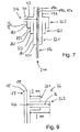
Figur 4 nochmals abgewandeltes Ausführungsbeispiel für eine Multiband-Auskoppelvorrichtung zur Speisung von drei Frequenzen (drei Frequenzbänder), die über zwei Antenneneinrichtungen ausgestrahlt oder empfangen werden; - Figur 8 :
ein bezüglich Figur 4 weiter entwickeltes Ausführungsbeispiel zur Speisung dreier übereinander angeordneter, in zwei Frequenzbereichen arbeitender Antenneneinrichtungen mittels einer vierfachen Koaxialleitung; und- Figur 9 :
- eine zu Figur 4 vergleichbare Ausführung, jedoch nur mit einfachem Innenleiter (beispielsweise als Blitzschutz für eine Zwei-Frequenzband-Einrichtung).
- FIG. 1a
- an embodiment of a two-region antenna in the schematic axial longitudinal cross section (dipole structure);
- FIG. 1b
- a schematic axial longitudinal cross section through an embodiment of two superimposed two-band antennas;
- FIG. 2:
- a known narrowband lightning protection device for a coaxial line according to the prior art;
- FIG. 3:
- an excerptionally schematic Axialschnittdarstellung to explain a principle of a feed and decoupling device according to the invention for feeding a triax line for a frequency band;
- FIG. 4:
- an inventive development of a multiband feed or decoupling device;
- FIG. 5:
- a schematic cross-sectional view taken along line VV in Figure 4;
- FIG. 6:
- a modified to Figure 4 embodiment;
- FIG. 7:
- an embodiment of a multi-band decoupling device for supplying three frequencies (three frequency bands), which is again modified for FIG. 4, and which is broadcast or received via two antenna devices;
- FIG. 8:
- an embodiment further developed with respect to Figure 4 for feeding three superposed, operating in two frequency ranges antenna devices by means of a quadruple coaxial line; and
- FIG. 9:
- a comparable to Figure 4 embodiment, but only with a simple inner conductor (for example, as lightning protection for a two-frequency band device).
Eine Mehr-Bereichs-Antenne 1 umfasst gemäß Figur 1a eine erste Antenne 3 mit zwei Dipolhälften 3' und 3", die im gezeigten Ausführungsbeispiel aus einem elektrisch leitenden Zylinderrohr gebildet sind. Die in der Figur obenliegende Dipolhälfte 3' ist dabei topfförmig gestaltet, d.h. an ihrem zur zweiten Dipolhälfte 3" angrenzenden Ende 7' topfförmig verschlossen.According to FIG. 1 a, a
Die Länge dieser Dipolhälften 3' und 3" hängt von dem zu übertragenden Frequenzbereich ab und ist im gezeigten Ausführungsbeispiel auf die Übertragung des niedrigeren GSM-Bandbereichs, d.h. entsprechend dem GSM-Mobilfunkstandard zur Übertragung des 900 MHz-Bereiches abgestimmt.The length of these
Zur Übertragung eines zweiten Frequenzbereiches, im gezeigten Ausführungsbeispiel von 1800 MHz, ist eine zweite dipolförmige Antenne vorgesehen, deren Dipolhälften 9' und 9" entsprechend dem höheren zu übertragenden Frequenzbereiches in der Länge kürzer dimensioniert, im gezeigten Ausführungsbeispiel aufgrund der doppelt so hohen Übertragungsfrequenz nur ca. halb so lang wie die Dipolhälften 3' und 3" sind.For transmission of a second frequency range, in the illustrated embodiment of 1800 MHz, a second dipole antenna is provided, the dipole halves 9 'and 9 "according to the higher frequency range to be transmitted shorter in length dimensioned in the illustrated embodiment due to the twice as high transmission frequency only approx are half as long as the dipole halves 3 'and 3 ".
Diese Dipolhälften 9' und 9" sind ebenfalls im gezeigten Ausführungsbeispiel rohr- oder zylinderförmig gestaltet, allerdings mit größerem Durchmesser als der Durchmesser der Dipolhälften 3' und 3", so dass die Dipolhälften der Antenne 9 mit kürzerer Länge innenliegend die Dipolhälften 3' und 3" mit größerer Längserstreckung aufnehmen und übergreifen können.These dipole halves 9 'and 9 "are also designed tubular or cylindrical in the embodiment shown, but with a larger diameter than the diameter of the dipole halves 3' and 3", so that the dipole halves of the
Jeweils an den aneinander angrenzenden inneren Enden 7' und 7"der Dipolhälften sind die jeweils verschachtelt ineinander sitzenden Dipolhälften 3' und 9' bzw. 3" und 9" gemeinsam topfförmig gestaltet und dadurch unter Bildung eines Kurzschlusses 11' bzw. 11" elektrisch miteinander verbunden.Respectively at the adjoining inner ends 7 'and 7 "of the dipole halves, the respective interleaved
In der Zeichnung ist auch dargestellt, dass die unteren Dipolhälften 3" und 9" über einen Außenleiter 15 einer koaxialen Speiseleitung 17 gespeist werden, wobei der Innenleiter 19 über den Kurzschluss 11" am Ende 7" der unteren Dipolhälfte hinaus bis zu den topfförmigen Kurzschlussverbindungen 11' der oberen Dipolhälften 3' und 9' hinausgeführt und dort elektrisch und mechanisch mit den topfförmigen Böden dieser Dipolhälften 3' und 9' verbunden ist.The drawing also shows that the
Bei diesem Aufbau ist es möglich, über einen einzigen koaxialen Anschluss 21 beide verschachtelt ineinander angeordnete Dipolantennen 3 und 9 zu speisen.In this construction, it is possible to feed both nested interdigitated
Die Funktionsweise der Antenne ist derart, dass die für das höheren Frequenzband vorgesehenen Dipolhälften in kürzerer Längserstreckung nach außen hin als Strahler, die Innenseite dieser topfförmigen Dipolhälften 9' bzw. 9" jedoch als Sperrtopf wirken. Diese Sperrtopfwirkung gewährleistet, dass keine Mantelwellen auf die mit größerer Längserstreckung vorgesehenen Dipolhälften der zweiten Antenne fortlaufen können.The mode of operation of the antenna is such that the dipole halves provided for the higher frequency band act as emitters in shorter longitudinal outward direction, but the inside of these cup-shaped
Für die zweite Antenne 3 mit den sich in größerer Länge erstreckenden Dipolhälften 3', 3" ist jedoch der Sperrtopf für die höhere Frequenz der äußeren rohr- oder topfförmigen Dipolhälften 9', 9" nicht "erkennbar" oder wirksam, so dass auch diese Dipolhälften nach außen hin wie Einzelstrahler wirken. Die Innenseite der unteren topfförmigen Dipolhälfte 3" wirkt jedoch als Sperrtopf. Diese Sperrtopfwirkung gewährleistet, dass keine Mantelwellen auf dem Außenleiter einer koaxialen Speiseleitung fortlaufen können.For the
Durch diesen Aufbau wird eine höchst kompakte Antennenanordnung geschaffen, die zudem eine bisher nicht gekannte optimale Rundstrahlcharakteristik und -eigenschaft aufweist; und dies bei vereinfachter Einspeisung über nur einen einzigen gemeinsamen Anschluss.By this construction, a highly compact antenna arrangement is created, which also has an unprecedented optimal omnidirectional characteristic and property; and this with simplified feed over only a single shared connection.
Abweichend vom gezeigten Ausführungsbeispiel müssen aber die Dipolhälften nicht zwangsweise rohr- oder topfförmig gestaltet sein. Anstelle eines runden Querschnitts für die Dipolhälften 3' bis 9" können auch eckige (n-polygonalförmige) oder auch sonstige von der Kreisform abweichende, beispielsweise oval gestaltete Dipolhälften in Betracht kommen. Es sind ferner auch solche Konstruktionen für die Dipolhälften denkbar, in denen die umlaufende Mantelfläche nicht zwangsweise geschlossen, sondern in mehrere einzelne räumlich gekrümmte oder sogar planare Elemente gegliedert ist, sofern diese an ihrem aneinander angrenzenden inneren Ende 7' bzw. 7" der Dipolhälften, an denen der oben erwähnte topfförmige Kurzschluss 11' bzw. 11" gebildet ist, elektrisch miteinander verbunden und dabei so ausgeführt sind, dass die erwähnte Sperrwirkung des jeweils äußeren Topfes gegenüber dem inneren Topf aufrecht erhalten wird, um sicherzustellen, dass sich keine Mantelwellen ausbreiten können.Notwithstanding the embodiment shown but the dipole halves need not necessarily be designed tubular or cup-shaped. Instead of a round cross section for the dipole halves 3 'to 9 ", it is also possible to use angular (n-polygonal) or other dipole halves deviating from the circular shape, for example oval-shaped designs circumferential outer surface is not necessarily closed, but is divided into several individual spatially curved or even planar elements, provided that at their adjacent
Strichliert ist in dem gezeigten Ausführungsbeispiel in der beigefügten Figur angedeutet, dass dieses Konstruktionsprinzip problemlos auf weitere Frequenzbänder ausgedehnt werden kann. Strichliert ist dabei angedeutet, dass beispielsweise nochmals ein weiterer äußerer Topf für Dipolhälften 25' bzw. 25" einer dritten Antenne 25 vorgesehen sein könnte, die für eine nochmals höhere Frequenz ausgelegt ist und deshalb eine nochmals kürzere Längserstreckung aufweist. Auch diese Dipolhälften 25' und 25" sind jeweils an ihrem aufeinander zuweisenden inneren Ende mit dem Ende der anderen Dipolhälfte kurzgeschlossen. Die Außenseite dieser Dipolhälften 25' und 25" wirken für diese Frequenz als Strahler, wobei die Innenseite bzgl. der nächsten inneren Dipolhälften als Sperrtöpfe wirken. Diese Sperrtöpfe sind aber für die verschachtelt innenliegenden Dipolhälften wiederum nicht wirksam.Dashed line is indicated in the embodiment shown in the accompanying figure that this design principle can be easily extended to other frequency bands. Dashed lines indicate that, for example, a further outer pot could be provided for
Abweichend zu dem Ausführungsbeispiel nach Figur 1a könnte anstelle der oberen zu innerst liegenden Dipolhälfte 3' auch eine nicht topf- oder hohlzylinderförmige oder dergleichen gebildete Dipolhälfte, d.h. z.B. auch eine stabförmige Dipolhälfte einegesetzt werden, da diese Dipolhälfte im Inneren weder eine weitere Dipolhälfte noch einen Speiseleitungsanschluss aufnehmen muss.In contrast to the exemplary embodiment according to FIG. 1 a, instead of the upper inward-lying dipole half 3 ', it would also be possible to use a dip-well or hollow-cylindrical or the like dipole half, i. e.g. also a rod-shaped dipole half be set, since this dipole half must accommodate neither another half of the dipole nor a feed line connection inside.
Eine Mehr-Bereichs-Antenne gemäß Figur 1b umfasst eine erste Antenneneinrichtung A, die von ihrem Aufbau der Antenneneinrichtung gemäß Figur 1a entspricht. Die in Figur 1a verwendeten Bezugszeichen haben in Figur 1b bezüglich der Antenneneirichtung A lediglich die Buchstabenerweiterung "a" erhalten.A multi-region antenna according to FIG. 1b comprises a first antenna device A, which corresponds to the structure of the antenna device according to FIG. 1a. The reference symbols used in FIG. 1 a have only the letter extension "a" with respect to the antenna device A in FIG. 1b.
Die Antenneneinrichtung gemäß Figur 1b umfasst aber auch eine zweite Mehr-Bereichs-Antenneneinrichtung B, die vom Prinzip her gleich aufgebaut ist, wobei für diese zweite Antenneneinrichtung B bei den Bezugszeichen die Buchstabenerweiterung "b" in Abweichung zu "a" für die erste Mehr-Bereichs-Antenneneinrichtung A verwendet ist.The antenna device according to FIG. 1b, however, also comprises a second multi-range antenna device B, which is constructed basically the same, wherein for this second antenna device B at the reference numerals the letter extension "b" deviates from "a" for the first multiple antenna device B. Area antenna device A is used.
Bei diesem Aufbau ist es möglich, über einen einzigen koaxialen Anschluss 21a, an welchem eine koaxiale Anschlussleitung 52 mit einem Außenleiter 51 und einem Innenleiter 53 angesteckt ist, und die davon ausgehende Speiseleitung 17 mit dem Außenleiter 15a und dem Innenleiter 19a, beide verschachtelt ineinander angeordnete Dipolantennen 3a und 9a zu speisen.In this construction, it is possible to connect to the
Bei einer derartigen Antenne gemäß Figur 1b ist es also wünschenswert, wenn beispielsweise über eine dreifache Koaxialleitung 17, d.h. über die innere Koaxialleitung 17a mit dem Innenleiter 19a und dem Außenleiter 15a, die obere Mehr-Bereichs-Antenneneinrichtung A und über die äußere Koaxialleitung 17b mit dem Innenleiter 19b und dem Außenleiter 15b, die untere Antenneneinrichtung B gespeist werden könnte. Dabei spielt der mittlere Koaxialleiter also eine Doppelfunktion, denn er ist zum einen der Außenleiter 15a für die obere Antenneneinrichtung A und gleichzeitig der Innenleiter 19b für die untere Antenneneinrichtung B. Da allerdings der Außenleiter 15a der inneren Koaxialleitung auf Masse liegt (z.B. durch die koaxiale Anschlussverbindung 21a) und dieser äußere Leiter 15a des inneren Koaxialkabels 17a gleichzeitig den Innenleiter 19b des äußeren Koaxialkabels 17b darstellt, hat dies zur Folge, dass Innen- und Außenleiter 19b, 15b des äußeren Koaxialkabels 17b auf gleichem Potential, nämlich Masse, liegen.In such an antenna according to Figure 1b, it is therefore desirable, for example, if a threefold
Von daher werden zusätzliche technische Maßnahmen notwendig, die eine entsprechende Einspeisung zum Betrieb der oberen und unteren Antenneneinrichtung A bzw. B ermöglichen und die es zudem erlauben, einen Innenleiter auf das Potential des Außenleiters zu legen.Therefore, additional technical measures are necessary that allow a corresponding feed to operate the upper and lower antenna device A and B and also allow it to place an inner conductor to the potential of the outer conductor.
Anhand von Figur 2 ist eine nach dem Stand der Technik bekannte Lösung für eine Koaxialleitung 17 mit einem Innenleiter 19 und einem Außenleiter 15 gezeigt, der an einer Anschlussstelle 46 eine koaxiale Stichleitung SL aufweist, deren koaxialer Außenleiter AL mit dem Außenleiter 15 und deren Innenleiter IL mit dem Innenleiter 19 der Koaxialleitung 17 elektrisch verbunden ist. Am Ende der Stichleitung ist der Außenleiter AL mit dem zugehörigen Innenleiter IL über einen topfförmigen Kurzschluss KS kurzgeschlossen, worüber also der Innenleiter 19 mit dem Außenleiter 15 der Koaxialleitung 17 verbunden ist. Dies erfolgt für eine bestimmte Frequenz bzw. ein bestimmtes Frequenzband derart, dass die elektrische Länge der koaxialen Stichleitung LS 1 = λ/4 entspricht, wobei λ die Wellenlänge der betreffenden Frequenz bzw. des betreffenden Frequenzbandes ist. Dies ist aber immer nur schmalbandig für eine bestimmte Frequenz und damit für eine bestimmte Wellenlänge möglich.FIG. 2 shows a solution known from the prior art for a
Sollte die in Figur 1 beschriebene Antenne mit einer oberen und einer unteren Antenneneinrichtung nur in einem Frequenzband betrieben werden, so lässt sich dies über eine gemeinsame Mehrfach-Koaxialleitung mit einer in Figur 3 wiedergegebenen erfindungsgemäßen Speise- oder Auskoppelvorrichtung realisieren.If the antenna described in FIG. 1 is operated with only one frequency band with an upper and a lower antenna device, this can be realized via a common multiple coaxial line with a feed or decoupling device according to the invention shown in FIG.
Das Ausführungsbeispiel gemäß Figur 3 unterscheidet sich von Figur 2 unter anderem dadurch, dass am Anschlusspunkt 46 die Koaxialleitung 17 einen rechtwinkeligen Knick vollführt, also von oben kommend nicht nach unten, wie in Figur 2 gezeigt, weitergeführt, sondern am Anschlusspunkt 46 nach links weggeführt ist. Die in Figur 2 gezeigte Stichleitung ist bei dem Ausführungsbeispiel nach Figur 3 in axialer Verlängerung der oberhalb des Anschlusspunktes 46 vertikal nach oben verlaufenden koaxialen Anschlussleitung liegend gezeichnet. Ein weiterer Unterschied liegt darin, dass der in Figur 2 gezeigte Innenleiter 19 in Figur 3 durch eine Koaxialleitung 17a ersetzt ist.The exemplary embodiment according to FIG. 3 differs from FIG. 2, inter alia, in that at the
Über ein zu einem Koaxialanschluss 21a führendes Koaxialkabel 52 mit einem Innenleiter 53 und einem Außenleiter 51 kann nunmehr eine elektrische Verbindung zum Innenleiter 19a bzw. dem Außenleiter 15a der inneren Koaxialleitung 17a zur Speisung der oberen Antenneneinrichtung A hergestellt werden, wobei über eine zweite Speiseleitung 42 mit einem Innenleiter 43 und einem Außenleiter 41 über einen koaxialen Anschluss 21b und eine koaxiale Zwischenleitung 62 mit einem Innenleiter 63 und einem Außenleiter 61 die äußere Koaxialleitung 17b entsprechend gespeist wird, wozu am Anschlusspunkt 46 letztlich der Innenleiter 63 der zweiten Anschlussleitung 42 mit dem Innenleiter 19b und der Außenleiter 41 mit dem Außenleiter 15b der Speiseleitung 17b elektrisch verbunden ist. Im elektrischen Sinne stellt somit die Zwischenleitung 62 die äußere koaxiale Speiseleitung 17b mit dem Innenleiter 19b und dem Außenleiter 15b dar. Wird, wie in diesem Ausführungsbeispiel, die in Figur 1 gezeigte obere und untere Antenneneinrichtung A bzw. B nur in einem Frequenzband betrieben, so erfolgt die Einspeisung am Anschlusspunkt 46 derart, dass die Länge 1 der koaxialen Stichleitung SL bzw. des zugehörigen Außenleiters AL, l = λ/4 der in Rede stehenden Frequenz entspricht. Durch den topfförmigen Kurzschluss KS, wodurch der äußere Außenleiter 15b mit dem inneren Außenleiter 15a elektrisch kurzgeschlossen ist, wird an den Anschlusspunkt 46 ein Leerlauf transformiert. Von daher kann die entsprechende Antenneneinrichtung zum Betrieb in einem Frequenzband mit der anhand von Figur 3 erläuterten Speise- bzw. Auskoppelvorrichtung gespeist werden.Via a
Soll demgegenüber aber die in Figur 1 beschriebene Antenne mit zwei übereinander angeordneten Antenneneinrichtungen A und B in zwei Frequenzbändern betrieben werden, so ist eine in Figur 4 erläuterte Speise- oder Auskoppelvorrichtung notwendig, die nachfolgend erörtert wird.In contrast, however, the antenna described in Figure 1 with two superimposed antenna devices A and B are operated in two frequency bands, as explained in Figure 4 feed or decoupling device is necessary, which will be discussed below.
Für die in Figur 1 wiedergegebene Antenneneinrichtung zum Betrieb beispielsweise zweier unterschiedlicher Frequenzbereiche werden zwei jeweils über einen Kurzschluss KS1 bzw. KS2 kurzgeschlossene koaxiale λ/4-Leitungen verschachtelt, wobei die äußere λ1/4-Leitung SL1 für die Anpassung bezüglich der höheren Frequenz (beispielsweise für die Übertragung des 1800 MHz-Frequenzbereiches z.B. PCN) und die innere λ2/4-Leitung SL2 für die Anpassung bezüglich der niedrigeren Frequenz, beispielsweise des 900 MHz-Bereiches (z.B. GSM) dient. Dadurch ist der Außenleiter AL1 der ersten Stichleitung SL1 am Ende der Stichleitung (bezogen auf die Einspeisestelle 46) mit einem radialen, d.h. ring- oder topfförmigen Kurzschluss KS1 mit dem Außenleiter AL2 der koaxialen Stichleitung SL2 und der Außenleiter AL2 der Stichleitung SL2 wiederum über einen weiteren radialen, d.h. ring- oder topfförmigen Kurzschluss KS2 mit dem Innenleiter 19b der äußeren Koaxialleitung kurzgeschlossen. Der innere Außenleiter AL2 endet frei benachbart des Anschlusspunktes 46.Two short-circuited in each case a short-circuit KS1 or KS2 coaxial λ / 4 lines are interleaved for reproduced in Figure 1 antenna device to operate, for example, two different frequency ranges, wherein the outer λ 1/4 line SL1 (for adjustment with respect to the higher frequency SL2 (for adjustment with respect to the lower frequency, such as the 900 MHz range, for example, GSM) is used for example for the transmission of the 1800 MHz frequency range, for example, PCN) and the inner λ 2/4-line. As a result, the outer conductor AL1 of the first stub SL1 at the end of the stub (with respect to the feed point 46) with a radial, ie annular or cup-shaped short KS1 with the outer conductor AL2 of the coaxial stub SL2 and the outer conductor AL2 of the stub SL2 turn over another radial, ie ring or cup-shaped short KS2 shorted to the inner conductor 19b of the outer coaxial line. The inner outer conductor AL2 terminates freely adjacent to the
Gemäß dem Ausführungsbeispiel wird also über einen ersten Koaxialkabelanschluss 21a die obere Antenneneinrichtung A gespeist, wobei der Innenleiter 53 in den Innenleiter 19a und der Außenleiter 51 der Anschlussleitung 52 in den Außenleiter 15a der koaxialen Speiseleitung 17a für die obere Antenneneinrichtung A übergeht.According to the embodiment, therefore, the upper antenna device A is fed via a first coaxial cable connection 21a, wherein the
Über einen zweiten Koaxialkabelanschluss 21b und eine nachfolgende Zwischenleitung 42 mit einem zugehörigen Außenleiter 41 und einem Innenleiter 43 erfolgt die Speisung der unteren Antenneneinrichtung B derart, dass der Innenleiter 43 mit dem Innenleiter 19b der koaxialen Speiseleitung 17 und der Außenleiter 41 der zweiten Koaxialkabel-Anschlussleitung mit dem Außenleiter 15b der Triax-Leitung elektrisch verbunden sind. Am unteren Ende der Einspeis- und Auskoppel-Vorrichtung ist dabei durch die koaxialförmig verschachtelten und an ihrem Ende jeweils kurzgeschlossenen Stichleitungen SL1, SL2 in Abhängigkeit der Wellenlänge λ1/4 und λ2/4 bezogen auf die beiden zu übertragenden Frequenzbereiche die gewünschten Anpassung durchgeführt, wobei die erste topfförmige Kurzschlussleitung KS1 etwa in der axialen Mitte bezogen auf die elektrische Länge der koaxialen Stichleitung SL2 in Anpassung an die in diesem Ausführungsbeispiel zu übertragenen Frequenzbändern von 900 MHz und 1800 MHz liegt.Via a second coaxial cable connection 21b and a subsequent
Die erläuterten beiden kurzgeschlossenen λ/4-Stichleitungen SL1 und SL2 sind also so in Reihe geschaltet, dass die zugehörigen Kurzschlüsse KS1 und KS2 bezüglich des jeweiligen Frequenzbereiches am Anschlusspunkt 46 jeweils in einen Leerlauf transformiert werden.The explained two short-circuited λ / 4 stub lines SL1 and SL2 are thus connected in series such that the associated short circuits KS1 and KS2 are each transformed into an open circuit with respect to the respective frequency range at the
Anhand von Figur 6 ist gezeigt, dass das Konstruktionsprinzip der in Reihe geschalteten Kurzschlussleitung KS1 und KS2 auch in umgekehrter Reihenfolge verwirklichbar ist, wenn nämlich die λ2/4-Stichleitung SL2 (mit dem Außenleiter AL2) für die niedrigere Frequenz außenliegend und die λ1/4-Stichleitung SL1 (mit dem Außenleiter AL1) für die höhere Frequenz (konzentrisch) zur ersten Stichleitung innenliegend angeordnet ist. Allerdings ist der Konstruktionsaufwand hierfür etwas höher.Referring to Figure 6 is shown that the design principle of the series connected short-circuit line KS1 and KS2 can also be realized in reverse order, namely, when the λ 2/4 spur line SL2 outboard (to the outer conductor AL2) for the lower frequency and the λ 1 / 4-stub cable SL1 (with outer conductor AL1) for the higher frequency (concentric) to the first stub line is arranged inside. However, the design effort for this is slightly higher.
In Ergänzung zu den vorstehend erläuterten Ausführungsbeispielen können auch mehrere, beispielsweise drei kurzgeschlossene λ/4-Leitungen ineinander verschachtelt und somit mehrere Frequenzbänder (z.B. drei Frequenzbänder) gespeist bzw. ausgekoppelt werden.In addition to the exemplary embodiments explained above, several, for example three short-circuited λ / 4 lines can be interleaved and thus several frequency bands (for example three frequency bands) fed or coupled out.
Anhand von Figur 7 ist nur das Konstruktionsprinzip für den Fall erläutert, dass in eine entsprechende Mehrfach-Koaxial-Speiseleitung 17 drei versetzt zueinander liegende Frequenzbänder eingespeist werden sollen, wozu eine dritte Kurzschlussverbindung KS3 zur Anpassung vorgesehen ist, wobei in diesem Ausführungsbeispiel davon ausgegangen wird, dass der dritte Kurzschluss KS3 eine Länge λ3/4 für die Übertragung eines noch höheren Frequenzbereiches aufweist.With reference to FIG. 7, only the design principle is explained for the case in which three frequency bands offset from each other are to be fed into a corresponding multiple
Anhand von Figur 8 ist ein bezüglich Figur 4 nochmals abgewandeltes Ausführungsbeispiel für eine Speise- oder Auskoppelvorrichtung gezeigt, bei welcher beispielsweise in Ergänzung zu dem Ausführungsbeispiel nach Figur 1 drei übereinander angeordnete Antenneneinrichtungen gemeinsam über eine Mehrfach-Koaxialkabelleitung 17 gespeist werden können, die in zwei Frequenzbereichen arbeiten. Dort wird kaskadiert über zwei anhand von Figur 4 erläuterten Speise- und Auskoppelvorrichtungen jeweils eine entsprechende Anpassung zwischen einem äußeren Außenleiter und einem zugehörigen Innenleiter gezeigt, der gleichzeitig der Außenleiter für einen nächsten inneren Innenleiter darstellt. Bei jeder der vorgesehenen Stufen wird jeweils über die beschriebene erfindungsgemäße Speise- oder Auskoppelvorrichtung 101 bzw. 103 ein Außenleiter mit seinem zugehörigen Innenleiter auf ein gemeinsames Potential gelegt. Das Ausführungsbeispiel gemäß Figur 8 zeigt, wie auch dieses Verfahren mehrstufig mit weiteren Außenleitern AL1, AL2 und Kurzschlüssen KS3, KS4 ausgebaut werden kann.FIG. 8 shows a further embodiment, modified with respect to FIG. 4, of a feeding or decoupling device, in which, for example, in addition to the exemplary embodiment according to FIG. 1, three superimposed antenna devices can be fed together via a multiple
Anhand von Figur 9 ist noch eine Speise- und Auskoppelvorrichtung für eine einfache Koaxialleitung 17 gezeigt, die jedoch mit einem breitbandigen Blitzschutz versehen ist, im gezeigten Ausführungsbeispiel für zwei Frequenzbandbereiche.A feed and decoupling device for a simple
Die Funktion entspricht dabei dem Ausführungsbeispiel nach Figur 4, wobei in Abweichung dazu anstelle des in Figur 4 gezeigten inneren Koaxialleiters 17a nur ein einfacher Innenleiter 15 vorgesehen ist, so dass dieser Innenleiter ohne Krümmung in Axialrichtung verlaufend durchgeführt und die beiden verschachtelten und an dem Ende wiederum kurzgeschlossenen Stichleitung SL1 und SL2 rechtwinklig von dieser Koaxialleitung 17 abzweigen. Bezüglich Aufbau und Funktionsweise wird ansonsten auf das Ausführungsbeispiel nach Figur 4 verwiesen, das bezüglich des in Figur 4 dargestellten äußeren Koaxialleiters 17b und dem Außenleiter 15b und dem Innenleiter 19b analog auf das Ausführungsbeispiel gemäß Figur 9 übertragbar ist.In this case, the function corresponds to the exemplary embodiment according to FIG. 4, except that instead of the inner
Claims (20)
- Multi-range antenna with an antenna device (A) with at least two antennae, namely with a first antenna for a first frequency range and with a second antenna for a second frequency range which is higher than the first frequency range, with the following features:- The first antenna (3) and the second antenna (9) belonging to the antenna device (A) are integrated into one another and arranged in interlaced fashion,- The first antenna (3) and the second antenna (9) comprise in each case two dipole halves (3', 3"; 9', 9"; 25', 25"), namely dipole halves (3", 9", 25") on the power feed line side, which are located facing a coaxial power feed line arrangement (17), and outer dipole halves (3', 9', 25') which are located facing away from the coaxial power feed line arrangement (17),- The dipole halves (3', 3"; 9', 9"; 25', 25") of the minimum of two antennae (3, 9, 25) are short-circuited at their mutually adjacent inner ends (7', 7") by means of a short-circuit (11', 11"), and extend from there in different lengths as a function of the frequency range to be transmitted, and- The coaxial power feed line arrangement (17) comprises an outer conductor (15) and an inner conductor (19), wherein the outer dipole halves (3', 9', 25') are fed via the inner conductor (19) and the feed line-side dipole halves (3", 9", 25") are fed via the outer conductor (15),characterised by the following further features:- The power feed line-side dipole halves (3", 9", 25") of the minimum of two antennae (3, 9, 25) are designed at least in the electrical respect as a cup or box shape,- The outer dipole halves (3', 9', 25') of the minimum of two antennae (3, 9, 25) are designed at least in the electrical respect as a cup or box shape, and- The dipole halves (3', 9', 25'; 3", 9", 25") for the transmission of the lower frequency range in each case lie inside the dipole halves (9', 25'; 9", 25") which are provided for the transmission of the higher frequency range in each case.
- Multi-range antenna according to Claim 1, characterised in that the dipole halves (3', 9', 25'; 3", 9", 25") are arranged coaxially to one another.
- Multi-range antenna according either of Claims 1 and 2, characterised in that the dipole halves (3', 9', 25'; 3", 9", 25") are designed in cross-section transverse to the dipole longitudinal extension as circular, cornered, n-polygonal, or oval.
- Multi-range antenna according to any one of Claims 1 to 3, characterised in that the cup or box-shaped dipole halves (3', 9', 25'; 3", 9", 25") comprise an electrically conductive dipole wall, which is enclosed in the circumferential direction.
- Multi-range antenna according to any one of Claims 1 to 3, characterised in that the cup or box-shaped dipole halves (3', 9', 25'; 3", 9", 25") comprise an electrically conductive dipole wall, which is divided in the circumferential direction into several individual segments, which are electrically short-circuited with one another at the inner end (7', 7") of the dipole halves (3', 9', 25' ; 3", 9", 25").
- Multi-range antenna according to any one of Claims 1 to 5, characterised in that the multiple antennae (3, 9, 25) are fed via a common connection (21).
- Multi-range antenna according to any one of Claims 1 to 6, characterised in that the multiple antennae (3, 9, 25) are fed via a common coaxial power feed line arrangement (17).
- Multi-range antenna according to Claim 7, characterised in that the coaxial power feed line arrangement (17) serving to feed the power serves as a mechanical support and mounting for the multi-range antenna (1) and in particular is designed as an upright tube.
- Multi-range antenna according to Claim 8, characterised in that the dipole halves (3", 9", 25") fed via the outer conductor (15) are mechanically supported and held by the outer conductor (15).
- Multi-range antenna according to any one of Claims 1 to 9, characterised in that the inner conductor (19) is guided out over the outer conductor (15) as far as the cup-shaped short-circuit devices (11') of the dipole halves (3', 9', 25') which face away from the coaxial power feed line arrangement (17) and is there connected electrically and mechanically to the cup-shaped bases of these dipole halves (3', 9').
- Multi- range antenna according to any one of Claims 1 to 10, characterised by the following features:- As well as the antenna device (A) with at least two antennae (3a, 9a, 25a) at least one further antenna device (B) is provided, with at least two antennae (3b, 9b, 25b),- The dipole halves (3'b, 3"b; 9'b, 9"b; 25'b, 25"b) belonging to the antenna device (B) are designed as cup-shaped or box-shaped,- The antenna device (B) forms a lower antenna device (B) to the upper antenna device (A),- The coaxial power feed line arrangement (17) leading to the antenna device (A) is guided axially through the antenna device (B), and specifically through the innermost cup-shaped or box-shaped or similar shaped dipole halves (3'b, 3"b),- The power feed line arrangement (17) is designed as a multiple coaxial line (17a, 17b) with an outer coaxial conductor (17b) and an inner coaxial conductor (17a), in such a way that the outer conductor (15b) of the outer coaxial conductor (17b) of the multiple coaxial line (17a, 17b) is connected to the dipole halves (3"b, 9"b, 25"b) of the antenna device (B) lying on the power feed line side and one of the inner conductors (19b) belonging to the outer coaxial conductor (17b) is connected to the outer dipole halves (3'b, 9'b, 25'b) of the antenna device (B),
and- the outer conductor (15a) of the inner coaxial line (17a) of the multiple coaxial line (17a, 17b) guided out over the antenna device (B) is connected to the dipole halves (3"a, 9"a, 25"a) located on the power feed line side, and the inner conductor (19a) of the inner coaxial line (17a) is connected to the outer dipole halves (3'a, 9'a, 25'a) of the antenna device (A) facing away from the coaxial power feed line arrangement (17). - Multi-range antenna according to Claim 11, characterised in that at least one three-fold coaxial line is provided as a power feed line (17) for the two antenna devices, wherein the inner conductor (19b) of the outer coaxial line (17b) forms the outer conductor (15a) of the inner coaxial line (17a).
- Multi-range antenna according to either of Claims 11 and 12, characterised by the following features:- One power feed or decoupling device is provided for the multiple coaxial line (17a, 17b) for the multi-range antenna with the minimum of two antenna devices (A, B),- In addition, at least two interlaced, coaxial spur lines (SL; SL1, SL2) are provided, which are connected in series,- The electrical length of the outer coaxial spur line (SL1 or SL2) corresponds to λ1/4 with a wavelength λ1 of the first frequency range,- The electrical length of the inner coaxial spur line (SL2 or SL1) corresponds to λ2/4 with a wavelength λ2 of the second frequency range,- The outer conductor (AL1 or AL2) of the outer coaxial spur line (SL1 or SL2) is short-circuited at one of its ends by means of a short-circuit (KS1 or KS2) with the outer conductor (AL2 or AL1) of the inner coaxial spur line (SL2 or SL1),- The outer conductor (AL2 or AL1) of the innermost coaxial spur line (SL2 or SL1) is connected at one of its ends by means of a short-circuit (KS2 or KS1) to the inner conductor (IL; 19b) of this coaxial spur line (SL2 or SL1),- The outer conductor (AL1 or AL2) of the outermost coaxial spur line (SL1 or SL2) is connected to the outer conductor (15; 15b) of the multiple coaxial line (17, 17b), and- The inner conductor (IL, 19b) of the innermost spur line (SL2 or SL1) is electrically connected at a connection point (46) to the inner conductor (19; 19b) of the power feed line (17, 17b).
- Multi-range antenna according to any one of Claims 10 to 13, characterised in that the power feed line arrangement (17) consists at least of one double multiple coaxial line (17a, 17b), wherein the inner conductor (IL) of the inner spur line (SL1 or SL2) is designed as a coaxial power feed line (17a), which implements the short-circuit connection (KS2 or KS1) between the outer conductor (AL2 or AL1) and the inner conductor (IL, 19b) pertaining to it of the inner spur line (SL2 or SL1).
- Multi-range antenna according to any one of Claims 10 to 14, characterised in that the outer conductor (AL1, AL2) of the outer coaxial spur line (SL1 or SL2) is electrically connected to the outer conductor (15b) of the outer coaxial power feed line (17b) and the inner conductor (IL) of the outer spur line (SL1 or SL2), which simultaneously forms the outer conductor (15a) of the inner power feed line (17a), is electrically connected at a connection point (46) to the inner conductor (19b) of the outer power feed line (17b).
- Multi-range antenna according to any one of Claims 10 to 15, characterised in that the short-circuits (KS1, KS2) of the spur line (SL1, SL2) are designed in cup shape or ring shape.
- Multi-range antenna according to any one of Claims 10 to 16, characterised in that the λ2/4 spur line (SL2) for the lower frequency range is arranged on the outside in relation to the λ1/4 spur line (SL1) for the higher frequency range.
- Multi-range antenna according to any one of Claims 10 to 16, characterised in that the λ1/4 spur line (SL1) for the higher frequency range is arranged on the outside in relation to the λ2/4 spur line (SL2) for the lower frequency range.
- Multi-range antenna according to any one of Claims 10 to 18, characterised in that one or more inner conductors (19a, 19b), as well as one or more outer conductors (15a, 15b), of a multiple coaxial line (17a, 17b) are laid on the same potential by means of the power feed device or decoupling device.
- Multi-range antenna according to any one of Claims 10 to 19, characterised in that the minimum of two interlaced spur lines (SL1, SL2), by way of adaptation to the frequency ranges to be transmitted, have an electrical length of such a nature that the short-circuit (KS1, KS2) provided in each case at the individual end of the spur line (SL1, SL2) is transformed at the infeed or connection point (46) into a no-load element.
Applications Claiming Priority (5)
| Application Number | Priority Date | Filing Date | Title |
|---|---|---|---|
| DE19920978 | 1999-05-06 | ||
| DE19920980A DE19920980C2 (en) | 1999-05-06 | 1999-05-06 | Feeding or decoupling device for a coaxial line, in particular for a multiple coaxial line |
| DE19920980 | 1999-05-06 | ||
| DE19920978 | 1999-05-06 | ||
| PCT/EP2000/003999 WO2000069018A1 (en) | 1999-05-06 | 2000-05-04 | Multi-frequency band antenna |
Publications (2)
| Publication Number | Publication Date |
|---|---|
| EP1095426A1 EP1095426A1 (en) | 2001-05-02 |
| EP1095426B1 true EP1095426B1 (en) | 2007-12-19 |
Family
ID=26053260
Family Applications (1)
| Application Number | Title | Priority Date | Filing Date |
|---|---|---|---|
| EP00931113A Expired - Lifetime EP1095426B1 (en) | 1999-05-06 | 2000-05-04 | Multi-frequency band antenna |
Country Status (14)
| Country | Link |
|---|---|
| US (1) | US6421024B1 (en) |
| EP (1) | EP1095426B1 (en) |
| JP (1) | JP2002544692A (en) |
| KR (1) | KR100610995B1 (en) |
| CN (1) | CN1171353C (en) |
| AT (1) | ATE381794T1 (en) |
| AU (1) | AU762334B2 (en) |
| BR (1) | BR0006101A (en) |
| CA (1) | CA2336613C (en) |
| DE (1) | DE50014859D1 (en) |
| ES (1) | ES2296620T3 (en) |
| HK (1) | HK1039217A1 (en) |
| NZ (1) | NZ508835A (en) |
| WO (1) | WO2000069018A1 (en) |
Families Citing this family (26)
| Publication number | Priority date | Publication date | Assignee | Title |
|---|---|---|---|---|
| EP1526604A1 (en) | 1999-09-20 | 2005-04-27 | Fractus, S.A. | Multilevel antenna |
| US6552692B1 (en) * | 2001-10-30 | 2003-04-22 | Andrew Corporation | Dual band sleeve dipole antenna |
| ATE405009T1 (en) * | 2002-01-31 | 2008-08-15 | Galtronics Ltd | MULTI-BAND SLEEVE DIPOLANTENNA |
| CN100369322C (en) * | 2003-02-09 | 2008-02-13 | 垠旺精密股份有限公司 | Plane surface multiple frequency band omnidirectional radiation field antenna |
| TWI251957B (en) * | 2004-03-26 | 2006-03-21 | Hon Hai Prec Ind Co Ltd | Dual-band dipole antenna |
| CN2766358Y (en) * | 2004-04-29 | 2006-03-22 | 富士康(昆山)电脑接插件有限公司 | Dual-frequency dipole antenna |
| WO2006024516A1 (en) * | 2004-08-31 | 2006-03-09 | Fractus, S.A. | Slim multi-band antenna array for cellular base stations |
| TWI241745B (en) * | 2004-12-24 | 2005-10-11 | Advanced Connectek Inc | Ultra-wideband dipole antenna |
| JP4308786B2 (en) * | 2005-02-24 | 2009-08-05 | パナソニック株式会社 | Portable radio |
| ATE544194T1 (en) | 2005-10-14 | 2012-02-15 | Fractus Sa | SLIM TRIPLE BAND ANTENNA ARRAY FOR CELLULAR BASE STATIONS |
| US20070139289A1 (en) * | 2005-12-20 | 2007-06-21 | Arcadyan Technology Corporation | Dipole antenna |
| KR100688283B1 (en) * | 2006-01-17 | 2007-03-02 | (주)에이스안테나 | Wireless communication antenna |
| US7327325B2 (en) * | 2006-04-14 | 2008-02-05 | Spx Corporation | Vertically polarized traveling wave antenna apparatus and method |
| US7586453B2 (en) * | 2006-12-19 | 2009-09-08 | Bae Systems Information And Electronic Systems Integration Inc. | Vehicular multiband antenna |
| JP5048012B2 (en) * | 2008-05-12 | 2012-10-17 | 日本アンテナ株式会社 | Collinear antenna |
| US20110287731A1 (en) * | 2009-02-02 | 2011-11-24 | Kazutoshi Hase | Antenna and reception apparatus provided with antenna |
| KR101038655B1 (en) * | 2010-02-10 | 2011-06-02 | 주식회사 모비텍 | Multi-band rod antenna convertible of operating frequency with broadband using coupling |
| CN101908669A (en) * | 2010-06-30 | 2010-12-08 | 苏州市吴通天线有限公司 | Four-branch multi-frequency cylindrical dipole antenna |
| CN102447160A (en) * | 2010-10-10 | 2012-05-09 | 四川九洲电器集团有限责任公司 | Novel broadband omni-directional array antenna radiating element |
| US8593363B2 (en) | 2011-01-27 | 2013-11-26 | Tdk Corporation | End-fed sleeve dipole antenna comprising a ¾-wave transformer |
| US8497808B2 (en) * | 2011-04-08 | 2013-07-30 | Wang Electro-Opto Corporation | Ultra-wideband miniaturized omnidirectional antennas via multi-mode three-dimensional (3-D) traveling-wave (TW) |
| CN103545609B (en) * | 2013-11-06 | 2016-03-02 | 中国计量学院 | Tree-form branch structure three-frequency-band antenna |
| US9778368B2 (en) | 2014-09-07 | 2017-10-03 | Trimble Inc. | Satellite navigation using side by side antennas |
| CN109962341A (en) * | 2017-12-22 | 2019-07-02 | 网件公司 | Antenna structure and relevant building and application method |
| CN108183322B (en) * | 2017-12-28 | 2024-02-06 | 东莞市仁丰电子科技有限公司 | Multiband three-in-one antenna |
| US11024982B2 (en) * | 2019-03-21 | 2021-06-01 | Samsung Electro-Mechanics Co., Ltd. | Antenna apparatus |
Family Cites Families (10)
| Publication number | Priority date | Publication date | Assignee | Title |
|---|---|---|---|---|
| US3022507A (en) | 1953-10-29 | 1962-02-20 | Antenna Engineering Lab | Multi-frequency antenna |
| SE402187B (en) | 1975-12-18 | 1978-06-19 | Philips Svenska Ab | BROADBAND DIPOLANT ANT |
| JPS55123203A (en) | 1979-03-16 | 1980-09-22 | Yoshiyuki Kino | Antenna |
| JPH0736488B2 (en) | 1987-01-14 | 1995-04-19 | 松下電工株式会社 | Phase difference feed type antenna |
| US4963879A (en) | 1989-07-31 | 1990-10-16 | Alliance Telecommunications Corp. | Double skirt omnidirectional dipole antenna |
| US5248988A (en) * | 1989-12-12 | 1993-09-28 | Nippon Antenna Co., Ltd. | Antenna used for a plurality of frequencies in common |
| US5440317A (en) * | 1993-05-17 | 1995-08-08 | At&T Corp. | Antenna assembly for a portable transceiver |
| US5521608A (en) | 1994-02-24 | 1996-05-28 | Rockwell International | Multibay coplanar direction finding antenna |
| US5604506A (en) * | 1994-12-13 | 1997-02-18 | Trimble Navigation Limited | Dual frequency vertical antenna |
| KR19990001739A (en) * | 1997-06-17 | 1999-01-15 | 윤종용 | Dual band antenna for mobile communication |
-
2000
- 2000-05-04 WO PCT/EP2000/003999 patent/WO2000069018A1/en active IP Right Grant
- 2000-05-04 EP EP00931113A patent/EP1095426B1/en not_active Expired - Lifetime
- 2000-05-04 KR KR1020007014524A patent/KR100610995B1/en not_active IP Right Cessation
- 2000-05-04 AT AT00931113T patent/ATE381794T1/en not_active IP Right Cessation
- 2000-05-04 NZ NZ508835A patent/NZ508835A/en not_active IP Right Cessation
- 2000-05-04 US US09/743,092 patent/US6421024B1/en not_active Expired - Lifetime
- 2000-05-04 ES ES00931113T patent/ES2296620T3/en not_active Expired - Lifetime
- 2000-05-04 DE DE50014859T patent/DE50014859D1/en not_active Expired - Lifetime
- 2000-05-04 JP JP2000617517A patent/JP2002544692A/en active Pending
- 2000-05-04 CN CNB008007780A patent/CN1171353C/en not_active Expired - Fee Related
- 2000-05-04 BR BR0006101-8A patent/BR0006101A/en not_active IP Right Cessation
- 2000-05-04 CA CA002336613A patent/CA2336613C/en not_active Expired - Fee Related
- 2000-05-04 AU AU49166/00A patent/AU762334B2/en not_active Ceased
-
2001
- 2001-12-14 HK HK01108797A patent/HK1039217A1/en not_active IP Right Cessation
Also Published As
| Publication number | Publication date |
|---|---|
| KR20010053060A (en) | 2001-06-25 |
| EP1095426A1 (en) | 2001-05-02 |
| ATE381794T1 (en) | 2008-01-15 |
| BR0006101A (en) | 2001-04-03 |
| CA2336613A1 (en) | 2000-11-16 |
| WO2000069018A1 (en) | 2000-11-16 |
| CN1304564A (en) | 2001-07-18 |
| NZ508835A (en) | 2002-11-26 |
| CA2336613C (en) | 2008-02-19 |
| AU762334B2 (en) | 2003-06-26 |
| KR100610995B1 (en) | 2006-08-10 |
| US6421024B1 (en) | 2002-07-16 |
| JP2002544692A (en) | 2002-12-24 |
| CN1171353C (en) | 2004-10-13 |
| ES2296620T3 (en) | 2008-05-01 |
| HK1039217A1 (en) | 2002-04-12 |
| DE50014859D1 (en) | 2008-01-31 |
| AU4916600A (en) | 2000-11-21 |
Similar Documents
| Publication | Publication Date | Title |
|---|---|---|
| EP1095426B1 (en) | Multi-frequency band antenna | |
| DE60121470T2 (en) | ANTENNA ARRANGEMENT | |
| DE60034042T2 (en) | FRAME ANTENNA WITH FOUR RESONANCE FREQUENCIES | |
| EP3025395B1 (en) | Wideband antenna array | |
| DE10150150B4 (en) | Dual polarized antenna array | |
| DE69832696T2 (en) | Phase delay line for collinear array antenna | |
| DE102007047741B4 (en) | Mobile-array antenna | |
| EP2929589B1 (en) | Dual polarized, omnidirectional antenna | |
| DE10150149A1 (en) | Antenna module for automobile mobile radio antenna has antenna element spaced above conductive base plate and coupled to latter via short-circuit path | |
| DE3433068C2 (en) | ||
| EP1078424B1 (en) | Multiband antenna | |
| DE69839036T2 (en) | CIRCULAR POLARIZED WIDE ANGLE ANTENNA | |
| WO2003065505A1 (en) | Dual-polarized radiating assembly | |
| EP1208614A1 (en) | High-frequency phase shifter unit | |
| EP1239543A1 (en) | Flat antenna for the mobil satellite communication | |
| EP3082193B1 (en) | Difference phase slider assembly | |
| DE3709163A1 (en) | LOW PROFILE BROADBAND MONOPOLAR ANTENNA | |
| DE102015007503A1 (en) | Dipole radiator arrangement | |
| DE3826777A1 (en) | Axial two-band antenna | |
| CH659544A5 (en) | BROADBAND VHF ANTENNA. | |
| WO2004051796A1 (en) | Two-dimensional antenna array | |
| EP1095421B1 (en) | Feeding or decoupling device for a coaxial line, especially for a multiple coaxial line | |
| WO2004102742A1 (en) | Multiband antenna | |
| DE10235222A1 (en) | Wideband antenna with monopole and dipole tuned to higher frequency range and used for providing roof capacitance for monopole | |
| DE10239874B3 (en) | Antenna system for several frequency ranges |
Legal Events
| Date | Code | Title | Description |
|---|---|---|---|
| PUAI | Public reference made under article 153(3) epc to a published international application that has entered the european phase |
Free format text: ORIGINAL CODE: 0009012 |
|
| 17P | Request for examination filed |
Effective date: 20001207 |
|
| AK | Designated contracting states |
Kind code of ref document: A1 Designated state(s): AT BE CH CY DE DK ES FI FR GB GR IE IT LI LU MC NL PT SE |
|
| AX | Request for extension of the european patent |
Free format text: AL;LT;LV;MK;RO;SI |
|
| 17Q | First examination report despatched |
Effective date: 20061117 |
|
| GRAP | Despatch of communication of intention to grant a patent |
Free format text: ORIGINAL CODE: EPIDOSNIGR1 |
|
| GRAS | Grant fee paid |
Free format text: ORIGINAL CODE: EPIDOSNIGR3 |
|
| GRAA | (expected) grant |
Free format text: ORIGINAL CODE: 0009210 |
|
| AK | Designated contracting states |
Kind code of ref document: B1 Designated state(s): AT BE CH CY DE DK ES FI FR GB GR IE IT LI LU MC NL PT SE |
|
| REG | Reference to a national code |
Ref country code: GB Ref legal event code: FG4D Free format text: NOT ENGLISH |
|
| REG | Reference to a national code |
Ref country code: IE Ref legal event code: FG4D Free format text: LANGUAGE OF EP DOCUMENT: GERMAN |
|
| REG | Reference to a national code |
Ref country code: CH Ref legal event code: EP |
|
| REF | Corresponds to: |
Ref document number: 50014859 Country of ref document: DE Date of ref document: 20080131 Kind code of ref document: P |
|
| PG25 | Lapsed in a contracting state [announced via postgrant information from national office to epo] |
Ref country code: SE Free format text: LAPSE BECAUSE OF FAILURE TO SUBMIT A TRANSLATION OF THE DESCRIPTION OR TO PAY THE FEE WITHIN THE PRESCRIBED TIME-LIMIT Effective date: 20080319 |
|
| REG | Reference to a national code |
Ref country code: ES Ref legal event code: FG2A Ref document number: 2296620 Country of ref document: ES Kind code of ref document: T3 |
|
| PG25 | Lapsed in a contracting state [announced via postgrant information from national office to epo] |
Ref country code: FI Free format text: LAPSE BECAUSE OF FAILURE TO SUBMIT A TRANSLATION OF THE DESCRIPTION OR TO PAY THE FEE WITHIN THE PRESCRIBED TIME-LIMIT Effective date: 20071219 Ref country code: NL Free format text: LAPSE BECAUSE OF FAILURE TO SUBMIT A TRANSLATION OF THE DESCRIPTION OR TO PAY THE FEE WITHIN THE PRESCRIBED TIME-LIMIT Effective date: 20071219 |
|
| NLV1 | Nl: lapsed or annulled due to failure to fulfill the requirements of art. 29p and 29m of the patents act | ||
| GBV | Gb: ep patent (uk) treated as always having been void in accordance with gb section 77(7)/1977 [no translation filed] | ||
| ET | Fr: translation filed | ||
| PG25 | Lapsed in a contracting state [announced via postgrant information from national office to epo] |
Ref country code: PT Free format text: LAPSE BECAUSE OF FAILURE TO SUBMIT A TRANSLATION OF THE DESCRIPTION OR TO PAY THE FEE WITHIN THE PRESCRIBED TIME-LIMIT Effective date: 20080519 |
|
| REG | Reference to a national code |
Ref country code: IE Ref legal event code: FD4D |
|
| PLBE | No opposition filed within time limit |
Free format text: ORIGINAL CODE: 0009261 |
|
| STAA | Information on the status of an ep patent application or granted ep patent |
Free format text: STATUS: NO OPPOSITION FILED WITHIN TIME LIMIT |
|
| PG25 | Lapsed in a contracting state [announced via postgrant information from national office to epo] |
Ref country code: IE Free format text: LAPSE BECAUSE OF FAILURE TO SUBMIT A TRANSLATION OF THE DESCRIPTION OR TO PAY THE FEE WITHIN THE PRESCRIBED TIME-LIMIT Effective date: 20071219 Ref country code: DK Free format text: LAPSE BECAUSE OF FAILURE TO SUBMIT A TRANSLATION OF THE DESCRIPTION OR TO PAY THE FEE WITHIN THE PRESCRIBED TIME-LIMIT Effective date: 20071219 |
|
| 26N | No opposition filed |
Effective date: 20080922 |
|
| PG25 | Lapsed in a contracting state [announced via postgrant information from national office to epo] |
Ref country code: GB Free format text: LAPSE BECAUSE OF FAILURE TO SUBMIT A TRANSLATION OF THE DESCRIPTION OR TO PAY THE FEE WITHIN THE PRESCRIBED TIME-LIMIT Effective date: 20071219 |
|
| BERE | Be: lapsed |
Owner name: KATHREIN-WERKE K.G. Effective date: 20080531 |
|
| PG25 | Lapsed in a contracting state [announced via postgrant information from national office to epo] |
Ref country code: MC Free format text: LAPSE BECAUSE OF NON-PAYMENT OF DUE FEES Effective date: 20080531 |
|
| REG | Reference to a national code |
Ref country code: CH Ref legal event code: PL |
|
| PG25 | Lapsed in a contracting state [announced via postgrant information from national office to epo] |
Ref country code: CH Free format text: LAPSE BECAUSE OF NON-PAYMENT OF DUE FEES Effective date: 20080531 Ref country code: LI Free format text: LAPSE BECAUSE OF NON-PAYMENT OF DUE FEES Effective date: 20080531 Ref country code: GR Free format text: LAPSE BECAUSE OF FAILURE TO SUBMIT A TRANSLATION OF THE DESCRIPTION OR TO PAY THE FEE WITHIN THE PRESCRIBED TIME-LIMIT Effective date: 20080320 |
|
| PG25 | Lapsed in a contracting state [announced via postgrant information from national office to epo] |
Ref country code: BE Free format text: LAPSE BECAUSE OF NON-PAYMENT OF DUE FEES Effective date: 20080531 |
|
| PG25 | Lapsed in a contracting state [announced via postgrant information from national office to epo] |
Ref country code: CY Free format text: LAPSE BECAUSE OF FAILURE TO SUBMIT A TRANSLATION OF THE DESCRIPTION OR TO PAY THE FEE WITHIN THE PRESCRIBED TIME-LIMIT Effective date: 20071219 |
|
| PG25 | Lapsed in a contracting state [announced via postgrant information from national office to epo] |
Ref country code: AT Free format text: LAPSE BECAUSE OF NON-PAYMENT OF DUE FEES Effective date: 20080504 |
|
| PG25 | Lapsed in a contracting state [announced via postgrant information from national office to epo] |
Ref country code: LU Free format text: LAPSE BECAUSE OF NON-PAYMENT OF DUE FEES Effective date: 20080504 |
|
| PG25 | Lapsed in a contracting state [announced via postgrant information from national office to epo] |
Ref country code: IT Free format text: LAPSE BECAUSE OF NON-PAYMENT OF DUE FEES Effective date: 20080531 |
|
| REG | Reference to a national code |
Ref country code: FR Ref legal event code: PLFP Year of fee payment: 17 |
|
| PGFP | Annual fee paid to national office [announced via postgrant information from national office to epo] |
Ref country code: ES Payment date: 20160523 Year of fee payment: 17 |
|
| PGFP | Annual fee paid to national office [announced via postgrant information from national office to epo] |
Ref country code: FR Payment date: 20160523 Year of fee payment: 17 |
|
| REG | Reference to a national code |
Ref country code: FR Ref legal event code: ST Effective date: 20180131 |
|
| PG25 | Lapsed in a contracting state [announced via postgrant information from national office to epo] |
Ref country code: FR Free format text: LAPSE BECAUSE OF NON-PAYMENT OF DUE FEES Effective date: 20170531 |
|
| REG | Reference to a national code |
Ref country code: ES Ref legal event code: FD2A Effective date: 20180628 |
|
| REG | Reference to a national code |
Ref country code: DE Ref legal event code: R082 Ref document number: 50014859 Country of ref document: DE Representative=s name: FLACH BAUER STAHL PATENTANWAELTE PARTNERSCHAFT, DE |
|
| PG25 | Lapsed in a contracting state [announced via postgrant information from national office to epo] |
Ref country code: ES Free format text: LAPSE BECAUSE OF NON-PAYMENT OF DUE FEES Effective date: 20170505 |
|
| REG | Reference to a national code |
Ref country code: DE Ref legal event code: R081 Ref document number: 50014859 Country of ref document: DE Owner name: ERICSSON AB, SE Free format text: FORMER OWNER: KATHREIN-WERKE KG, 83022 ROSENHEIM, DE Ref country code: DE Ref legal event code: R081 Ref document number: 50014859 Country of ref document: DE Owner name: TELEFONAKTIEBOLAGET LM ERICSSON (PUBL), SE Free format text: FORMER OWNER: KATHREIN-WERKE KG, 83022 ROSENHEIM, DE Ref country code: DE Ref legal event code: R082 Ref document number: 50014859 Country of ref document: DE Representative=s name: FLACH BAUER STAHL PATENTANWAELTE PARTNERSCHAFT, DE Ref country code: DE Ref legal event code: R081 Ref document number: 50014859 Country of ref document: DE Owner name: KATHREIN SE, DE Free format text: FORMER OWNER: KATHREIN-WERKE KG, 83022 ROSENHEIM, DE |
|
| PGFP | Annual fee paid to national office [announced via postgrant information from national office to epo] |
Ref country code: DE Payment date: 20190522 Year of fee payment: 20 |
|
| REG | Reference to a national code |
Ref country code: DE Ref legal event code: R081 Ref document number: 50014859 Country of ref document: DE Owner name: ERICSSON AB, SE Free format text: FORMER OWNER: KATHREIN SE, 83022 ROSENHEIM, DE Ref country code: DE Ref legal event code: R082 Ref document number: 50014859 Country of ref document: DE Representative=s name: FLACH BAUER STAHL PATENTANWAELTE PARTNERSCHAFT, DE Ref country code: DE Ref legal event code: R081 Ref document number: 50014859 Country of ref document: DE Owner name: TELEFONAKTIEBOLAGET LM ERICSSON (PUBL), SE Free format text: FORMER OWNER: KATHREIN SE, 83022 ROSENHEIM, DE |
|
| REG | Reference to a national code |
Ref country code: DE Ref legal event code: R071 Ref document number: 50014859 Country of ref document: DE |
|
| REG | Reference to a national code |
Ref country code: DE Ref legal event code: R082 Ref document number: 50014859 Country of ref document: DE Representative=s name: FLACH BAUER STAHL PATENTANWAELTE PARTNERSCHAFT, DE Ref country code: DE Ref legal event code: R081 Ref document number: 50014859 Country of ref document: DE Owner name: TELEFONAKTIEBOLAGET LM ERICSSON (PUBL), SE Free format text: FORMER OWNER: ERICSSON AB, STOCKHOLM, SE |