EP1094271A2 - Kleines Lichtquellenmodul und Lichtquelleneinheit - Google Patents
Kleines Lichtquellenmodul und Lichtquelleneinheit Download PDFInfo
- Publication number
- EP1094271A2 EP1094271A2 EP00122801A EP00122801A EP1094271A2 EP 1094271 A2 EP1094271 A2 EP 1094271A2 EP 00122801 A EP00122801 A EP 00122801A EP 00122801 A EP00122801 A EP 00122801A EP 1094271 A2 EP1094271 A2 EP 1094271A2
- Authority
- EP
- European Patent Office
- Prior art keywords
- light
- source
- small
- modules
- module
- Prior art date
- Legal status (The legal status is an assumption and is not a legal conclusion. Google has not performed a legal analysis and makes no representation as to the accuracy of the status listed.)
- Granted
Links
Images

Classifications
-
- B—PERFORMING OPERATIONS; TRANSPORTING
- B60—VEHICLES IN GENERAL
- B60Q—ARRANGEMENT OF SIGNALLING OR LIGHTING DEVICES, THE MOUNTING OR SUPPORTING THEREOF OR CIRCUITS THEREFOR, FOR VEHICLES IN GENERAL
- B60Q1/00—Arrangement of optical signalling or lighting devices, the mounting or supporting thereof or circuits therefor
- B60Q1/26—Arrangement of optical signalling or lighting devices, the mounting or supporting thereof or circuits therefor the devices being primarily intended to indicate the vehicle, or parts thereof, or to give signals, to other traffic
- B60Q1/2696—Mounting of devices using LEDs
-
- F—MECHANICAL ENGINEERING; LIGHTING; HEATING; WEAPONS; BLASTING
- F21—LIGHTING
- F21K—NON-ELECTRIC LIGHT SOURCES USING LUMINESCENCE; LIGHT SOURCES USING ELECTROCHEMILUMINESCENCE; LIGHT SOURCES USING CHARGES OF COMBUSTIBLE MATERIAL; LIGHT SOURCES USING SEMICONDUCTOR DEVICES AS LIGHT-GENERATING ELEMENTS; LIGHT SOURCES NOT OTHERWISE PROVIDED FOR
- F21K2/00—Non-electric light sources using luminescence; Light sources using electrochemiluminescence
-
- F—MECHANICAL ENGINEERING; LIGHTING; HEATING; WEAPONS; BLASTING
- F21—LIGHTING
- F21S—NON-PORTABLE LIGHTING DEVICES; SYSTEMS THEREOF; VEHICLE LIGHTING DEVICES SPECIALLY ADAPTED FOR VEHICLE EXTERIORS
- F21S43/00—Signalling devices specially adapted for vehicle exteriors, e.g. brake lamps, direction indicator lights or reversing lights
- F21S43/10—Signalling devices specially adapted for vehicle exteriors, e.g. brake lamps, direction indicator lights or reversing lights characterised by the light source
- F21S43/13—Signalling devices specially adapted for vehicle exteriors, e.g. brake lamps, direction indicator lights or reversing lights characterised by the light source characterised by the type of light source
- F21S43/14—Light emitting diodes [LED]
-
- F—MECHANICAL ENGINEERING; LIGHTING; HEATING; WEAPONS; BLASTING
- F21—LIGHTING
- F21S—NON-PORTABLE LIGHTING DEVICES; SYSTEMS THEREOF; VEHICLE LIGHTING DEVICES SPECIALLY ADAPTED FOR VEHICLE EXTERIORS
- F21S43/00—Signalling devices specially adapted for vehicle exteriors, e.g. brake lamps, direction indicator lights or reversing lights
- F21S43/30—Signalling devices specially adapted for vehicle exteriors, e.g. brake lamps, direction indicator lights or reversing lights characterised by reflectors
-
- F—MECHANICAL ENGINEERING; LIGHTING; HEATING; WEAPONS; BLASTING
- F21—LIGHTING
- F21V—FUNCTIONAL FEATURES OR DETAILS OF LIGHTING DEVICES OR SYSTEMS THEREOF; STRUCTURAL COMBINATIONS OF LIGHTING DEVICES WITH OTHER ARTICLES, NOT OTHERWISE PROVIDED FOR
- F21V7/00—Reflectors for light sources
- F21V7/0008—Reflectors for light sources providing for indirect lighting
Definitions
- the present invention relates to a small light-source module to which a small single-point light source such as an LED is mounted as a light source, and to a light-source unit constituted by an arrangement of a plurality of such modules.
- Light-source units using LEDs have come to be used in vehicles as brake lamps.
- LEDs light-emitting diode
- the light-emitting angular range of an LED is limited when it is packaged, it is necessary to use a large number of LEDs to approach the condition of a light-emitting surface.
- a first aspect of the present invention is a small light-source module having a small single-point light source emitting light over a prescribed light-emitting angular range and a reflective surface, the small single-point light source having a light axis that is tilted with respect to the reflective surface, and the outer contour of the reflective surface being substantially fan-shaped, so as to correspond to a projected light region produced on the reflective surface by the small single-point light source, the fan-shaped reflective surface being provided on the body of a substantially fan-shaped module, the small single-point light source being mounted to the module body, and the reflective surface having thereon a reflective pattern that reflects the light emitted from the small single-point light source as parallel light.
- a second aspect of the present invention is a variation on the first aspect, wherein the small single-point light source is provided on an inside surface of the module body, and wherein the reflective surface is integrally provided in an inner surface of the module body, the reflective pattern being provided as a surface pattern on the inner surface of the module body.
- the reflective surface is provided on the inner surface of the module body, this arrangement is suitable for the case in which the module body is made of a transparent material. Furthermore, because the reflective pattern is provided as a surface pattern integral to the inner surface of the module body, the task of making the pattern separately and then affixing thereto.
- a third aspect of the present invention is a variation on the first aspect, wherein the small single-point light source is provided on an inner surface of the module body, the reflective surface is provided on an outer surface of the module body, which is made of a transparent material, and the reflective pattern is integrally formed in an outer surface of the module body.
- the module of the third aspect is made when the module body is made of a transparent material, in which case because the reflective pattern is integrally formed in the outer surface of the module body, it is possible to provide a lens or the like on the inner surface. Additionally, by providing the reflective pattern on the outer surface, processing is facilitated.
- a fourth aspect of the present invention is a variation on the third aspect, wherein an array of small lenses is provided on the inner surface of the module body.
- the module has an array of small lenses on the inner surface of the module body, light that reaches the reflective surface and light after reflection can be collected or dispersed by the lenses, thereby enabling the production of a condition that is closer to surface light emission.
- a fifth aspect of the present invention is a variation on any one of the first to the fourth aspects, wherein reflective surface comprises a concave curved surface with respect to the small single-point light source, and wherein a reflective pattern is formed that is constituted by a multiple-step parabolic surface for making the reflected light parallel light.
- the reflective surface is a concave surface, it is possible to capture all the light from the light source, and possible to increase the reflection efficiency.
- a reflective pattern that is a mutliple-step parabolic surface it is possible to achieve uniform directivity in the reflected light, even with a compact module body.
- a sixth aspect of the present invention is a light-source unit having a plurality of light-source modules having disposed therein a small single-point light source according to any one of the first to the fifth aspects arranged in a radial pattern within a plane, so that the narrowed ends of the module bodies thereof face toward the inside of the unit and the opposite broadened ends of the module bodies thereof face toward the outside of the unit, this arrangement being integrally mounted in a round housing.
- this light-source unit by using small light-source modules having outer shapes that are substantially fan-shaped, and arranging the modules in a radial pattern within a round housing, it is possible to achieve compactness and produce a round surface light emission with a high light intensity.
- a seventh aspect of the present invention is a light-source unit having a plurality of light-source modules having disposed therein a small single-point light source according to any one of the first to the fifth aspects arranged in a radial pattern within a plan, so that the narrowed ends of the module bodies thereof face toward the outside of the unit and the opposite broadened ends of the module bodies thereof face toward the inside of the unit, this arrangement being integrally mounted in a round housing.
- this light-source unit by arranging the substantially fan-shaped modules in a circle with the opposite orientation from the sixth aspect, it is possible to achieve a distinctive design, which when used as a signaling light is highly visible, thereby improving safety.
- An eight aspect of the present invention is a light-source unit having a plurality of light-source modules having disposed therein a small single-point light source according to any one of the first to the fifth aspects arranged vertically in a linear pattern, wherein the narrowed ends of the module bodies thereof face in the same transverse direction, this arrangement being integrally mounted in a rectangular housing.
- this light-source unit by arranging the small light-source modules linearly, a linear design is achieved in which it is possible to produce surface light emission with a large surface area and high light intensity., making the arrangement suitable for such applications as a brake light of a vehicle.
- a ninth aspect of the present invention is a light-source unit having a plurality of light-source modules having disposed therein a small single-point light source according to any one of the first to the fifth aspects arranged in a linear pattern, wherein the narrowed ends and the opposite broadened ends of the module bodies thereof alternate in orientation along the linear arrangement, this arrangement being integrally mounted in a rectangular housing.
- this light-source unit similar to the eight aspect, by arranging the small light-source modules linearly a linear design is achieved in which it is possible to produce a surface light emission condition. Additionally in this aspect, by alternating the orientation of the narrowed and broadened ends of the modules, it is possible to achieve a dense layout of the modules, thereby making this arrangement suitable for use as a high-mounted brake light in a vehicle.
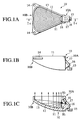
- Figs. 1A, 1B and 1C show the configuration of a small light-source module according to a first embodiment of the present invention, in which one LED 18 is small single-point light source is mounted as a light source to a module body 11.
- the module body 11 has the shape of a shallow shell, the inner bottom surface of which is a concave curved surface with a downward slant from the broadened end 10B to the narrowed end 10A of a fan shape, wherein a substantially fan-shaped reflective surface 12 is provided on the concave curved inner bottom surface so as to correspond to the shape of the module body 11.
- the LED 18, which emits a light H1 over a prescribed angular range toward the reflective surface 12, is provided on the narrowed end 10A of the module.
- An LED mounting part 16 is provided on the narrowed end 10A of the module body 11, the LED 18 being mounted thereto via an intervening bracket 17.
- the reference numeral 1 denotes an LED
- 2 is a reflective surface
- 3 is a line normal to the reflective surface 2
- 4 is a light axis
- 5 is a projected light region on the reflective surface 2 of the light from the LED 1
- ⁇ 1 is the tilt of the light axis 4 with respect to the normal line 3
- ⁇ 2 is the light-emitting angle of the LED 1
- L is the distance between the reflective surface 2 and the LED 1.
- the pattern of projected light will be round. If, however, the light axis is tilted (that is, if ⁇ 1 is not 0), the projected light region 5, as shown in the drawing, will be a shape that is close to that of fan, and the projected light surface area will increase.
- the reason that the module 10 is made fan-shaped is to achieve the best efficiency in extracting the reflected light over as wide a surface area as possible, by matching the outer contour shape of the reflective surface to the substantially fan-shaped projected light region 5.
- a multiple-step parabolic surface is formed as the reflective pattern 13, so that the light H1 from the LED 1 is reflected as parallel light H2.
- the reflective pattern 13 is integrally formed in the module body 11, and a metallic reflective film is formed thereonto, thereby forming the reflective surface 12 having the reflective pattern 13.
- Mounting tabs 14 and 15 for the broadened end 10B and the narrowed end 10A, respectively, are provided on the outer surface of the module body 11.
- a small light-source module 10 configured in this manner, it is possible to reflect the light from the LED 18, which has a limited light-emission angle, in a condition close to surface light emission, over the maximum surface area possible. Furthermore, it is possible to impart a degree of directionality, while broadening the light-emitting surface. By using a fan shape, it is possible to lay out a large number of the modules within a plane, thereby enabling production of light-source units having various light-emitting patterns.
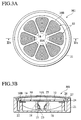
- Figs. 3A and 3B show a light-source unit M1 of the first embodiment fabricated using the above-noted module 10.
- the light-source unit M1 shown in Fig. 3A has a plurality of small light-source modules 10 arranged radially in a plane, with the narrowed ends 10A thereof having the LED 18 facing the inside (center) of the unit, and the opposite broadened ends 10B facing the outside (periphery) of the unit, this arrangement being integrally mounted to a round housing 21.
- bosses 22 and 23 are provided so as to protrude concentrically form the inner bottom part of the round receptacle housing 21, and the mounting tabs 14 and 15 are screwed to these bosses 22 and 23 so as to mount and arrange the modules 10 along the periphery.
- the reference numeral 25 denotes an inner panel supported by an annular step 24 formed along the inner periphery of the opening of the housing 21, and 26 denotes a spacer inserted between an outer lens 27 and the inner panel 25.
- modules 10 are possible to combine modules 10 in a variety of other forms.
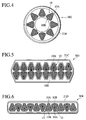
- a light-source unit M2 according to a second embodiment shown in Fig. 4 has an arrangement of modules 10 that is the opposite of that shown in Fig. 3A. That is, the plurality of modules 10 are arranged radially in a plane in a round housing 21B. with the narrowed ends 10A thereof facing the outside and the broadened ends 10B facing the inside, this arrangement being integrally mounted in the round housing 21B.
- this light-source unit M2 by adopting an orientation of fan-shaped modules 10 that is opposite that of the earlier-described arrangement, it is possible to produce a distinctive light emission design.
- modules 10 are arranged linearly in a vertical direction, with the narrowed ends 10A thereof facing in the same transverse direction, this arrangement being integrally mounted in a rectangular housing 21C.
- modules 10 are arranged linearly in a vertical direction, with the orientation of the narrowed ends 10A and the broadened ends 10B thereof alternating, this arrangement being integrally mounted in a rectangular housing 21D.
- the light-source units M3 and M4 use linear arrangements of the modules 10, thereby enabling production of surface light emission with a linearly arranged design.
- the light-source unit of Fig. 6 it is possible to achieve a dense layout of the modules 10, thereby enabling surface light emission with a high intensity.
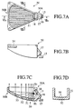
- Figs. 7A, 7B, 7C and 7D show a small light-source module 50 according to a fifth embodiment of the present invention.
- a module body 51 is formed by a transparent resin, and a reflective surface 52 is formed on the outer bottom surface of the module body 51, and a reflective pattern 53 is integrally formed on the outer bottom surface as a multiple-step parabolic surface.
- Small lenses 59 are formed in an array on the inner bottom surface opposite the LED 18.
- the module 50 by integrally forming a reflective surface 53 on the outer bottom surface of the module body 51, enables the provision of an array of small lenses 59 on the inner bottom surface. Therefore, light reaching the reflective surface 52 or light after reflection can be collected or dispersed by the small lenses 59, enabling the production of a condition that is closer to surface light emission. Additionally, because the reflective pattern 53 is on the outer surface, it provides the advantage of facilitating processing.
Landscapes
- Engineering & Computer Science (AREA)
- General Engineering & Computer Science (AREA)
- Physics & Mathematics (AREA)
- Mechanical Engineering (AREA)
- Microelectronics & Electronic Packaging (AREA)
- Optics & Photonics (AREA)
- Electromagnetism (AREA)
- Non-Portable Lighting Devices Or Systems Thereof (AREA)
- Led Device Packages (AREA)
Applications Claiming Priority (2)
| Application Number | Priority Date | Filing Date | Title |
|---|---|---|---|
| JP29997199A JP4010084B2 (ja) | 1999-10-21 | 1999-10-21 | 小型光源モジュール及び光源ユニット |
| JP29997199 | 1999-10-21 |
Publications (3)
| Publication Number | Publication Date |
|---|---|
| EP1094271A2 true EP1094271A2 (de) | 2001-04-25 |
| EP1094271A3 EP1094271A3 (de) | 2002-04-24 |
| EP1094271B1 EP1094271B1 (de) | 2007-09-05 |
Family
ID=17879196
Family Applications (1)
| Application Number | Title | Priority Date | Filing Date |
|---|---|---|---|
| EP00122801A Expired - Lifetime EP1094271B1 (de) | 1999-10-21 | 2000-10-19 | Kleines Lichtquellenmodul und Lichtquelleneinheit |
Country Status (5)
| Country | Link |
|---|---|
| US (1) | US6474852B1 (de) |
| EP (1) | EP1094271B1 (de) |
| JP (1) | JP4010084B2 (de) |
| KR (1) | KR20010049945A (de) |
| DE (1) | DE60036259T2 (de) |
Cited By (7)
| Publication number | Priority date | Publication date | Assignee | Title |
|---|---|---|---|---|
| WO2005036054A1 (en) * | 2003-10-10 | 2005-04-21 | Federal Signal Corporation | Light assembly |
| DE102004020154A1 (de) * | 2004-04-24 | 2005-11-10 | Hella Kgaa Hueck & Co. | Leuchte für Fahrzeuge |
| EP1411291A3 (de) * | 2002-10-18 | 2007-03-07 | Ichikoh Industries, Ltd. | Fahrzeugleuchte mit Leuchtdioden |
| GB2432653A (en) * | 2005-11-24 | 2007-05-30 | Gaiasphere Ltd | Torch with LED array combined into single beam |
| US8197110B2 (en) | 2003-10-10 | 2012-06-12 | Federal Signal Corporation | Light assembly incorporating reflective features |
| EP2562813A2 (de) * | 2011-08-23 | 2013-02-27 | Stanley Electric Co., Ltd. | LED Array geeignet zur Verringerung ungleichmäßiger Helligkeitsverteilung |
| EP3073179A1 (de) * | 2015-03-23 | 2016-09-28 | Siteco Beleuchtungstechnik GmbH | Led-modul mit schaufelförmigem reflektor sowie leuchte mit entsprechendem led-modul |
Families Citing this family (35)
| Publication number | Priority date | Publication date | Assignee | Title |
|---|---|---|---|---|
| JP3988393B2 (ja) * | 2001-01-26 | 2007-10-10 | スタンレー電気株式会社 | 赤外線投光器 |
| US6786618B2 (en) * | 2001-06-06 | 2004-09-07 | Goodrich Hella Aerospace Lighting Systems Gmbh | Light for an aircraft |
| US6840652B1 (en) * | 2001-07-31 | 2005-01-11 | Hi-Lite Safety Systems, L.C. | Lighting enhanced by magnified reflective surfaces |
| JP3986779B2 (ja) * | 2001-08-15 | 2007-10-03 | 株式会社小糸製作所 | 車両用灯具 |
| DE10260683B4 (de) * | 2001-12-26 | 2008-10-02 | Toyoda Gosei Co., Ltd. | LED-Leuchtvorrichtung |
| US6871993B2 (en) * | 2002-07-01 | 2005-03-29 | Accu-Sort Systems, Inc. | Integrating LED illumination system for machine vision systems |
| DE20219483U1 (de) * | 2002-12-16 | 2003-05-08 | FER Fahrzeugelektrik GmbH, 99817 Eisenach | Fahrzeugleuchte |
| US7387402B1 (en) | 2003-11-13 | 2008-06-17 | Lui Phillip Chun Wai | Multiple light LED flashlight |
| TW200532324A (en) * | 2004-03-23 | 2005-10-01 | Ace T Corp | Light source device |
| US20060013004A1 (en) | 2004-07-16 | 2006-01-19 | Charles Coushaine | LED sideward emitting lamp |
| DE102004063574A1 (de) * | 2004-12-30 | 2006-07-13 | Osram Opto Semiconductors Gmbh | Leuchtvorrichtung mit mehreren Halbleiterlichtquellen |
| US8591073B2 (en) * | 2005-03-03 | 2013-11-26 | Dialight Corporation | Beacon light with reflector and light emitting diodes |
| TWI294023B (en) * | 2006-03-17 | 2008-03-01 | Ind Tech Res Inst | Reflective illumination device |
| KR100783483B1 (ko) * | 2006-03-30 | 2007-12-07 | 양경호 | 엘이디 동영상 전광판용 엘이디 모듈 |
| JP4626618B2 (ja) * | 2007-01-12 | 2011-02-09 | 市光工業株式会社 | 車両用前照灯の灯具ユニット |
| JP2010528414A (ja) * | 2007-05-23 | 2010-08-19 | コーニンクレッカ フィリップス エレクトロニクス エヌ ヴィ | 自動車用照明器具 |
| JP4958702B2 (ja) * | 2007-09-19 | 2012-06-20 | セナーアンドバーンズ株式会社 | Led式灯具ユニット、灯台用led式灯具及びled式灯台 |
| JP5008547B2 (ja) | 2007-12-26 | 2012-08-22 | スタンレー電気株式会社 | 車両用灯具 |
| US7905639B2 (en) * | 2008-05-28 | 2011-03-15 | Osram Sylvania Inc. | Side-loaded light emitting diode module for automotive rear combination lamps |
| US7762701B2 (en) * | 2008-05-28 | 2010-07-27 | Osram Sylvania Inc. | Rear-loaded light emitting diode module for automotive rear combination lamps |
| US7762700B2 (en) * | 2008-05-28 | 2010-07-27 | Osram Sylvania Inc. | Rear-loaded light emitting diode module for automotive rear combination lamps |
| CN101614362B (zh) * | 2008-06-27 | 2012-06-13 | 富准精密工业(深圳)有限公司 | 发光二极管灯具 |
| US8113680B2 (en) * | 2009-05-05 | 2012-02-14 | Lightology, Llc | Light fixture with directed LED light |
| KR101114068B1 (ko) * | 2009-12-01 | 2012-02-22 | 기아자동차주식회사 | 차량용 헤드램프 |
| US8851707B2 (en) | 2010-06-15 | 2014-10-07 | Dialight Corporation | Highly collimating reflector lens optic and light emitting diodes |
| US20110310603A1 (en) * | 2010-06-16 | 2011-12-22 | Abl Ip Holding Llc | Light fixtures |
| EP2431656B1 (de) | 2010-09-16 | 2013-08-28 | LG Innotek Co., Ltd. | Beleuchtungsvorrichtung |
| CN201982994U (zh) | 2010-10-29 | 2011-09-21 | 通用电气公司 | 模组化照明灯具 |
| CN102767704A (zh) * | 2011-05-04 | 2012-11-07 | 鼎元光电科技股份有限公司 | 反打式灯具 |
| US8568000B2 (en) * | 2011-08-29 | 2013-10-29 | Tai-Her Yang | Annular-arranged lamp capable of backward projecting by concave sphere |
| JP2013246905A (ja) * | 2012-05-23 | 2013-12-09 | Koito Mfg Co Ltd | 車両用灯具 |
| US9726337B2 (en) * | 2014-08-27 | 2017-08-08 | R. W. Swarens Associates, Inc. | Light fixture for indirect asymmetric illumination with LEDs |
| DE102014117314A1 (de) * | 2014-11-26 | 2016-06-02 | Hella Kgaa Hueck & Co. | Beleuchtungsvorrichtung für Fahrzeuge |
| DE102015001695A1 (de) * | 2015-02-10 | 2016-08-11 | Audi Ag | Beleuchtungsvorrichtung für einen Scheinwerfer eines Kraftfahrzeugs sowie Verfahren zum Betreiben einer Beleuchtungsvorrichtung |
| CN109827144B (zh) * | 2018-10-23 | 2023-09-26 | 华域视觉科技(上海)有限公司 | 用于灯具同一功能区域实现两种均匀发光效果的光学系统 |
Family Cites Families (12)
| Publication number | Priority date | Publication date | Assignee | Title |
|---|---|---|---|---|
| US1811084A (en) * | 1928-03-30 | 1931-06-23 | Elvira Victoria Holmqvist | Lighting apparatus |
| US2636110A (en) * | 1950-04-17 | 1953-04-21 | Stein Alfred | Rainbow color device for fog penetrating lights |
| US4308573A (en) * | 1978-06-12 | 1981-12-29 | Esquire, Inc. | Lamp fixture including diffused low angle reflective surfaces |
| JPH0222891Y2 (de) * | 1987-04-02 | 1990-06-21 | ||
| US4929866A (en) | 1987-11-17 | 1990-05-29 | Mitsubishi Cable Industries, Ltd. | Light emitting diode lamp |
| DE3929955A1 (de) | 1989-09-08 | 1991-03-14 | Inotec Gmbh Ges Fuer Innovativ | Lichtstrahler |
| IT1281366B1 (it) * | 1995-09-27 | 1998-02-18 | Carello Spa | Dispositivo di illuminazione realizzabile con spessore ridotto, in particolare proiettore o fanale per veicoli |
| DE19638081A1 (de) * | 1996-09-19 | 1998-03-26 | Hella Kg Hueck & Co | Leuchte für Fahrzeuge |
| IT1292782B1 (it) | 1997-06-19 | 1999-02-11 | Fiat Ricerche | Fanale per autoveicoli. |
| DE19744715C1 (de) | 1997-10-10 | 1999-04-22 | Daimler Chrysler Ag | Beleuchtungsvorrichtung für das Heck eines Fahrzeuges |
| JP3173453B2 (ja) * | 1998-03-13 | 2001-06-04 | スタンレー電気株式会社 | 車両用信号灯具 |
| JP2960928B1 (ja) | 1998-07-24 | 1999-10-12 | スタンレー電気株式会社 | 車両用信号灯具 |
-
1999
- 1999-10-21 JP JP29997199A patent/JP4010084B2/ja not_active Expired - Fee Related
-
2000
- 2000-07-31 KR KR1020000044172A patent/KR20010049945A/ko not_active Ceased
- 2000-09-01 US US09/653,897 patent/US6474852B1/en not_active Expired - Fee Related
- 2000-10-19 DE DE60036259T patent/DE60036259T2/de not_active Expired - Lifetime
- 2000-10-19 EP EP00122801A patent/EP1094271B1/de not_active Expired - Lifetime
Cited By (12)
| Publication number | Priority date | Publication date | Assignee | Title |
|---|---|---|---|---|
| EP1411291A3 (de) * | 2002-10-18 | 2007-03-07 | Ichikoh Industries, Ltd. | Fahrzeugleuchte mit Leuchtdioden |
| US7281833B2 (en) | 2002-10-18 | 2007-10-16 | Ichikoh Industries, Ltd. | LED vehicle lamp including reflector with paraboloidal sections |
| EP2327925A1 (de) * | 2002-10-18 | 2011-06-01 | Ichikoh Industries, Ltd. | Fahrzeugleuchte mit Leuchtdioden |
| WO2005036054A1 (en) * | 2003-10-10 | 2005-04-21 | Federal Signal Corporation | Light assembly |
| US7578600B2 (en) | 2003-10-10 | 2009-08-25 | Federal Signal Corporation | LED light assembly with reflector having segmented curve section |
| US8197110B2 (en) | 2003-10-10 | 2012-06-12 | Federal Signal Corporation | Light assembly incorporating reflective features |
| US8206005B2 (en) | 2003-10-10 | 2012-06-26 | Federal Signal Corporation | Light assembly |
| DE102004020154A1 (de) * | 2004-04-24 | 2005-11-10 | Hella Kgaa Hueck & Co. | Leuchte für Fahrzeuge |
| DE102004020154B4 (de) * | 2004-04-24 | 2012-12-13 | Hella Kgaa Hueck & Co. | Leuchte für Fahrzeuge |
| GB2432653A (en) * | 2005-11-24 | 2007-05-30 | Gaiasphere Ltd | Torch with LED array combined into single beam |
| EP2562813A2 (de) * | 2011-08-23 | 2013-02-27 | Stanley Electric Co., Ltd. | LED Array geeignet zur Verringerung ungleichmäßiger Helligkeitsverteilung |
| EP3073179A1 (de) * | 2015-03-23 | 2016-09-28 | Siteco Beleuchtungstechnik GmbH | Led-modul mit schaufelförmigem reflektor sowie leuchte mit entsprechendem led-modul |
Also Published As
| Publication number | Publication date |
|---|---|
| KR20010049945A (ko) | 2001-06-15 |
| DE60036259T2 (de) | 2008-01-03 |
| EP1094271B1 (de) | 2007-09-05 |
| DE60036259D1 (de) | 2007-10-18 |
| EP1094271A3 (de) | 2002-04-24 |
| US6474852B1 (en) | 2002-11-05 |
| JP4010084B2 (ja) | 2007-11-21 |
| JP2001118408A (ja) | 2001-04-27 |
Similar Documents
| Publication | Publication Date | Title |
|---|---|---|
| EP1094271A2 (de) | Kleines Lichtquellenmodul und Lichtquelleneinheit | |
| US6367950B1 (en) | Vehicle lamp fixture and method of use | |
| US7635206B2 (en) | Light emitting diode lighting device having a lens connected to a hood | |
| US8475012B2 (en) | Lamp | |
| US7201503B2 (en) | Vehicular lamp including hemispherical translucent member with fan-shaped zones and lens elements | |
| JP2000040410A (ja) | 車両用信号灯具 | |
| US6758587B2 (en) | Light emitting diode license lamp with reflector | |
| US20040145910A1 (en) | Lighting assembly | |
| US20080278961A1 (en) | Hybrid Optics for L.E.D. Lamp | |
| JP2021180075A (ja) | 車両用灯具 | |
| JP2010140878A (ja) | 車両用灯具 | |
| JP2016195097A (ja) | 自動車用照明装置 | |
| EP1526330A2 (de) | Optisches System für Leuchtdioden | |
| US6752523B2 (en) | Vehicle lamp | |
| JP2011154912A (ja) | 車両用灯具 | |
| US20060268565A1 (en) | Led lighting device with light diffusing effect | |
| JP2004014197A (ja) | 車両用灯具 | |
| JP2010244833A (ja) | 車両用灯具 | |
| JP2011077002A (ja) | 照明器具 | |
| JP3394714B2 (ja) | 放光灯 | |
| CN211695553U (zh) | 一种冷柜 | |
| JP4138195B2 (ja) | 車両用灯具 | |
| TWM624361U (zh) | 側向反光杯系統 | |
| EP3561374B1 (de) | Fahrzeuglampe | |
| CN116940785A (zh) | 车辆用灯具 |
Legal Events
| Date | Code | Title | Description |
|---|---|---|---|
| PUAI | Public reference made under article 153(3) epc to a published international application that has entered the european phase |
Free format text: ORIGINAL CODE: 0009012 |
|
| 17P | Request for examination filed |
Effective date: 20001019 |
|
| AK | Designated contracting states |
Kind code of ref document: A2 Designated state(s): AT BE CH CY DE DK ES FI FR GB GR IE IT LI LU MC NL PT SE Kind code of ref document: A2 Designated state(s): DE FR GB |
|
| AX | Request for extension of the european patent |
Free format text: AL;LT;LV;MK;RO;SI |
|
| PUAL | Search report despatched |
Free format text: ORIGINAL CODE: 0009013 |
|
| AK | Designated contracting states |
Kind code of ref document: A3 Designated state(s): AT BE CH CY DE DK ES FI FR GB GR IE IT LI LU MC NL PT SE |
|
| AX | Request for extension of the european patent |
Free format text: AL;LT;LV;MK;RO;SI |
|
| AKX | Designation fees paid |
Free format text: DE FR GB |
|
| 17Q | First examination report despatched |
Effective date: 20060512 |
|
| GRAP | Despatch of communication of intention to grant a patent |
Free format text: ORIGINAL CODE: EPIDOSNIGR1 |
|
| RIC1 | Information provided on ipc code assigned before grant |
Ipc: F21Y 101/02 20060101ALI20070215BHEP Ipc: F21W 101/14 20060101AFI20070215BHEP |
|
| GRAS | Grant fee paid |
Free format text: ORIGINAL CODE: EPIDOSNIGR3 |
|
| GRAA | (expected) grant |
Free format text: ORIGINAL CODE: 0009210 |
|
| AK | Designated contracting states |
Kind code of ref document: B1 Designated state(s): DE FR GB |
|
| REG | Reference to a national code |
Ref country code: GB Ref legal event code: FG4D |
|
| REF | Corresponds to: |
Ref document number: 60036259 Country of ref document: DE Date of ref document: 20071018 Kind code of ref document: P |
|
| ET | Fr: translation filed | ||
| PLBE | No opposition filed within time limit |
Free format text: ORIGINAL CODE: 0009261 |
|
| STAA | Information on the status of an ep patent application or granted ep patent |
Free format text: STATUS: NO OPPOSITION FILED WITHIN TIME LIMIT |
|
| 26N | No opposition filed |
Effective date: 20080606 |
|
| PGFP | Annual fee paid to national office [announced via postgrant information from national office to epo] |
Ref country code: FR Payment date: 20101020 Year of fee payment: 11 |
|
| PGFP | Annual fee paid to national office [announced via postgrant information from national office to epo] |
Ref country code: DE Payment date: 20101013 Year of fee payment: 11 |
|
| PGFP | Annual fee paid to national office [announced via postgrant information from national office to epo] |
Ref country code: GB Payment date: 20101013 Year of fee payment: 11 |
|
| GBPC | Gb: european patent ceased through non-payment of renewal fee |
Effective date: 20111019 |
|
| REG | Reference to a national code |
Ref country code: FR Ref legal event code: ST Effective date: 20120629 |
|
| PG25 | Lapsed in a contracting state [announced via postgrant information from national office to epo] |
Ref country code: DE Free format text: LAPSE BECAUSE OF NON-PAYMENT OF DUE FEES Effective date: 20120501 |
|
| REG | Reference to a national code |
Ref country code: DE Ref legal event code: R119 Ref document number: 60036259 Country of ref document: DE Effective date: 20120501 |
|
| PG25 | Lapsed in a contracting state [announced via postgrant information from national office to epo] |
Ref country code: GB Free format text: LAPSE BECAUSE OF NON-PAYMENT OF DUE FEES Effective date: 20111019 Ref country code: FR Free format text: LAPSE BECAUSE OF NON-PAYMENT OF DUE FEES Effective date: 20111102 |