EP1091066A2 - Drehband für Türen oder Fenster - Google Patents
Drehband für Türen oder Fenster Download PDFInfo
- Publication number
- EP1091066A2 EP1091066A2 EP00104918A EP00104918A EP1091066A2 EP 1091066 A2 EP1091066 A2 EP 1091066A2 EP 00104918 A EP00104918 A EP 00104918A EP 00104918 A EP00104918 A EP 00104918A EP 1091066 A2 EP1091066 A2 EP 1091066A2
- Authority
- EP
- European Patent Office
- Prior art keywords
- hinge
- wing
- slide plate
- doors
- windows according
- Prior art date
- Legal status (The legal status is an assumption and is not a legal conclusion. Google has not performed a legal analysis and makes no representation as to the accuracy of the status listed.)
- Granted
Links
Images




Classifications
-
- E—FIXED CONSTRUCTIONS
- E05—LOCKS; KEYS; WINDOW OR DOOR FITTINGS; SAFES
- E05D—HINGES OR SUSPENSION DEVICES FOR DOORS, WINDOWS OR WINGS
- E05D5/00—Construction of single parts, e.g. the parts for attachment
- E05D5/10—Pins, sockets or sleeves; Removable pins
- E05D5/12—Securing pins in sockets, movably or not
- E05D5/128—Securing pins in sockets, movably or not the pin having a recess or through-hole engaged by a securing member
-
- E—FIXED CONSTRUCTIONS
- E05—LOCKS; KEYS; WINDOW OR DOOR FITTINGS; SAFES
- E05D—HINGES OR SUSPENSION DEVICES FOR DOORS, WINDOWS OR WINGS
- E05D11/00—Additional features or accessories of hinges
- E05D11/0054—Covers, e.g. for protection
-
- E—FIXED CONSTRUCTIONS
- E05—LOCKS; KEYS; WINDOW OR DOOR FITTINGS; SAFES
- E05D—HINGES OR SUSPENSION DEVICES FOR DOORS, WINDOWS OR WINGS
- E05D7/00—Hinges or pivots of special construction
- E05D7/04—Hinges adjustable relative to the wing or the frame
- E05D7/0415—Hinges adjustable relative to the wing or the frame with adjusting drive means
- E05D7/0423—Screw-and-nut mechanisms
-
- E—FIXED CONSTRUCTIONS
- E05—LOCKS; KEYS; WINDOW OR DOOR FITTINGS; SAFES
- E05D—HINGES OR SUSPENSION DEVICES FOR DOORS, WINDOWS OR WINGS
- E05D7/00—Hinges or pivots of special construction
- E05D7/10—Hinges or pivots of special construction to allow easy separation or connection of the parts at the hinge axis
- E05D7/1005—Hinges or pivots of special construction to allow easy separation or connection of the parts at the hinge axis by axially moving free pins, balls or sockets
-
- E—FIXED CONSTRUCTIONS
- E05—LOCKS; KEYS; WINDOW OR DOOR FITTINGS; SAFES
- E05D—HINGES OR SUSPENSION DEVICES FOR DOORS, WINDOWS OR WINGS
- E05D7/00—Hinges or pivots of special construction
- E05D7/10—Hinges or pivots of special construction to allow easy separation or connection of the parts at the hinge axis
- E05D7/1044—Hinges or pivots of special construction to allow easy separation or connection of the parts at the hinge axis in an axial direction
-
- E—FIXED CONSTRUCTIONS
- E05—LOCKS; KEYS; WINDOW OR DOOR FITTINGS; SAFES
- E05D—HINGES OR SUSPENSION DEVICES FOR DOORS, WINDOWS OR WINGS
- E05D11/00—Additional features or accessories of hinges
- E05D11/0018—Anti-tamper devices
-
- E—FIXED CONSTRUCTIONS
- E05—LOCKS; KEYS; WINDOW OR DOOR FITTINGS; SAFES
- E05D—HINGES OR SUSPENSION DEVICES FOR DOORS, WINDOWS OR WINGS
- E05D3/00—Hinges with pins
- E05D3/02—Hinges with pins with one pin
- E05D2003/025—Hinges with pins with one pin having three knuckles
-
- E—FIXED CONSTRUCTIONS
- E05—LOCKS; KEYS; WINDOW OR DOOR FITTINGS; SAFES
- E05D—HINGES OR SUSPENSION DEVICES FOR DOORS, WINDOWS OR WINGS
- E05D5/00—Construction of single parts, e.g. the parts for attachment
- E05D5/10—Pins, sockets or sleeves; Removable pins
- E05D2005/102—Pins
-
- E—FIXED CONSTRUCTIONS
- E05—LOCKS; KEYS; WINDOW OR DOOR FITTINGS; SAFES
- E05D—HINGES OR SUSPENSION DEVICES FOR DOORS, WINDOWS OR WINGS
- E05D7/00—Hinges or pivots of special construction
- E05D7/10—Hinges or pivots of special construction to allow easy separation or connection of the parts at the hinge axis
- E05D7/1005—Hinges or pivots of special construction to allow easy separation or connection of the parts at the hinge axis by axially moving free pins, balls or sockets
- E05D2007/1027—Hinges or pivots of special construction to allow easy separation or connection of the parts at the hinge axis by axially moving free pins, balls or sockets by axially moving free pins
-
- E—FIXED CONSTRUCTIONS
- E05—LOCKS; KEYS; WINDOW OR DOOR FITTINGS; SAFES
- E05D—HINGES OR SUSPENSION DEVICES FOR DOORS, WINDOWS OR WINGS
- E05D5/00—Construction of single parts, e.g. the parts for attachment
- E05D5/10—Pins, sockets or sleeves; Removable pins
- E05D5/14—Construction of sockets or sleeves
-
- E—FIXED CONSTRUCTIONS
- E05—LOCKS; KEYS; WINDOW OR DOOR FITTINGS; SAFES
- E05D—HINGES OR SUSPENSION DEVICES FOR DOORS, WINDOWS OR WINGS
- E05D5/00—Construction of single parts, e.g. the parts for attachment
- E05D5/10—Pins, sockets or sleeves; Removable pins
- E05D5/14—Construction of sockets or sleeves
- E05D5/16—Construction of sockets or sleeves to be secured without special attachment parts on the socket or sleeve
-
- E—FIXED CONSTRUCTIONS
- E05—LOCKS; KEYS; WINDOW OR DOOR FITTINGS; SAFES
- E05D—HINGES OR SUSPENSION DEVICES FOR DOORS, WINDOWS OR WINGS
- E05D7/00—Hinges or pivots of special construction
- E05D7/02—Hinges or pivots of special construction for use on the right-hand as well as the left-hand side; Convertible right-hand or left-hand hinges
-
- E—FIXED CONSTRUCTIONS
- E05—LOCKS; KEYS; WINDOW OR DOOR FITTINGS; SAFES
- E05Y—INDEXING SCHEME ASSOCIATED WITH SUBCLASSES E05D AND E05F, RELATING TO CONSTRUCTION ELEMENTS, ELECTRIC CONTROL, POWER SUPPLY, POWER SIGNAL OR TRANSMISSION, USER INTERFACES, MOUNTING OR COUPLING, DETAILS, ACCESSORIES, AUXILIARY OPERATIONS NOT OTHERWISE PROVIDED FOR, APPLICATION THEREOF
- E05Y2800/00—Details, accessories and auxiliary operations not otherwise provided for
-
- E—FIXED CONSTRUCTIONS
- E05—LOCKS; KEYS; WINDOW OR DOOR FITTINGS; SAFES
- E05Y—INDEXING SCHEME ASSOCIATED WITH SUBCLASSES E05D AND E05F, RELATING TO CONSTRUCTION ELEMENTS, ELECTRIC CONTROL, POWER SUPPLY, POWER SIGNAL OR TRANSMISSION, USER INTERFACES, MOUNTING OR COUPLING, DETAILS, ACCESSORIES, AUXILIARY OPERATIONS NOT OTHERWISE PROVIDED FOR, APPLICATION THEREOF
- E05Y2800/00—Details, accessories and auxiliary operations not otherwise provided for
- E05Y2800/26—Form or shape
-
- E—FIXED CONSTRUCTIONS
- E05—LOCKS; KEYS; WINDOW OR DOOR FITTINGS; SAFES
- E05Y—INDEXING SCHEME ASSOCIATED WITH SUBCLASSES E05D AND E05F, RELATING TO CONSTRUCTION ELEMENTS, ELECTRIC CONTROL, POWER SUPPLY, POWER SIGNAL OR TRANSMISSION, USER INTERFACES, MOUNTING OR COUPLING, DETAILS, ACCESSORIES, AUXILIARY OPERATIONS NOT OTHERWISE PROVIDED FOR, APPLICATION THEREOF
- E05Y2900/00—Application of doors, windows, wings or fittings thereof
- E05Y2900/10—Application of doors, windows, wings or fittings thereof for buildings or parts thereof
- E05Y2900/13—Type of wing
- E05Y2900/132—Doors
-
- E—FIXED CONSTRUCTIONS
- E05—LOCKS; KEYS; WINDOW OR DOOR FITTINGS; SAFES
- E05Y—INDEXING SCHEME ASSOCIATED WITH SUBCLASSES E05D AND E05F, RELATING TO CONSTRUCTION ELEMENTS, ELECTRIC CONTROL, POWER SUPPLY, POWER SIGNAL OR TRANSMISSION, USER INTERFACES, MOUNTING OR COUPLING, DETAILS, ACCESSORIES, AUXILIARY OPERATIONS NOT OTHERWISE PROVIDED FOR, APPLICATION THEREOF
- E05Y2900/00—Application of doors, windows, wings or fittings thereof
- E05Y2900/10—Application of doors, windows, wings or fittings thereof for buildings or parts thereof
- E05Y2900/13—Type of wing
- E05Y2900/148—Windows
Definitions
- the invention relates to a hinge for doors or window, with the characteristics of the generic term of Claim 1.
- Rotary tapes serve as connecting elements between the Sash and the frame. They allow the swiveling of the Wing on the frame. They must also be suitable for this be to adjust the door leaf in relation to the frame can.
- Conventional and well-known tapes with the features mentioned are designed so that the horizontal sash adjusters are integrated in the wing hinge, the vertical
- height adjustment devices allowing wing adjustment in the frame band. This is disadvantageous in several ways.
- the wing hinge is related to the frame hinge with a height adjustment corresponding to the adjustment height shifted. There are gaps, the height of the adjustment are correspondingly different sizes. Consequently is a uniform appearance of the lathe at the possible different height positions not possible. It is particularly necessary for larger height adjustments to cover the gap, which requires additional design effort means.
- the hinge axis with a height adjustment of the wing hinge pushed up out of the frame hinge This will create the overlap between the joint axis and the frame band lower.
- the hold of the joint axis in the frame band is reduced accordingly.
- Another The peculiarity of the well-known hinge is that it is too Adjustment purposes has a spindle slide, the pins and has screws that engage the wing, but to do so push a tab of the wing hinge so that the latter be clamped to the wing with the spindle slide can.
- the pins and screws are not over their entire length resulted in a tipping of the unguided Screws and pins especially for higher or shock-like ones Can result in stresses, causing the wing hinge leaves its defined position and tilts accordingly.
- the invention is based on the object a hinge with the features mentioned above to improve that the wing hinge when adjusting the Wing serving adjustment processes its relative position not changed to the frame hinge and a secure mounting of the Wing hinge on the wing remains guaranteed.
- the above object is achieved in that the Height adjustment device together with the side adjustment device is integrated into the wing hinge.
- a conventional hinge axis is used come and the frame strap can also be in conventional Be trained.
- a relative height adjustment between Sash hinge and frame hinge are avoided. Between the two there is no gap that should be covered.
- the hinge axis is not pushed up out of the frame hinge, so that there is a corresponding destabilization of the Turntable could result.
- the height adjustment device can be found in the wing hinge and integrated the side adjustment device that there is an advantageous construction, basically also with regard to avoiding one Tilting the wing hinge on the wing.
- a particularly advantageous design of the rotating belt is achieved in that the height and side adjustment devices are integrated by means of a cross slide that with a first slide plate horizontally and with a second carriage plate is vertically adjustable.
- a cross slide is basically able to all points one Control level with one of the sled plates.
- the rotating belt can all positions of the Wing in the wing plane by influencing the Height and / or on the side adjustment device in the frame the structurally specified setting limits can be reached.
- the slide plates are adjustable either horizontally or vertically. It it is also possible to make them horizontal and vertical to be arranged at an angle. It is also not mandatory that the angle between the adjustment directions of the two Sled plates is a right one.
- Reasons for a departure the adjustment directions from the horizontal and / or from the Vertical can be seen, for example, in that the Wing has a preferably oblique tilting direction if possible mastered with a single adjustment device shall be.
- the hinge so that the first slide plate or the second slide plate sunk in a recess of the wing hinge between them and the second carriage plate and the first carriage plate, respectively is adjustable.
- This way basically achieved that both slide plates on one side of the wing hinge can be arranged in the same recess.
- the second slide plate forms one base plate firmly attached to the wing and immovable on it, with all wing movements at first Carriage plate and transfer from this to the wing hinge can be.
- the relative displacement between the two Sled plates ensure the relative displaceability of the wing hinge with respect to all points of the adjustment level the cross slide.
- a further development of the rotating belt is expedient in that that the second carriage plate on the first carriage plate horizontally unadjustable, but vertically limited is adjustable or that the first slide plate on the second slide plate adjustable horizontally, however is vertically unadjustable.
- the second carriage plate on the first carriage plate horizontally unadjustable, but vertically limited is adjustable or that the first slide plate on the second slide plate adjustable horizontally, however is vertically unadjustable.
- the above-described positive connection of the rotating belt can be achieved in particular in that the first and second slide plates with vertical grooves and Ribs are vertically adjustable engaged or that the first and second slide plates with horizontal grooves and ribs are engaged horizontally adjustable.
- the second carriage plate within the recess receiving the first slide plate arranged and their vertical adjustability from this Recess is limited. This is particularly advantageous when the first and second sled plates are on the same Side of the wing hinge are arranged.
- the second sled plate with one wing-side outer wall of the wing hinge is aligned. she is then complete together with the first slide plate arranged within the recess of the wing hinge. It results a tight contact of the second slide plate The wing and the wing hinge are accordingly close to the wing on.
- the hinge For an advantageous attachment of the hinge to the wing
- it can be designed so that the second sled plate practically one by the height of the wing hinge has a certain height, minus the vertical Adjustment height and the formation of the second slide plate receiving recess required wall thicknesses of the Wing band, and that the second carriage plate one through the width of the wing hinge has a certain width, minus the horizontal adjustment width and that for training of the recess accommodating the second slide plate Wall thickness of the wing hinge.
- this will a second sled plate with a comparatively large size Area reached.
- a large sled plate is advantageous because the large sled surface is large Pad on the wing results in a corresponding secure attachment can be made.
- the second slide plate or a wing-side clamping plate near corners and / or edges in one piece or rigidly attached, in the Has wing engaging support pins and / or claws.
- the support pins and / or claws form an immediate one Connection with the wing, i.e. without distance between the second slide plate and the wing, so that if the production is sufficiently precise, the second tilts Sled plate or the wing hinge on the wing excluded can be.
- the hinge can be designed so that between the first / second slide plate and the wing hinge a horizontal / vertical adjustment screw and between the second / first and first / second slide plate one vertical adjustment screw is arranged that screw heads the adjustment screws each have a through opening of the sash hinge are adjacent that the horizontal adjustment screw with its screw head in the wing hinge / the first slide plate engages non-adjustable and on a screw shaft one engaging positively in the first slide plate Has adjusting nut, and that the vertical adjusting screw with her screw head in the first slide plate / that Sash hinge interlocks as well as on one Screw shaft with a positive fit in the second slide plate engaging adjusting nut.
- the hinge can be developed so that the wing hinge has a clamping plate with which it is shared with to fix the cross slide on the wing is.
- the clamping plate forms both the fastener for the wing hinge, as well as for its cross slide. Fixing the clamping plate results in one on the sash altogether unadjustable fixed adjustment device. With a single clamping plate, all conceivable Adjustment directions of both the side and the height adjustment device blocked.
- a special training of the rotating belt stands out characterized in that the cross slide facing away from the wing or wing a guide wall of the wing hinge and the clamping plate on the side of the guide wall facing away from the cross slide are arranged.
- the Guide wall in any position of the vertical cross table Location of all the adjustment or clamping serving plates.
- the plates can be perpendicular to the guide wall and thus do not adjust to the sash level.
- the Clamping plate can be made large enough to the required Transfer clamping forces to the guide wall can.
- the second alternative is based on the wing hinge is over the clamping plate on the wing So it is relatively close to it. It follows an advantageous solid constructive bond between the Wing hinge, the clamping plate and the wing, which by comparative small wall thicknesses can be excellent.
- Another training of the rotating belt with regard to his Clamping plate is characterized in that the clamping plate in a wing-facing / wing-facing recess of the Wing hinge is arranged and flush with the outer surface lies or protrudes slightly. Accordingly, the Clamping plate housed inside the wing hinge and it results in a practical and handsome design of the Rotary conveyor.
- the second alternative described above supports a contact structure in the area between the wing hinge and the wing. The slight protrusion of the clamping plate causes the wing hinge not to be attached competes with the clamping plate, i.e. a predetermined one Attachment can be guaranteed.
- the hinge can also be designed so that the clamping plate and the second slide plate are aligned, Fastening screws have through holes, that the first slide plate allow their vertical adjustments Has vertical slots, and that the guide wall of the Wing hinge with vertical and horizontal hinge movements related of the recesses allowing the fastening screws is provided.
- the wing hinge with the Clamping plate can be reliably clamped on the wing, although the Clamping plate facing away from the wing is arranged on the wing hinge.
- the construction with the clamping plate be designed so that adjustments of the wing hinge are possible without fastening means of the clamping plate to have to solve.
- the rotating belt is designed so that the clamping plate with guide pins through recesses of the wing hinge and vertical slots of the first slide plate engages in the second slide plate and if necessary is firmly connected to it.
- the fixed mobility of both parts is the relative mobility of the first slide plate and the guide wall or the Axial bore bearing area of the sash guaranteed.
- a particularly advantageous embodiment of the rotating belt is reached when a sled plate in a vertical or horizontal recess of the wing hinge or its guide wall is vertically or horizontally limited adjustable.
- the relevant guide of the slide plate can be used as the main guide of the carriage on the wing hinge. This Main tour can meet the stability requirements of the Wing hinge and its clamping as well as the accuracy of guidance be adjusted. As a result, the training of the Wing bands relieved in other areas. For example lower tolerances can be accepted there.
- a special training in the aforementioned sense is characterized in that the second slide plate with a Guide bar in the vertical recess and / or with guide cams engages in vertical guide channels of the guide wall, and that the guide bar, if necessary, over horizontal Driving grooves and ribs with the wing-side clamping plate is in vertical entrainment.
- the intervention of the second slide plate into the vertical recess, that the wing hinge comparatively compact perpendicular to the wing can be trained.
- There is also the possibility namely with a correspondingly wide reach the guide bar in the area of the clamping plate, between to train both of them to be stable, which is not only the necessary adjustment of the clamping plate is guaranteed, but also unproblematic form of leadership of grooves and ribs allowed to use.
- Guide cams in vertical guide channels of the guide wall will further stabilize the belt structure reached.
- the hinge it is preferable to design the hinge so that the first slide plate recesses in the guide wall has sweeping support projections on the clamping plate are supported and, if necessary, fastening screws have leading through holes. Supporting the first carriage plate on the clamping plate causes last are pressed against the wings with the support projections can. Another part in between, such as the second sled plate, which is used to fix the entire wing hinge should be clamped, is in the area of mounting screws unavailable. There is one space-saving design if the support projections are through holes have through which the fastening screws for Attachment to the wing can be inserted.
- the hinge can be given a handsome appearance if the wing hinge is an unadjustable on the visible side Clamping plate covering the first slide plate having.
- the cover cap can also be used for this be to cover the wing band overall, so that Passage openings of the wing hinge for the adjustment screws, for fastening screws of the clamping plate and others Parts are inaccessible that affect the function of the rotating belt could affect.
- axle mounting hole of the sash accessible from the side, but from the Cover cap is covered.
- the accessibility of the axle mounting hole allows the hinge axis or an existing one additional axle pin after removing the cover cap drive out, thereby the articulated connection between the wing hinge and the hinge.
- the invention further relates to Hinge for doors or windows, with one on a wing wing hinge to be attached, with an articulated axis a frame hinge to be fastened to a frame is.
- the articulation axis is usually used in such rotating belts as long as the entire rotating band is high.
- the hinge axis extends practically over the total height of the sash. That has two-part hinges the consequence that the wing the height of the wing hinge must be raised accordingly so that the wing hinge from the joint axis can be taken. Often, however such a height is not available because of the upper ligament is arranged close under a building ceiling.
- a rotating belt to train with the aforementioned features so that it in particular can then be used when it is just below a building ceiling is to be applied.
- This task will solved in that the hinge axis an engagement length in has the wing hinge, which is shorter than its axis receiving bore is in the upper free bore end on the frame band releasably attached axle pin is used. At disassembly of the hinge from the frame is first the axle pin released. Then the door wing only needs accordingly the engagement length of the joint axis to be raised to be able to remove the sash hinge from the frame hinge laterally.
- the shorter engagement length of the joint axis in the Sash hinge ensures the stability of the hinge, namely due to the bipartite nature of the whole Joint axis and the axis pin formed the axis of rotation of the rotating belt.
- the wing can in particular be hooked in as usual and be posted. It is not necessary when hanging and unhooking of the door leaf on a special construction of the hinge to watch out for. A subsequent installation of the axle pin does not affect the hanging of the door leaf.
- the hinge it is advantageous to design the hinge so that the Wing hinge one between the hinge axis and the axle pin has axis stop engaging in the axle mounting bore.
- the axle stop prevents striking both the hinge axis, as well as the axis pin.
- the hinge is designed so that the hinge axis and the axle pin have an annular groove near the axle stop, into which one holding pin detachably fastened in the wing hinge tangentially intervenes.
- the retaining pins sit positively in the ring grooves the hinge axis and the axis pin and thus secure their axial position in the wing hinge, as well as relative to Frame hinge.
- the rotary band can be designed in a special way be that the axle pin of a two-part hinge with a Cross bracket is held against horizontal loads, which is releasably attached to the frame hinge if necessary.
- the Cross plate transfers loads acting on the axle pin.
- the cross flap can be detachably attached to the frame hinge.
- a two-part axle training can be done with one Advantageously use the hinge so that the axle pin one three-part hinge and its hinge axis of the same design and with mutually facing ring grooves in the axle mounting hole of the wing hinge are arranged.
- This Design of the rotating belt is due to the number of parts the equal training of the axis pin and the joint axis reduced.
- the structure of the rotating belt can also be used for this be coordinated.
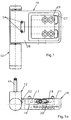
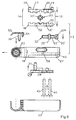
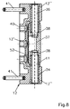
- the turrets shown in the figures each exist from a wing hinge 10, which with a frame hinge 12th is articulated via a hinge axis 11.
- the wing band is in a conventional and therefore not shown manner attached to a wing, e.g. on the frame of a door leaf.
- the frame band 12 is also conventional and therefore not shown attached to a frame, e.g. on a frame of a door.
- These fortifications serve the mounting holes shown in Fig.2,8 40 and mounting screws, not shown.
- the Mounting holes 40 are located in a mounting leg 12 ', to which the two-part hinge of the Fig.2 below a bearing eye 12 '' connects while the in Fig.
- each axle receiving bushes 34 for receiving the joint axis 11 or an axle pin 36.
- the axle mounting bushes 34 are made of friction-reducing plastic and are inserted in the bearing eyes 12 '' against rotation.
- the conclusion the bearing eyes 12 '' are made by means of caps 42, to prevent contamination of the storage and a handsome To reach the outside of the rotating belt in this area.
- the wing hinge 10 is substantially plate-shaped and provided with an axle receiving bore 10 ', which extends over the entire height of the wing hinge 10 extends.
- the Axle mounting hole 10 ' is a combined side / height adjustment device 13.14 available.
- the adjustment devices 13 and 14 are accommodated in recesses 18, 27 which form a guide wall 26 between them. In the guide wall 26 are recesses designed according to FIG 30 for reaching through components of the adjustment devices 13.14.
- the recesses 18, 27 are essentially rectangular, but with rounded corners and edges, in particular Surfaces arranged conically perpendicular to the guide wall 26 are designed to be opening and functioning of the components of the adjustment devices 13, 14 in the To facilitate recesses 18, 27 and in particular a clamping to prevent.
- the cross slide 15 has a first slide plate 16 and a second carriage plate 17.
- the carriage plate 17 is transverse to the hinge axis in the recess 18 of the wing hinge 10 movable and lies close to the guide wall 26. there the first slide plate 16 can only perform horizontal movements execute, but not vertical, parallel to the hinge axis 11 directional movements.
- a second slide plate 17 is with the first via vertical grooves 19 and ribs 20 in a form-fitting manner Intervention. The form fit is such that the second slide plate 17 on the first slide plate 16 can only move vertically, but not horizontally. Since the first Carriage plate 16 does not have its own vertical movement is possible, the second slide plate 17 is the only one Means for vertical movements of the cross slide and thus of the wing hinge.
- Both slide plates 16, 17 are dimensioned so thick that they are to be accommodated together in the recess 18 and the second slide plate 17 with the wing side Outer wall 21 of the wing hinge 10 is aligned.
- the second sled plate 17 has projecting support pins 24 which are arranged at corners and edges of the slide plate 17. These support pins engage in appropriately sized Holes of the casement so that the second carriage plate 17 sits immovably in the plane of the wing.
- the support pins 24 are as far apart from each other as possible away. For example, there is a single support pin in the Arranged in the middle on a vertical edge of the slide plate 17, while their other vertical edge at the corners has two support pins 24.
- Adjustment means are used to actuate the adjusting device 13, 14 needed. Adjusting screws 22, 23 are used for this. on the screw shafts are adjusting nuts. For example has a screw shaft 22 '' an adjusting nut 22 '' 'on. The screw head 22 'is in a recess 43 of the guide wall 26 axially displaceable, but rotatable arranged. On the other hand, the screw head 22 ' horizontal adjustment of the first slide plate 16 Not. Such adjustment is achieved in that the Adjustment screw 22 with a through opening 24 inserted and into an inner polygonal recess 22 '' ''' engaging tool, not shown, is rotated.
- the second slide plate 17 adjusted relative to the first slide plate 16 can be.
- Adjusting screw 23 available, the screw head 23 'into a recess in the first slide plate 16 engages axially non-adjustable, without adjusting the slide plate 16 because of a spacious provided in this Hinder recess.
- the clamping plate 25 is with two guide pins 31 arranged vertically one above the other provided which the recesses 30 of the guide wall 26th reach through, as well as vertical slots 32 of the first slide plate 16.
- the guide pins 31 can consequently in engage holes, not shown, in the second slide plate 17, so that the clamping plate 25 always all movements this slide plate performs. Stabilize the guide pins 31 the connection of the three plates 25, 16, 17 on the guide wall 26 and can be firmly connected to the plate 17. In this way it is possible to pre-assemble the cross slide to be delivered with the wing hinge.
- axle bushings 47 shown in Figure 5. They are made of plastic and cause a reduction the bearing friction.
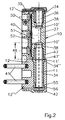
- the storage of the wing hinge 10 on the frame hinge 12 serve a hinge axis 11 and an axle pin 36 Hinge axis 11 is 48 in according to FIG. 2 with an engagement length the axle mounting hole 10 'used, which is much smaller is, as their total length, that of the height of the wing hinge 10 corresponds.
- the wing hinge bushing is accordingly short 47, over the collar 47 'of which the wing hinge 10 is supported on a collar 34 '' of the axle mounting bush 34.
- This support is also carried out on a ring collar 11 'of the hinge axis 11, which is present, around a prevent axial penetration of the joint axis.
- Such one Axial penetration upwards is also prevented through an axle stop 37 which is in the axle receiving bore 10 'engages.
- the axle stop 37 supports the hinge axis 11 as well as an axle pin 36, which is in the top of the Axle mounting hole 10 'sits.
- the axle pin 36 is radial with a cross plate 39 held.
- the cross plate 39 is on the frame strap 12 attached.
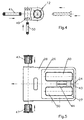
- 3 shows the tab 39 with two mutually parallel Fastening projections 39 'which are used when assembling the Cross plate 39 with the frame band 12 in the shown in Figure 4 Insert slots 49 are inserted.
- a Cross pin 50 becomes the cross plate 39 against axial disassembly secured and there is a cover by a protective cap 42 made. It is possible to remove the axle pin 36 the wing hinge 10 to remove the disassembly facilitate. For this purpose, after removing the protective cap 42 first the cross pin 50 is removed, then the cross tab 39 removed from the frame hinge and the axle pin 36 expelled upwards.
- the expulsion takes place with a Tool that laterally into the axle mounting hole 10 ' an opening 51 of the frame band 10 is inserted.
- This Opening 51 is only accessible if a cover cap 33 is used beforehand is removed, with which the visible side of the Wing band 10 is covered.
- the opening 51 is covered by a cover 52, the the outer circumference of the wing hinge in the area of Axle mounting hole 10 'is adapted and about the entire wing hinge height.
- Your assembly on the wing hinge 10 is done with a retaining pin 39, which is in a transverse bore 53 of the wing hinge 10 is inserted so that it is at the same time engages tangentially in an annular groove 38 of the joint axis 11.
- There is a second retaining pin 39 which corresponds to this tangentially into an annular groove 38 of the axle pin 36 intervenes.
- This results in a two-point bracket for the cover 52 which also has two actuating pins 54, which are accessible in front of the flight belt 10, to dismantle the cover 52 or the retaining pins 39.
- a three-part hinge 10 is shown, which is formed in the lower area as well the hinge 10 of Figures 1 to 2.
- the top is another Bearing eye 12 '' in which an axle pin 36 for radial Bracket of the hinge 10 is present.
- the axle pin is designed in the same way as the hinge axis 11, only this one arranged in opposite directions.
- the three-part hinge is accordingly symmetrical.
- the axle mounting bush 34 a bearing eye 12 '' with an eccentric mounting hole 34 'may be provided.
- Fig. 9 shows such an axle mounting bush 34, in which the axis receiving bore 34 'from a contact surface 12 '' 'of the frame hinge 12 stored away on the sash is arranged. The extent of the shift results from the distance between the two center lines parallel in FIG. 9, from which the lower the center line of the axle mounting hole 34 ' is while the top is the center line of the bushing bore 57 is.
- the axle mounting bush 34 becomes 90 degrees adjusted, both center lines coincide, so that the Sash hinge 10 and thus the sash shifted towards the frame is.
- the contact pressure is increased accordingly.
- the maximal Pressure adjustment results from a rotation of the Axle mounting bush 34 by 180 degrees.
- the rotating setting Position of the axle receiving bushing 34 can be conventional Be secured way, for example by the cover 42 with projections, not shown, both in axially parallel slots 55 of the axle receiving bush 34 engage, as well as in slots 56 of the bearing eye 12 ''.
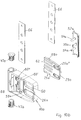
- FIG. 10a, b, 11 are details of another Embodiment of a hinge shown according to the invention.
- the parts of this hinge shown are the same or have comparable functions to those described above Embodiments, they are with corresponding Provide reference numerals to which a lower case a has been applied.
- the training and function apply to these parts, to the extent they have been described above.
- This is especially true for the frame hinge 12a shown in Fig. 10a, b in comparison to the frame hinge of Fig. 9.
- Supplementary plates are 66 depicted the bridging of distances serve between the frame and the frame band 12a and with the holes shown to push through e.g. of fastening screws are provided.
- the wing hinge 10a corresponds in its basic training the wing hinge 10, accordingly has a clamping plate 25a, a height adjustment device 14a, a side adjustment device 13a, each combined with a cross slide 15a. There is a horizontal adjustment screw 22a like a vertical adjusting screw 23a. These are with the Cross slide 15a combined in the manner described.
- a decisive deviation of the wing hinge 10a is that the cross slide 15 averted wings in a recess 18a of the wing hinge 10a is arranged while the Clamping plate 25a in a recess 27a facing the wing of the wing hinge 10a.
- the wing hinge 10a is especially designed in the area of the second slide plate 17a in that the latter has a vertical guide bar 61 which fits into a vertical recess 60 'of the guide wall 26a.
- Parallel to the guide bar 61 are two guide cams 61 ' arranged one above the other.
- the cams 61 ' are longer than they are wide and extend towards one another from the horizontal edges of the second slide plate 17a. They engage in the vertical guide grooves 60 ′′ shown in the illustration of the wing hinge 10a or the guide wall 26a, which are longer in accordance with the vertical adjustability of the second slide plate 17a.
- the guide cams 61 ' and the guide grooves 60 '' interacting therewith do not hinder the vertical adjustability of the second slide plate 17a, but prevent horizontal adjustment movements or tilting adjustments, so that the belt structure is stabilized accordingly.
- the second slide plate 17a cannot be adjusted horizontally, but can be adjusted vertically, for which purpose the vertically arranged adjusting nut 23a is used.
- the guide bar is furthermore particularly designed in that it has horizontal driving ribs which engage in horizontal driving grooves 62 of the clamping plate 25a when it is arranged in its wing-side recess 27a. This results in a vertical entrainment engagement, so that the clamping plate 25a together with the second slide plate 17a can be adjusted vertically upwards or downwards relative to the wing hinge 10a.
- the clamping plate 25a is provided with recesses 25a ' , which serve for the movement engagement of partial areas of the adjusting nut 23a.
- the second slide plate 17a is turned away from the wing designed with horizontal grooves 19a, and the one shown Recess 68 to the horizontal adjusting nut 22a to be able to install.
- the first slide plate 16a is matched to the second slide plate 17a, that is, it has primarily horizontal ribs 20a which engage in the grooves 19a, so that horizontal guidance is ensured to a limited extent, a vertical adjustment between the first slide plate 16a and the second slide plate 17a however is excluded.
- the horizontal adjustment with horizontally arranged adjusting nut 22a takes place via a through opening 24a provided in the first slide plate 17a.
- the arrangement of the cross slide 15 facing away from the wing from the guide wall 26 has the effect that the through openings 24a, 58a are further away from the wing and are therefore easier to operate.
- this arrangement means that the first slide plate 16a can be supported directly on the clamping plate 25a by recesses 60 in the guide wall 26a.
- the first slide plate 16a has support projections 64 which engage in a cross-shaped manner in correspondingly profiled recesses 25a ′′ of the clamping plate 25.
- the support projections 64 and the clamping plate 25a are penetrated by through holes 65 through which fastening screws can be screwed into the wing.
- Such screwing in causes the first slide plate 16a, which is supported on the wing with its supporting projections 64 via the clamping plate 25a, to press on the second slide plate 17a, and thus also on the guide wall 26a of the wing hinge 10a.
- any possibility of adjusting the cross slide is excluded and the wing hinge 10a is locked on the wing.
- the definition is very good in all directions of the wing plane, because the clamping plate 25a engages with support pins 59a in a manner not shown in the wing. The wing hinge 10a is thus positively attached to the wing.
Landscapes
- Engineering & Computer Science (AREA)
- Mechanical Engineering (AREA)
- Hinges (AREA)
- Wing Frames And Configurations (AREA)
- Automatic Disk Changers (AREA)
- Refrigerator Housings (AREA)
Abstract
Description
- Fig.1
- eine Seitenansicht eines zweiteiligen Drehbandes ohne Abdeckkappe des Flügelbandes,
- Fig.1a
- eine Aufsicht auf das Drehband der Fig.1,
- Fig.2
- einen vertikalen Schnitt durch das um 90 Grad nach rechts geklappte Drehband der Fig.1,
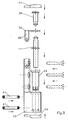
- Fig.3
- eine Explosionszeichnung des Rahmenbandes der Fig.1,
- Fig.4
- eine Aufsicht auf das Rahmenband der Fig.3,
- Fig.5
- eine Seitenansicht eines Drehbandkörpers,
- Fig.6
- eine Explosionszeichnung eines Flügelbandes in Vertikalaufsicht auf dessen Teile,
- Fig.7
- eine der Fig.1 entsprechende Darstellung eines dreiteiligen Drehbandes,
- Fig.7a
- eine der Fig.1a entsprechende Darstellung des Bandes der Fig.7,
- Fig.8
- eine der Fig.2 entsprechende Darstellung eines Drehbandes der Fig.7,
- Fig.9
- eine Explosionszeichnung des Rahmenbandes der Fig.7,
- Fig.10a,b
- zwei sich ergänzende Explosionszeichnungen eines kompletten Drehbandes einer weiteren Ausführungsform, und
- Fig.11
- eine der Fig.6 ähnliche Darstellung einer Explosionszeichnung eines Flügelbandes in Ausgestaltung gemäß Fig.10.
Claims (27)
- Drehband für Türen oder Fenster, mit einem an einem Flügel anzuschlagenden Flügelband (10,10a), das mit einer Gelenkachse (11,11a) an einem an einem Blendrahmen zu befestigenden Rahmenband (12,12a) angelenkt ist, mit einer in das Flügelband (10,10a) integrierten, horizontale Flügelverstellungen gestattenden Seitenverstelleinrichtung (13,13a), und mit einer vertikale Flügelverstellungen gestattenden Höhenverstelleinrichtung (14,14a), dadurch gekennzeichnet, daß die Höhenverstelleinrichtung (14,14a) gemeinsam mit der Seitenverstelleinrichtung (13,13a) in das Flügelband (10,10a) integriert ist.
- Drehband für Türen oder Fenster nach Anspruch 1, dadurch gekennzeichnet, daß die Höhen- und Seitenverstelleinrichtungen (14,13,14a,13a) mittels eines Kreuzschlittens (15,15a) integriert sind, der mit einer ersten Schlittenplatte (16,16a) horizontal und mit einer zweiten Schlittenplatte (17,17a) vertikal verstellbar ist.
- Drehband für Türen oder Fenster nach Anspruch 1 oder 2, dadurch gekennzeichnet, daß die Beweglichkeit der Schlittenplatten (16,17) mittels des Flügelbandes (10,10a) von Ausnehmungen (18) oder Aussparungen (30,60) dieses Flügelbandes (10,10a) begrenzt ist.
- Drehband für Türen oder Fenster nach einem oder mehreren der Ansprüche 1 bis 3, dadurch gekennzeichnet, daß die erste Schlittenplatte (16) bzw. die zweite Schlittenplatte (17a) versenkt in einer Ausnehmung (18) des Flügelbandes (10) zwischen diesem und der zweiten Schlittenplatte (17) bzw. der ersten Schlittenplatte (16a) verstellbar ist.
- Drehband für Türen oder Fenster nach einem oder mehreren der Ansprüche 1 bis 4, dadurch gekennzeichnet, daß die zweite Schlittenplatte (17) an der ersten Schlittenplatte (16) horizontal unverstellbar, jedoch vertikal begrenzt verstellbar ist oder daß die erste Schlittenplatte (16a) an der zweiten Schlittenplatte (17a) horizontal begrenzt verstellbar, jedoch vertikal unverstellbar ist.
- Drehband für Türen oder Fenster nach einem oder mehreren der Ansprüche 1 bis 5, dadurch gekennzeichnet, daß die erste und die zweite Schlittenplatte (16,17) mit vertikalen Nuten (19) und Rippen (20) vertikal verstellbar in Eingriff sind oder daß die erste und die zweite Schlittenplatte (16a,17a) mit horizontalen Nuten (19a) und Rippen (20a) horizontal verstellbar in Eingriff sind.
- Drehband für Türen oder Fenster nach einem oder mehreren der Ansprüche 1 bis 6, dadurch gekennzeichnet, daß die zweite Schlittenplatte (17) innerhalb der die erste Schlittenplatte (16) aufnehmenden Ausnehmung (18) angeordnet und ihre vertikale Verstellbarkeit von dieser Ausnehmung (18) begrenzt ist.
- Drehband für Türen oder Fenster nach einem oder mehreren der Ansprüche 1 bis 7, dadurch gekennzeichnet, daß die zweite Schlittenplatte (17) mit einer flügelseitigen Außenwand (21) des Flügelbandes (10) fluchtet.
- Drehband für Türen oder Fenster nach einem oder mehreren der Ansprüche 1 bis 8, dadurch gekennzeichnet, daß die zweite Schlittenplatte (17,17a) praktisch eine durch die Höhe des Flügelbandes bestimmte Höhe aufweist, abzüglich der vertikalen Verstellhöhe und der zur Ausbildung der die zweite Schlittenplatte (17,17a) aufnehmenden Ausnehmung (18,18a) benötigten Wandstärken des Flügelbandes (10,10a), und daß die zweite Schlittenplatte (17,17a) eine durch die Breite des Flügelbandes (10,10a) bestimmte Breite aufweist, abzüglich der horizontalen Verstellbreite und der zur Ausbildung der die zweite Schlittenplatte (17,17a) aufnehmenden Ausnehmung (18,18a) benötigten Wandstärken des Flügelbandes (10,10a).
- Drehband für Türen oder Fenster nach einem oder mehreren der Ansprüche 1 bis 9, dadurch gekennzeichnet, daß die zweite Schlittenplatte (17) oder eine flügelseitige Klemmplatte (25a)nahe Ecken und/oder Kanten einstückige oder starr angebrachte, in den Flügel eingreifende Tragstifte (59,59a) und/oder Haltekrallen aufweist.
- Drehband für Türen oder Fenster nach einem oder mehreren der Ansprüche 1 bis 10, dadurch gekennzeichnet, daß zwischen der ersten/zweiten Schlittenplatte (16/17a) und dem Flügelband eine horizontale/vertikale Verstellschraube (22/22a) und zwischen der zweiten/ersten und der ersten/zweiten Schlittenplatte (17,16/16a,17a) eine vertikale Verstellschraube (23,23a) angeordnet ist, daß Schraubenköpfe (22',23',22a',23a') der Verstellschrauben (22,23,22a,23a) je einer Durchgriffsöffnung (24,58,24a,58a) des Flügelbandes (10,10a) benachbart sind, daß die horizontale Verstellschraube (22,22a) mit ihrem Schraubenkopf (22',22a') in das Flügelband (10)/die erste Schlittenplatte (16a) unverstellbar eingreift sowie auf einem Schraubenschaft (22'',22a'') eine in die erste Schlittenplatte (16,16a) formschlüssig eingreifende Verstellmutter (22''',22a''') aufweist, und daß die vertikale Verstellschraube (23,23a) mit ihrem Schraubenkopf (23',23a') in die erste Schlittenplatte (16)/ das Flügelband (10a) unverstellbar eingreift sowie auf einem Schraubenschaft eine in die zweite Schlittenplatte (17,17a) formschlüssig eingreifende Verstellmutter aufweist.
- Drehband für Türen oder Fenster nach einem oder mehreren der Ansprüche 1 bis 10, dadurch gekennzeichnet, daß das Flügelband (10,10a) eine Klemmplatte (25,25a) aufweist, mit der es gemeinsam mit dem Kreuzschlitten (15,15a) am Flügel unverschieblich zu befestigen ist.
- Drehband für Türen oder Fenster nach einem oder mehreren der Ansprüche 1 bis 12, dadurch gekennzeichnet, daß der Kreuzschlitten (15,15a) flügelseitig oder flügelabgewendet einer Führungswand (26,26a) des Flügelbandes (10,10a) und die Klemmplatte (25,25a) auf der dem Kreuzschlitten (15,15a) abgewendeten Seite der Führungswand (26,26a) angeordnet sind.
- Drehband für Türen oder Fenster nach einem oder mehreren der Ansprüche 1 bis 13, dadurch gekennzeichnet, daß die Klemmplatte (25,25a) in einer flügelabgewendeten/flügelzugewendeten Ausnehmung (27,27a) des Flügelbandes (10,10a) angeordnet ist und mit dessen Außenfläche (28,21a) bündig liegt oder geringfügig vorspringt.
- Drehband für Türen oder Fenster nach einem oder mehreren der Anprüche 1 bis 14, dadurch gekennzeichnet, daß die Klemmplatte (25) und die zweite Schlittenplatte (17) fluchtende, Befestigungsschrauben führende Durchsteckbohrungen (29) aufweisen, daß die erste Schlittenplatte (16) ihre Vertikalverstellungen zulassende Vertikalschlitze (16') hat, und daß die Führungswand (26) des Flügelbandes (10) mit vertikale und horizontale Bandbewegungen bezüglich der Befestigungsschrauben zulassenden Aussparungen (30) versehen ist.
- Drehband für Türen oder Fenster nach einem oder mehreren der Ansprüche 1 bis 15, dadurch gekennzeichnet, daß die Klemmplatte (25) mit Führungsstiften (31) durch Aussparungen (30) des Flügelbandes (10) und Vertikalschlitze (32) der ersten Schlittenplatte (16) in die zweite Schlittenplatte (17) eingreift und bedarfsweise fest damit verbunden ist.
- Drehband für Türen oder Fenster nach einem oder mehreren der Ansprüche 1 bis 16, dadurch gekennzeichnet, daß eine Schlittenplatte (17a) in einer vertikalen oder horizontalen Aussparung (60) des Flügelbandes (10a) oder dessen Führungswand (26,26a) vertikal oder horizontal begrenzt verstellbar ist.
- Drehband für Türen oder Fenster nach einem oder mehreren der Ansprüche 1 bis 17, dadurch gekennzeichnet, daß die zweite Schlittenplatte (17a) mit einer Führungsleiste (61) in die vertikale Aussparung (60') und/oder mit Führungsnocken (61') in vertikale Führungsrinnen (60'') der Führungswand (26a) eingreift, und daß die Führungsleiste (61) bedarfsweise über horizontale Mitnahmenuten (62) und -rippen (63) mit der flügelseitigen Klemmplatte (25a) in vertikalem Mitnahmeeingriff steht.
- Drehband für Türen oder Fenster nach einem oder mehreren der Ansprüche 1 bis 18, dadurch gekennzeichnet, daß die erste Schlittenplatte (16a) Aussparungen (60) der Führungswand (26a) durchgreifende Stützvorsprünge (64) aufweist, die auf der Klemmplatte (25a) abgestützt sind und bedarfsweise Befestigungsschrauben führende Durchsteckbohrungen (65) aufweisen.
- Drehband für Türen oder Fenster nach einem oder mehreren der Ansprüche 1 bis 19, dadurch gekennzeichnet, daß das Flügelband (10) sichtseitig eine unverstellbare, die Klemmplatte (25)/ die erste Schlittenplatte (16a) abdeckende Abdeckkappe (33,33a) aufweist.
- Drehband für Türen oder Fenster nach einem oder mehreren der Ansprüche 1 bis 20, dadurch gekennzeichnet, daß eine Achsaufnahmebohrung (10') des Flügelbandes (10) seitlich zugänglich, aber von der Abdeckkappe (33) abgedeckt ist.
- Drehband für Türen oder Fenster nach einem oder mehreren der Ansprüche 1 bis 21, dadurch gekennzeichnet, daß im Rahmenband (12) eine dreheinstellbare Achsaufnahmebuchse (34) mit einer exzentrischen Achsaufnahmebohrung (34') vorhanden ist.
- Drehband für Türen oder Fenster, mit einem an einem Flügel anzuschlagenden Flügelband (10), das mit einer Gelenkachse (11) an einem an einem Blendrahmen zu befestigenden Rahmenband (12) angelenkt ist, insbesondere nach einem oder mehreren der Ansprüche 1 bis 19, dadurch gekennzeichnet, daß die Gelenkachse (11) eine Eingriffslänge (48) in das Flügelband (10) aufweist, die kürzer als dessen Achsaufnahmebohrung (10') ist, in deren oberes freies Bohrungsende (35) ein am Rahmenband (12) lösbar befestigter Achsstift (36) eingesetzt ist.
- Drehband für Türen oder Fenster nach einem oder mehreren der Ansprüche 1 bis 23, dadurch gekennzeichnet, daß das Flügelband (10) einen zwischen die Gelenkachse (11) und den Achsstift (36) in die Achsaufnahmebohrung (10') eingreifenden Achsanschlag (37) aufweist.
- Drehband für Türen oder Fenster nach einem oder mehreren der Anprüche 1 oder 23, dadurch gekennzeichnet, daß die Gelenkachse (11) und der Achsstift (36) nahe dem Achsanschlag (37) je eine Ringnut (38) aufweisen, in die je ein im Flügelband (10) lösbar befestigter Haltestift (39) tangential eingreift.
- Drehband für Türen oder Fenster nach einem oder mehreren der Ansprüche 1 bis 25, dadurch gekennzeichnet, daß der Achsstift (36) eines zweiteiligen Drehbandes mit einer Querlasche (39) gegen horizontale Belastungen gehalten ist, die am Rahmenband (12) bedarfsweise lösbar befestigt ist.
- Drehband für Türen oder Fenster nach einem der Ansprüche 1 bis 26, dadurch gekennzeichnet, daß der Achsstift (36) eines dreiteiligen Drehbandes und dessen Gelenkachse (11) gleich ausgebildet und mit einander zugewendeten Ringnuten (38) in der Achsaufnahmebohrung (10') des Flügelbandes (10) angeordnet sind.
Priority Applications (1)
| Application Number | Priority Date | Filing Date | Title |
|---|---|---|---|
| EP04008276A EP1437467B1 (de) | 1999-10-04 | 2000-03-08 | Drehband für Türen oder Fenster |
Applications Claiming Priority (2)
| Application Number | Priority Date | Filing Date | Title |
|---|---|---|---|
| DE19947670 | 1999-10-04 | ||
| DE19947670A DE19947670B4 (de) | 1999-10-04 | 1999-10-04 | Drehband für Türen oder Fenster |
Related Child Applications (2)
| Application Number | Title | Priority Date | Filing Date |
|---|---|---|---|
| EP04008276A Division EP1437467B1 (de) | 1999-10-04 | 2000-03-08 | Drehband für Türen oder Fenster |
| EP04008276.0 Division-Into | 2004-04-06 |
Publications (3)
| Publication Number | Publication Date |
|---|---|
| EP1091066A2 true EP1091066A2 (de) | 2001-04-11 |
| EP1091066A3 EP1091066A3 (de) | 2001-08-01 |
| EP1091066B1 EP1091066B1 (de) | 2005-07-27 |
Family
ID=7924378
Family Applications (3)
| Application Number | Title | Priority Date | Filing Date |
|---|---|---|---|
| EP00104918A Expired - Lifetime EP1091066B1 (de) | 1999-10-04 | 2000-03-08 | Drehband für Türen oder Fenster |
| EP04008276A Expired - Lifetime EP1437467B1 (de) | 1999-10-04 | 2000-03-08 | Drehband für Türen oder Fenster |
| EP00121666A Expired - Lifetime EP1091067B1 (de) | 1999-10-04 | 2000-10-04 | Drehband für Türen oder Fenster |
Family Applications After (2)
| Application Number | Title | Priority Date | Filing Date |
|---|---|---|---|
| EP04008276A Expired - Lifetime EP1437467B1 (de) | 1999-10-04 | 2000-03-08 | Drehband für Türen oder Fenster |
| EP00121666A Expired - Lifetime EP1091067B1 (de) | 1999-10-04 | 2000-10-04 | Drehband für Türen oder Fenster |
Country Status (5)
| Country | Link |
|---|---|
| EP (3) | EP1091066B1 (de) |
| AT (2) | ATE300650T1 (de) |
| DE (3) | DE19947670B4 (de) |
| DK (1) | DK1091066T3 (de) |
| PL (1) | PL200031B1 (de) |
Cited By (7)
| Publication number | Priority date | Publication date | Assignee | Title |
|---|---|---|---|---|
| GB2381291A (en) * | 2001-10-27 | 2003-04-30 | Window Fab & Fixing Supplies | Hinge with concealed fasteners |
| GB2383081A (en) * | 2001-12-13 | 2003-06-18 | J K Furnex Ltd | Hinge providing height, lateral and compression adjustment |
| EP1508662A1 (de) * | 2003-08-13 | 2005-02-23 | Steinbach & Vollmann GmbH & Co. KG | Türscharnier |
| EP2169163A1 (de) * | 2008-09-30 | 2010-03-31 | Eco Schulte GmbH & Co. Kg | Höhenverstellbares Band |
| CN107700993A (zh) * | 2017-11-07 | 2018-02-16 | 佛山市金砥柱建筑装饰材料有限公司 | 合页上下调节结构 |
| IT201800006082A1 (it) * | 2018-06-06 | 2019-12-06 | Gruppo cerniere per ante | |
| CN111636781A (zh) * | 2020-06-30 | 2020-09-08 | 河南天合铰链有限公司 | 一种半嵌入式平衡铰链及带有门体的装置 |
Families Citing this family (9)
| Publication number | Priority date | Publication date | Assignee | Title |
|---|---|---|---|---|
| DE20100745U1 (de) * | 2001-01-15 | 2002-05-23 | Niemann, Hans Dieter, 50169 Kerpen | Band für Türen oder Fenster |
| CH698620B1 (de) * | 2006-07-21 | 2009-09-15 | Harald Sitter | Scharnier |
| DE202007011946U1 (de) * | 2007-08-28 | 2009-01-02 | Gluske-Bkv Gmbh | Befestigungseinrichtung mit Verstellung |
| IT1391640B1 (it) * | 2008-10-28 | 2012-01-17 | Omf S R L | Dispositivo di regolazione per cerniere a scomparsa e cerniera a scomparsa comprendente detto dispositivo di regolazione |
| CH700566B1 (de) | 2009-03-02 | 2013-04-30 | Christian Sitter | Scharnier. |
| IT1396871B1 (it) * | 2009-12-24 | 2012-12-20 | Gsg Int Spa | Cerniera per infissi pesanti. |
| DE202010000416U1 (de) * | 2010-03-19 | 2011-08-01 | Dr. Hahn Gmbh & Co. Kg | Bandanordnung für Türen, Fenster o.dgl. |
| CN102837722B (zh) * | 2012-09-29 | 2014-08-13 | 常州星宇车灯股份有限公司 | 车灯镀铝工件挂架的转运装置 |
| BE1029466B1 (nl) * | 2021-06-07 | 2023-01-09 | Sobinco Fa | Scharnier voor een raam of een deur met scharnierblad met bijhorend hulpstuk met regelbare dikte voor de zijdelingse regeling van het raam of de deur |
Family Cites Families (10)
| Publication number | Priority date | Publication date | Assignee | Title |
|---|---|---|---|---|
| US1103607A (en) * | 1913-08-14 | 1914-07-14 | Jacob Hyson Moore | Vertically-adjustable hinge. |
| DE3401253A1 (de) * | 1984-01-16 | 1985-07-18 | Lunke & Sohn Gmbh, 5810 Witten | Demontierbares kfz-tuerscharnier sowie aufhaengung einer kfz-tuer |
| EP0314616A1 (de) * | 1987-10-28 | 1989-05-03 | Gutknecht S.A. | Scharnierband zum Aufhängen von Flügeln |
| DE9206448U1 (de) * | 1992-05-13 | 1993-09-16 | Dr. Hahn GmbH & Co. KG, 41189 Mönchengladbach | Scharnierband |
| DE9317065U1 (de) * | 1993-11-08 | 1994-03-03 | Schüring GmbH & Co Fenstertechnologie KG, 51147 Köln | Einstellbares Gelenkband für Türen oder Fenster |
| DE19642638C5 (de) * | 1996-10-16 | 2004-04-01 | Simonswerk, Gmbh | Türband |
| DE19732702A1 (de) * | 1997-07-30 | 1999-02-04 | Haps & Sohn Gmbh & Co Kg | Bandlappen für ein Tür- oder Fensterband |
| DE29721037U1 (de) * | 1997-11-28 | 1999-04-22 | Niemann, Hans Dieter, 50169 Kerpen | Tür- oder Fensterband |
| DE19801434C2 (de) * | 1998-01-16 | 2003-07-03 | Niemann Hans Dieter | Tür- oder Fensterband |
| DE29817807U1 (de) * | 1998-10-06 | 1999-06-10 | Breuer & Schmitz, 42719 Solingen | Dreidimensional verstellbares Aufschraubband für Tür- oder Fensterflügel |
-
1999
- 1999-10-04 DE DE19947670A patent/DE19947670B4/de not_active Expired - Fee Related
-
2000
- 2000-03-08 EP EP00104918A patent/EP1091066B1/de not_active Expired - Lifetime
- 2000-03-08 DK DK00104918T patent/DK1091066T3/da active
- 2000-03-08 AT AT00104918T patent/ATE300650T1/de active
- 2000-03-08 AT AT04008276T patent/ATE513968T1/de active
- 2000-03-08 DE DE50010818T patent/DE50010818D1/de not_active Expired - Lifetime
- 2000-03-08 EP EP04008276A patent/EP1437467B1/de not_active Expired - Lifetime
- 2000-09-27 PL PL342800A patent/PL200031B1/pl unknown
- 2000-10-04 EP EP00121666A patent/EP1091067B1/de not_active Expired - Lifetime
- 2000-10-04 DE DE50009090T patent/DE50009090D1/de not_active Expired - Lifetime
Cited By (9)
| Publication number | Priority date | Publication date | Assignee | Title |
|---|---|---|---|---|
| GB2381291A (en) * | 2001-10-27 | 2003-04-30 | Window Fab & Fixing Supplies | Hinge with concealed fasteners |
| GB2381291B (en) * | 2001-10-27 | 2004-12-29 | Window Fab & Fixing Supplies | Hinge |
| GB2383081A (en) * | 2001-12-13 | 2003-06-18 | J K Furnex Ltd | Hinge providing height, lateral and compression adjustment |
| GB2383081B (en) * | 2001-12-13 | 2005-06-01 | J K Furnex Ltd | Hinges |
| EP1508662A1 (de) * | 2003-08-13 | 2005-02-23 | Steinbach & Vollmann GmbH & Co. KG | Türscharnier |
| EP2169163A1 (de) * | 2008-09-30 | 2010-03-31 | Eco Schulte GmbH & Co. Kg | Höhenverstellbares Band |
| CN107700993A (zh) * | 2017-11-07 | 2018-02-16 | 佛山市金砥柱建筑装饰材料有限公司 | 合页上下调节结构 |
| IT201800006082A1 (it) * | 2018-06-06 | 2019-12-06 | Gruppo cerniere per ante | |
| CN111636781A (zh) * | 2020-06-30 | 2020-09-08 | 河南天合铰链有限公司 | 一种半嵌入式平衡铰链及带有门体的装置 |
Also Published As
| Publication number | Publication date |
|---|---|
| PL200031B1 (pl) | 2008-11-28 |
| DE50009090D1 (de) | 2005-02-03 |
| EP1091067A1 (de) | 2001-04-11 |
| EP1437467A2 (de) | 2004-07-14 |
| DE19947670B4 (de) | 2006-10-26 |
| EP1437467A3 (de) | 2008-07-30 |
| EP1091066A3 (de) | 2001-08-01 |
| DE50010818D1 (de) | 2005-09-01 |
| DE19947670A1 (de) | 2001-08-09 |
| EP1091067B1 (de) | 2004-12-29 |
| DK1091066T3 (da) | 2005-10-24 |
| EP1091066B1 (de) | 2005-07-27 |
| EP1437467B1 (de) | 2011-06-22 |
| PL342800A1 (en) | 2001-04-09 |
| ATE513968T1 (de) | 2011-07-15 |
| ATE300650T1 (de) | 2005-08-15 |
Similar Documents
| Publication | Publication Date | Title |
|---|---|---|
| AT394081B (de) | Verstellbares tuer- und fensterband | |
| DE60000099T2 (de) | Scharnier für einen zu öffnenden Tür- oder Fensterrahmen | |
| EP0259618B1 (de) | Während und nach der Montage verstellbares Tür- und Fensterband | |
| EP1091066B1 (de) | Drehband für Türen oder Fenster | |
| EP2297418B1 (de) | Scharnier | |
| DE69000171T2 (de) | Verstellbares und nichtzerlegbares scharnier fuer tueren, fenster oder aehnliche rahmen. | |
| DE3504921A1 (de) | Scharnierband fuer tueren, insbesondere scharnierband mit drei bandgliedern | |
| DE20304646U1 (de) | Beschlag | |
| EP2754813B1 (de) | Band, insbesondere für Kunststoff-Türen und -Fenster | |
| EP0386342A1 (de) | Flügeltür, insbesondere in einer Duschabtrennung | |
| AT14999U1 (de) | Band für eine Tür oder ein Fenster | |
| EP0223186B1 (de) | Justierbares Tür- oder Fensterband | |
| EP0318422B1 (de) | Einstellbares Gelenkband, insbesondere für Fenster und Türen | |
| DE69612902T2 (de) | Scharnier | |
| EP0470601A1 (de) | Gerät zum Anbringen der Bohrungen zum Befestigen der Rahmenbandteile eines Fensters oder einer Türe | |
| EP0628688B1 (de) | Lager für die wenigstens drehbare Lagerung eines Flügels, eines Fensters, einer Tür oder dergleichen | |
| CH690451A5 (de) | Scharnier. | |
| EP2740872B1 (de) | Zur verdeckten anordnung vorgesehenes ecklager | |
| EP0930411B1 (de) | Tür oder Fensterband | |
| EP1223275B1 (de) | Band für Türen oder Fenster | |
| EP1314844A1 (de) | Tür- oder Fensterband | |
| DE20014727U1 (de) | Band für Türen, Fenster u.dgl. | |
| EP1922468A1 (de) | Band für türen, fenster oder dergleichen | |
| DE20004106U1 (de) | Drehband für Fenster oder Türen | |
| EP1245771B1 (de) | Tür- oder Fensterband |
Legal Events
| Date | Code | Title | Description |
|---|---|---|---|
| PUAI | Public reference made under article 153(3) epc to a published international application that has entered the european phase |
Free format text: ORIGINAL CODE: 0009012 |
|
| AK | Designated contracting states |
Kind code of ref document: A2 Designated state(s): AT BE CH CY DE DK ES FI FR GB GR IE IT LI LU MC NL PT SE |
|
| AX | Request for extension of the european patent |
Free format text: AL;LT;LV;MK;RO;SI |
|
| PUAL | Search report despatched |
Free format text: ORIGINAL CODE: 0009013 |
|
| RIC1 | Information provided on ipc code assigned before grant |
Free format text: 7E 05D 7/04 A, 7E 05D 7/10 B |
|
| AK | Designated contracting states |
Kind code of ref document: A3 Designated state(s): AT BE CH CY DE DK ES FI FR GB GR IE IT LI LU MC NL PT SE |
|
| AX | Request for extension of the european patent |
Free format text: AL;LT;LV;MK;RO;SI |
|
| 17P | Request for examination filed |
Effective date: 20011206 |
|
| AKX | Designation fees paid |
Free format text: AT BE CH CY DE DK ES FI FR GB GR IE IT LI LU MC NL PT SE |
|
| 17Q | First examination report despatched |
Effective date: 20030702 |
|
| GRAP | Despatch of communication of intention to grant a patent |
Free format text: ORIGINAL CODE: EPIDOSNIGR1 |
|
| GRAS | Grant fee paid |
Free format text: ORIGINAL CODE: EPIDOSNIGR3 |
|
| GRAA | (expected) grant |
Free format text: ORIGINAL CODE: 0009210 |
|
| AK | Designated contracting states |
Kind code of ref document: B1 Designated state(s): AT BE CH CY DE DK ES FI FR GB GR IE IT LI LU MC NL PT SE |
|
| PG25 | Lapsed in a contracting state [announced via postgrant information from national office to epo] |
Ref country code: FI Free format text: LAPSE BECAUSE OF FAILURE TO SUBMIT A TRANSLATION OF THE DESCRIPTION OR TO PAY THE FEE WITHIN THE PRESCRIBED TIME-LIMIT Effective date: 20050727 Ref country code: IE Free format text: LAPSE BECAUSE OF FAILURE TO SUBMIT A TRANSLATION OF THE DESCRIPTION OR TO PAY THE FEE WITHIN THE PRESCRIBED TIME-LIMIT Effective date: 20050727 |
|
| REG | Reference to a national code |
Ref country code: GB Ref legal event code: FG4D Free format text: NOT ENGLISH |
|
| REG | Reference to a national code |
Ref country code: CH Ref legal event code: EP |
|
| REG | Reference to a national code |
Ref country code: IE Ref legal event code: FG4D Free format text: LANGUAGE OF EP DOCUMENT: GERMAN |
|
| REF | Corresponds to: |
Ref document number: 50010818 Country of ref document: DE Date of ref document: 20050901 Kind code of ref document: P |
|
| REG | Reference to a national code |
Ref country code: DK Ref legal event code: T3 |
|
| GBT | Gb: translation of ep patent filed (gb section 77(6)(a)/1977) |
Effective date: 20051003 |
|
| PG25 | Lapsed in a contracting state [announced via postgrant information from national office to epo] |
Ref country code: GR Free format text: LAPSE BECAUSE OF FAILURE TO SUBMIT A TRANSLATION OF THE DESCRIPTION OR TO PAY THE FEE WITHIN THE PRESCRIBED TIME-LIMIT Effective date: 20051027 Ref country code: SE Free format text: LAPSE BECAUSE OF FAILURE TO SUBMIT A TRANSLATION OF THE DESCRIPTION OR TO PAY THE FEE WITHIN THE PRESCRIBED TIME-LIMIT Effective date: 20051027 |
|
| PG25 | Lapsed in a contracting state [announced via postgrant information from national office to epo] |
Ref country code: PT Free format text: LAPSE BECAUSE OF FAILURE TO SUBMIT A TRANSLATION OF THE DESCRIPTION OR TO PAY THE FEE WITHIN THE PRESCRIBED TIME-LIMIT Effective date: 20051227 |
|
| REG | Reference to a national code |
Ref country code: IE Ref legal event code: FD4D |
|
| PG25 | Lapsed in a contracting state [announced via postgrant information from national office to epo] |
Ref country code: LI Free format text: LAPSE BECAUSE OF NON-PAYMENT OF DUE FEES Effective date: 20060331 Ref country code: MC Free format text: LAPSE BECAUSE OF NON-PAYMENT OF DUE FEES Effective date: 20060331 Ref country code: CH Free format text: LAPSE BECAUSE OF NON-PAYMENT OF DUE FEES Effective date: 20060331 Ref country code: LU Free format text: LAPSE BECAUSE OF NON-PAYMENT OF DUE FEES Effective date: 20060331 |
|
| ET | Fr: translation filed | ||
| PLBE | No opposition filed within time limit |
Free format text: ORIGINAL CODE: 0009261 |
|
| STAA | Information on the status of an ep patent application or granted ep patent |
Free format text: STATUS: NO OPPOSITION FILED WITHIN TIME LIMIT |
|
| 26N | No opposition filed |
Effective date: 20060428 |
|
| REG | Reference to a national code |
Ref country code: CH Ref legal event code: PL |
|
| PG25 | Lapsed in a contracting state [announced via postgrant information from national office to epo] |
Ref country code: CY Free format text: LAPSE BECAUSE OF FAILURE TO SUBMIT A TRANSLATION OF THE DESCRIPTION OR TO PAY THE FEE WITHIN THE PRESCRIBED TIME-LIMIT Effective date: 20050727 |
|
| PG25 | Lapsed in a contracting state [announced via postgrant information from national office to epo] |
Ref country code: ES Free format text: LAPSE BECAUSE OF NON-PAYMENT OF DUE FEES Effective date: 20060331 |
|
| REG | Reference to a national code |
Ref country code: DE Ref legal event code: R081 Ref document number: 50010818 Country of ref document: DE Owner name: ROTO GLUSKE-BKV GMBH, DE Free format text: FORMER OWNER: HANS DIETER NIEMANN, 50169 KERPEN, DE Effective date: 20110705 Ref country code: DE Ref legal event code: R081 Ref document number: 50010818 Country of ref document: DE Owner name: ROTO GLUSKE-BKV GMBH, DE Free format text: FORMER OWNER: NIEMANN, HANS DIETER, 50169 KERPEN, DE Effective date: 20110705 |
|
| REG | Reference to a national code |
Ref country code: FR Ref legal event code: PLFP Year of fee payment: 17 |
|
| REG | Reference to a national code |
Ref country code: FR Ref legal event code: PLFP Year of fee payment: 18 |
|
| PGFP | Annual fee paid to national office [announced via postgrant information from national office to epo] |
Ref country code: NL Payment date: 20170321 Year of fee payment: 18 Ref country code: FR Payment date: 20170322 Year of fee payment: 18 |
|
| PGFP | Annual fee paid to national office [announced via postgrant information from national office to epo] |
Ref country code: BE Payment date: 20170321 Year of fee payment: 18 Ref country code: AT Payment date: 20170322 Year of fee payment: 18 Ref country code: DK Payment date: 20170321 Year of fee payment: 18 Ref country code: GB Payment date: 20170322 Year of fee payment: 18 |
|
| PGFP | Annual fee paid to national office [announced via postgrant information from national office to epo] |
Ref country code: IT Payment date: 20170323 Year of fee payment: 18 |
|
| PGFP | Annual fee paid to national office [announced via postgrant information from national office to epo] |
Ref country code: DE Payment date: 20180312 Year of fee payment: 19 |
|
| REG | Reference to a national code |
Ref country code: DK Ref legal event code: EBP Effective date: 20180331 |
|
| REG | Reference to a national code |
Ref country code: NL Ref legal event code: MM Effective date: 20180401 |
|
| REG | Reference to a national code |
Ref country code: AT Ref legal event code: MM01 Ref document number: 300650 Country of ref document: AT Kind code of ref document: T Effective date: 20180308 |
|
| GBPC | Gb: european patent ceased through non-payment of renewal fee |
Effective date: 20180308 |
|
| REG | Reference to a national code |
Ref country code: BE Ref legal event code: MM Effective date: 20180331 |
|
| PG25 | Lapsed in a contracting state [announced via postgrant information from national office to epo] |
Ref country code: NL Free format text: LAPSE BECAUSE OF NON-PAYMENT OF DUE FEES Effective date: 20180401 |
|
| PG25 | Lapsed in a contracting state [announced via postgrant information from national office to epo] |
Ref country code: AT Free format text: LAPSE BECAUSE OF NON-PAYMENT OF DUE FEES Effective date: 20180308 |
|
| PG25 | Lapsed in a contracting state [announced via postgrant information from national office to epo] |
Ref country code: IT Free format text: LAPSE BECAUSE OF NON-PAYMENT OF DUE FEES Effective date: 20180308 Ref country code: GB Free format text: LAPSE BECAUSE OF NON-PAYMENT OF DUE FEES Effective date: 20180308 Ref country code: BE Free format text: LAPSE BECAUSE OF NON-PAYMENT OF DUE FEES Effective date: 20180331 |
|
| PG25 | Lapsed in a contracting state [announced via postgrant information from national office to epo] |
Ref country code: FR Free format text: LAPSE BECAUSE OF NON-PAYMENT OF DUE FEES Effective date: 20180331 |
|
| PG25 | Lapsed in a contracting state [announced via postgrant information from national office to epo] |
Ref country code: DK Free format text: LAPSE BECAUSE OF NON-PAYMENT OF DUE FEES Effective date: 20180331 |
|
| REG | Reference to a national code |
Ref country code: DE Ref legal event code: R082 Ref document number: 50010818 Country of ref document: DE Representative=s name: DRAUDT, AXEL, DIPL.-ING., DE |
|
| REG | Reference to a national code |
Ref country code: DE Ref legal event code: R119 Ref document number: 50010818 Country of ref document: DE |
|
| PG25 | Lapsed in a contracting state [announced via postgrant information from national office to epo] |
Ref country code: DE Free format text: LAPSE BECAUSE OF NON-PAYMENT OF DUE FEES Effective date: 20191001 |