EP1088616B1 - Dispositif de rotation ou pivotement d'une machine-outil - Google Patents
Dispositif de rotation ou pivotement d'une machine-outil Download PDFInfo
- Publication number
- EP1088616B1 EP1088616B1 EP00120215A EP00120215A EP1088616B1 EP 1088616 B1 EP1088616 B1 EP 1088616B1 EP 00120215 A EP00120215 A EP 00120215A EP 00120215 A EP00120215 A EP 00120215A EP 1088616 B1 EP1088616 B1 EP 1088616B1
- Authority
- EP
- European Patent Office
- Prior art keywords
- clamping
- rotary
- pivoting device
- ring
- pressure application
- Prior art date
- Legal status (The legal status is an assumption and is not a legal conclusion. Google has not performed a legal analysis and makes no representation as to the accuracy of the status listed.)
- Expired - Lifetime
Links
Images


Classifications
-
- B—PERFORMING OPERATIONS; TRANSPORTING
- B23—MACHINE TOOLS; METAL-WORKING NOT OTHERWISE PROVIDED FOR
- B23Q—DETAILS, COMPONENTS, OR ACCESSORIES FOR MACHINE TOOLS, e.g. ARRANGEMENTS FOR COPYING OR CONTROLLING; MACHINE TOOLS IN GENERAL CHARACTERISED BY THE CONSTRUCTION OF PARTICULAR DETAILS OR COMPONENTS; COMBINATIONS OR ASSOCIATIONS OF METAL-WORKING MACHINES, NOT DIRECTED TO A PARTICULAR RESULT
- B23Q1/00—Members which are comprised in the general build-up of a form of machine, particularly relatively large fixed members
- B23Q1/25—Movable or adjustable work or tool supports
- B23Q1/26—Movable or adjustable work or tool supports characterised by constructional features relating to the co-operation of relatively movable members; Means for preventing relative movement of such members
- B23Q1/28—Means for securing sliding members in any desired position
-
- B—PERFORMING OPERATIONS; TRANSPORTING
- B23—MACHINE TOOLS; METAL-WORKING NOT OTHERWISE PROVIDED FOR
- B23Q—DETAILS, COMPONENTS, OR ACCESSORIES FOR MACHINE TOOLS, e.g. ARRANGEMENTS FOR COPYING OR CONTROLLING; MACHINE TOOLS IN GENERAL CHARACTERISED BY THE CONSTRUCTION OF PARTICULAR DETAILS OR COMPONENTS; COMBINATIONS OR ASSOCIATIONS OF METAL-WORKING MACHINES, NOT DIRECTED TO A PARTICULAR RESULT
- B23Q1/00—Members which are comprised in the general build-up of a form of machine, particularly relatively large fixed members
- B23Q1/25—Movable or adjustable work or tool supports
- B23Q1/44—Movable or adjustable work or tool supports using particular mechanisms
- B23Q1/50—Movable or adjustable work or tool supports using particular mechanisms with rotating pairs only, the rotating pairs being the first two elements of the mechanism
- B23Q1/52—Movable or adjustable work or tool supports using particular mechanisms with rotating pairs only, the rotating pairs being the first two elements of the mechanism a single rotating pair
-
- Y—GENERAL TAGGING OF NEW TECHNOLOGICAL DEVELOPMENTS; GENERAL TAGGING OF CROSS-SECTIONAL TECHNOLOGIES SPANNING OVER SEVERAL SECTIONS OF THE IPC; TECHNICAL SUBJECTS COVERED BY FORMER USPC CROSS-REFERENCE ART COLLECTIONS [XRACs] AND DIGESTS
- Y10—TECHNICAL SUBJECTS COVERED BY FORMER USPC
- Y10T—TECHNICAL SUBJECTS COVERED BY FORMER US CLASSIFICATION
- Y10T409/00—Gear cutting, milling, or planing
- Y10T409/30—Milling
- Y10T409/30868—Work support
- Y10T409/308736—Work support with position indicator or stop
-
- Y—GENERAL TAGGING OF NEW TECHNOLOGICAL DEVELOPMENTS; GENERAL TAGGING OF CROSS-SECTIONAL TECHNOLOGIES SPANNING OVER SEVERAL SECTIONS OF THE IPC; TECHNICAL SUBJECTS COVERED BY FORMER USPC CROSS-REFERENCE ART COLLECTIONS [XRACs] AND DIGESTS
- Y10—TECHNICAL SUBJECTS COVERED BY FORMER USPC
- Y10T—TECHNICAL SUBJECTS COVERED BY FORMER US CLASSIFICATION
- Y10T74/00—Machine element or mechanism
- Y10T74/14—Rotary member or shaft indexing, e.g., tool or work turret
- Y10T74/1418—Preselected indexed position
- Y10T74/1424—Sequential
- Y10T74/1453—Interlocked rotator and brake
- Y10T74/1459—Diverse-type brakes
- Y10T74/1465—Diverse-type brakes with axially acting friction brake
Definitions
- the invention relates to a turning or pivoting device of a machine tool, in particular an NC rotary table, with a twisted on a support or pivotally mounted machine part and a clamping device for releasable fixing of the machine part in desired angular positions. See, for example, US 5,918,510.
- the drive motors via a position control of the drive motors for the Pivoting or rotary movement of the table top done. It must from the drive motors However, a relatively large holding moment can be provided so that the tabletop, despite the e.g. possible during roughing high forces against rotation is ensured.
- the drive motors usually be sized accordingly large.
- the object of the invention is to provide a rotary or pivoting device of the above mentioned type to create a secure fixation of the rotatable or pivotable Machine part also possible without changes in position.
- the clamping device a clamping part arranged on the support with laterally yielding clamping elements for engagement in an annular groove on the rotatable or pivotable machine part and a relative to the clamping part movable pressing member for pressing the clamping elements has on at least one side wall of the annular groove.
- the clamping takes place of the rotatably mounted on a support or pivotally mounted machine part only via radial clamping forces, which do not contribute to a suit of the machine part lead the edition.
- a turntable with a horizontal tabletop e.g. by the radial clamping lowering or deformation of the table top and a resulting inaccuracies are avoided.
- the clamping part in a particularly advantageous embodiment of the on Pad fastenable clamping ring with evenly distributed over the circumference inner and outer clamping elements, by the pressure member to the inner and outer side wall of the annular groove can be pressed.
- the on the inner and outer Side wall of the annular groove acting radial forces cancel each other, so that at a clamping and no lateral displacement of the rotary or pivotable machine part relative to the edition results.
- the pressure member is as an intermediate the inner and outer clamping elements arranged conical ring with conical Formed contact surfaces.
- the pressure part is an increase in force from the axial to the radial clamping forces reachable.
- the annular groove and the associated clamping part are advantageously in the range arranged on the outer periphery of the rotatable or pivotable machine part. As a result, even with relatively low clamping forces a relative high holding torque can be generated.
- the axial adjustment of the pressure element is carried out in an easy-to-control design by a fluid-operated piston-and-cylinder arrangement, e.g. contains several evenly distributed over the circumference hydraulic cylinder.
- the But pressure part can also be adjusted by other suitable actuators.
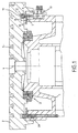
- a universal milling and Drilling machine contains a e.g. run as table slide or console edition 1, on which a table top 2 is designed as an axial angular contact ball bearing Bearing assembly 3 is mounted rotatably about a vertical axis of rotation 4.
- the Table top 2 has on its top several T-shaped flutes 5 for the Clamping of workpieces.
- the table top 2 can be used for clamping of Workpieces should also be provided with threaded bushes.
- the rotary drive of Table top 2 can by a arranged within the support 1 drive motor take place, which is not shown in Fig. 1.
- the support 1 includes a concentric with the axis of rotation 4 outer ring surface 6, on the one in Fig. 2 in perspective Clamping ring 7 with several uniformly distributed over its circumference clamping elements in the form of two spaced apart and opposite each other in the radial direction elastically flexible inner and outer ring segments 8 and 9 is attached.
- the relatively thin-walled ring segments 8 and 9 are at one upper annular surface 10 of the clamping ring 7 integrally formed in the axial direction above and engage in a concentric with the underside of the table top 2 to the rotation axis 4 arranged annular groove 11 a.
- each six inner and outer ring segments 8 and 9 is a coaxial to the clamping ring 7 and in Axial direction displaceable conical pressure ring 12 with oppositely inclined inner and outer conical surfaces 13 and 14 for the pressure of the radial compliant ring segments 8 and 9 arranged on the side walls of the annular groove 11.
- This will be a frictional connection reached between the support 1 and the table top 2, the rotation the tabletop 2 prevents.
- the ring segments return by themselves again a starting position back in between the ring segments and the walls the annular groove only a slight friction or a game exists.
- the hydraulic cylinders 19 are arranged as shown in FIG. 3 such that their piston rods 20 each with one between the ring segments 8 and 9 in the Clamping ring 7 provided through hole 21 and a corresponding Through hole 22 in the pressure ring 12 are aligned.
- Through the through holes 21 in the secured by screws 23 on the support 1 clamping ring. 7 are threaded bolts 24 out, which with its upper part via a nut 25 at fixed to the pressure ring 12 and with its lower part in a threaded bore 26th screwed into the piston rod 20 and secured by a lock nut 27 are.
- Fig. 1 Within the edition 1 is shown in Fig. 1 on the left side limit switch 28 arranged, the 12 when tightening the pressure ring to the support. 1 is pressed. This allows a review of the clamping or release position of the Pressure ring 12 done.
- clamping device may e.g. also for releasably fixing a swivel milling head or other rotary and Swivel devices of a machine tool can be used.
Landscapes
- Engineering & Computer Science (AREA)
- Mechanical Engineering (AREA)
- Machine Tool Units (AREA)
- Jigs For Machine Tools (AREA)
- Machine Tool Positioning Apparatuses (AREA)
Claims (7)
- Dispositif de rotation ou de pivotement d'une machine-outil, notamment une table circulaire à commande numérique, aveccaractérisé en ce queune pièce de machine (2) logée sur un support (1) de manière à pouvoir tourner ou pivoter, etun mécanisme de serrage (7, 12) pour la fixation amovible de la pièce de machine (2) dans les positions angulaires souhaitées,
le mécanisme de serrage (7, 12) comporte une pièce de serrage (7) disposée sur le support (1), avec des éléments de serrage (8, 9) latéraux élastiques s'engageant dans une rainure annulaire (11) sur la pièce de machine (2), et une pièce de pression (12) mobile par rapport à la pièce de serrage (7) pour presser les éléments de serrage (8, 9) sur une paroi latérale au moins de la rainure annulaire (11). - Dispositif de rotation ou de pivotement selon la revendication 1, caractérisé en ce que la pièce de serrage est une bague de serrage (7) pouvant se fixer sur le support (1), avec des éléments de serrage (8, 9) intérieurs et extérieurs régulièrement répartis à sa circonférence, lesquels sont comprimables par la pièce de pression (12) contre les parois intérieure et extérieure (17, 18) de la rainure annulaire (11).
- Dispositif de rotation ou de pivotement selon la revendication 1 ou 2, caractérisé en ce que les éléments de serrage (8, 9) sont des segments annulaires pouvant être élastiquement fléchis dans une direction radiale.
- Dispositif de rotation ou de pivotement selon la revendication 2 ou 3, caractérisé en ce que la pièce de pression (12) est une bague de pression intercalée entre les éléments de serrage (8, 9) intérieurs et extérieurs, avec des surfaces latérales coniques (13, 14).
- Dispositif de rotation ou de pivotement selon l'une des revendications 1 à 4, caractérisé en ce que la rainure annulaire (11) et la pièce de serrage (7) sont disposées au niveau de la circonférence extérieure de la pièce de machine (2) rotative ou pivotante.
- Dispositif de rotation ou de pivotement selon l'une des revendications 1 à 5, caractérisé en ce que la pièce de pression (12) est réglable dans la direction axiale au moyen d'un mécanisme à cylindres et pistons (19) actionné par pression.
- Dispositif de rotation ou de pivotement selon l'une des revendications 1 à 6, caractérisé en ce qu'un dispositif (28) de surveillance d'une position de serrage ou de desserrage de la pièce de pression (12) est monté sur le support (1).
Applications Claiming Priority (2)
| Application Number | Priority Date | Filing Date | Title |
|---|---|---|---|
| DE19946424A DE19946424A1 (de) | 1999-09-28 | 1999-09-28 | Dreh- oder Schwenkeinrichtung einer Werkzeugmaschine |
| DE19946424 | 1999-09-28 |
Publications (3)
| Publication Number | Publication Date |
|---|---|
| EP1088616A2 EP1088616A2 (fr) | 2001-04-04 |
| EP1088616A3 EP1088616A3 (fr) | 2002-05-22 |
| EP1088616B1 true EP1088616B1 (fr) | 2005-01-19 |
Family
ID=7923559
Family Applications (1)
| Application Number | Title | Priority Date | Filing Date |
|---|---|---|---|
| EP00120215A Expired - Lifetime EP1088616B1 (fr) | 1999-09-28 | 2000-09-25 | Dispositif de rotation ou pivotement d'une machine-outil |
Country Status (5)
| Country | Link |
|---|---|
| US (1) | US6457383B1 (fr) |
| EP (1) | EP1088616B1 (fr) |
| JP (1) | JP4731665B2 (fr) |
| DE (2) | DE19946424A1 (fr) |
| ES (1) | ES2235727T3 (fr) |
Cited By (1)
| Publication number | Priority date | Publication date | Assignee | Title |
|---|---|---|---|---|
| CN103878599A (zh) * | 2014-03-28 | 2014-06-25 | 芜湖恒升重型机床股份有限公司 | 回转工作台定位装置及定位方法 |
Families Citing this family (37)
| Publication number | Priority date | Publication date | Assignee | Title |
|---|---|---|---|---|
| DE20202998U1 (de) | 2002-02-26 | 2002-05-02 | Deckel Maho Pfronten GmbH, 87459 Pfronten | Werkstücktisch zur Fräs- und Drehbearbeitung |
| JP3771185B2 (ja) | 2002-04-02 | 2006-04-26 | 株式会社エムアイシー | 旋回装置 |
| DE10319139A1 (de) * | 2003-04-28 | 2004-11-18 | Grob-Werke Burkhart Grob E.K. | Bremsvorrichtung |
| DE10332424B4 (de) * | 2003-07-16 | 2006-04-06 | Peiseler Gmbh & Co. Kg | Rundschalttisch |
| DE10358943A1 (de) † | 2003-12-15 | 2005-07-14 | Fertigungstechnik Weissenfels Gmbh | Werkstücktisch |
| ATE437446T1 (de) | 2005-09-16 | 2009-08-15 | Zahnradfabrik Friedrichshafen | Elektrischer schalter |
| DE102005061613B4 (de) * | 2005-12-21 | 2007-10-04 | Ehinger Giesserei Und Werkzeugmaschinenfabrik Gmbh | Werkzeugmaschine zum Bearbeiten von Verzahnungen |
| US20080047120A1 (en) * | 2006-08-24 | 2008-02-28 | Hardinge, Inc. | Rotary table with frameless motor |
| JP5152896B2 (ja) * | 2007-10-10 | 2013-02-27 | 津田駒工業株式会社 | 工作機械における回転割出し装置 |
| JP5216528B2 (ja) * | 2008-10-24 | 2013-06-19 | 津田駒工業株式会社 | 工作機械用の割出し装置におけるクランプ装置 |
| DE102008021238B4 (de) | 2008-04-28 | 2018-09-13 | Imo Holding Gmbh | Werkzeugmaschine zum spanenden Einarbeiten einer Verzahnung in die Innenseite eines ringförmigen Werkstücks |
| JP5286047B2 (ja) * | 2008-11-19 | 2013-09-11 | 津田駒工業株式会社 | 工作機械用の主軸駆動装置におけるクランプ装置 |
| US8770065B2 (en) | 2009-11-05 | 2014-07-08 | Colonial Tool Group Inc. | Rotary workpiece indexing method and apparatus |
| CN101941154A (zh) * | 2010-10-14 | 2011-01-12 | 无锡立达齿轮制造有限公司 | 一种立式车床回转台 |
| CN102454729A (zh) * | 2010-10-25 | 2012-05-16 | 财团法人工业技术研究院 | 断电刹车装置 |
| CN102062285B (zh) * | 2010-11-19 | 2012-08-08 | 山东大学 | 一种大型精密差速动静压转台 |
| TWI438052B (zh) * | 2011-10-17 | 2014-05-21 | Ind Tech Res Inst | 煞車裝置 |
| CN102581664A (zh) * | 2012-03-16 | 2012-07-18 | 华北水利水电学院 | 齿轮齿条式长轴零件多键槽铣夹具 |
| JP5607690B2 (ja) * | 2012-08-01 | 2014-10-15 | ファナック株式会社 | 回転テーブルを備えた工作機械 |
| CN103213002B (zh) * | 2013-04-11 | 2018-01-09 | 黑旋风锯业股份有限公司 | 一种静压支撑回转工作台 |
| CN103878509A (zh) * | 2014-03-17 | 2014-06-25 | 创美工艺(常熟)有限公司 | 与焊接机器人配套的工件夹装回转工作台结构 |
| CN104097089B (zh) * | 2014-05-19 | 2016-12-07 | 山东鲁南华源数控股份有限公司 | 回转工作台液压夹紧装置 |
| JP5855706B2 (ja) * | 2014-06-16 | 2016-02-09 | ファナック株式会社 | 回転テーブルを備えた工作機械 |
| CN104353958B (zh) * | 2014-10-27 | 2016-05-04 | 迈赫机器人自动化股份有限公司 | 精定位旋转台 |
| TWI562855B (en) * | 2014-11-19 | 2016-12-21 | Ind Tech Res Inst | Clamping-positioning device and operating method thereof |
| JP6559455B2 (ja) * | 2015-04-06 | 2019-08-14 | 株式会社北川鉄工所 | クランプ装置 |
| DE102015224860A1 (de) * | 2015-12-10 | 2017-03-16 | Schaeffler Technologies AG & Co. KG | Rundtischlageranordnung |
| DE102015224865A1 (de) * | 2015-12-10 | 2017-03-09 | Schaeffler Technologies AG & Co. KG | Rundtischlager |
| MX2019003262A (es) * | 2016-09-22 | 2019-08-01 | Nexen Group Inc | Aparato modular de contrapresión cero predeterminado para bloquear el freno/bloqueo. |
| DE102017214362A1 (de) | 2017-05-17 | 2018-11-22 | Deckel Maho Pfronten Gmbh | Vorrichtung zum klemmen eines drehbar gelagerten wellenelements, insbesondere zum einsatz an einer werkzeugmaschine, und achsaufbau einer werkzeugmaschine |
| WO2018210932A1 (fr) * | 2017-05-17 | 2018-11-22 | Deckel Maho Pfronten Gmbh | Dispositif pour la fixation d'un élément d'arbre monté de manière rotative, en particulier pour l'utilisation dans une machine-outil, et ensemble d'axes d'une machine-outil |
| CN107378526A (zh) * | 2017-08-10 | 2017-11-24 | 南通第五机床有限公司 | 一种数控立式铣床工作台 |
| DE102019106088A1 (de) * | 2019-03-11 | 2020-09-17 | Starrag Gmbh | Klemmsystem für eine Werkzeugmaschine |
| KR102201426B1 (ko) * | 2019-05-02 | 2021-01-11 | 최우혁 | 초대형 소재의 수직,수평 회전장치 |
| CN110883566B (zh) * | 2019-12-25 | 2021-04-06 | 郑州大学 | 一种简易立车工作台主轴结构 |
| CN114310362A (zh) * | 2022-01-18 | 2022-04-12 | 苏州明志科技股份有限公司 | 锁紧机构及伺服转台 |
| DE102022117967A1 (de) * | 2022-07-19 | 2024-01-25 | Schaeffler Technologies AG & Co. KG | Rundtischlageranordnung |
Family Cites Families (11)
| Publication number | Priority date | Publication date | Assignee | Title |
|---|---|---|---|---|
| US3786721A (en) * | 1971-09-09 | 1974-01-22 | Prod Machine Co | Clamp for rotary tables |
| NL7512471A (nl) * | 1974-11-05 | 1976-05-07 | Heinz Ditzel En Werner Ditzel | Rondom instelbare, door een spil opgenomen, het ge- reedschap dragende deelkop voor zo fijn mogelijke bewerking van werkstukken op gereedschapsmachines, zoals erodeermachines, fijnslijpmachines, met een mal werkende boormachines en dergelijke. |
| US4380939A (en) * | 1980-07-01 | 1983-04-26 | Cameron Iron Works, Inc. | Rotary indexing table |
| JP2553848B2 (ja) * | 1986-11-18 | 1996-11-13 | 三井精機工業株式会社 | 割出しテ−ブルのクランプ装置 |
| JPS63288607A (ja) * | 1987-05-20 | 1988-11-25 | Mitsubishi Heavy Ind Ltd | 心押台本体に心押軸を固定する装置 |
| JPH0367068U (fr) * | 1989-11-06 | 1991-06-28 | ||
| US5450771A (en) * | 1993-06-16 | 1995-09-19 | Utica Enterprises, Inc. | Rotary index table assembly |
| JPH08150542A (ja) * | 1994-11-25 | 1996-06-11 | Nippon Koshuha Kogyo Kk | 割出装置 |
| JPH1029125A (ja) * | 1996-07-15 | 1998-02-03 | Toyoda Mach Works Ltd | 回転割出し装置 |
| JP3817599B2 (ja) * | 1997-07-04 | 2006-09-06 | 大阪機工株式会社 | パレットクランプ装置 |
| DE19840942C1 (de) * | 1998-09-08 | 2000-03-09 | Albeck Gmbh | Mehrfach-Spannvorrichtung |
-
1999
- 1999-09-28 DE DE19946424A patent/DE19946424A1/de not_active Withdrawn
-
2000
- 2000-09-25 ES ES00120215T patent/ES2235727T3/es not_active Expired - Lifetime
- 2000-09-25 DE DE50009265T patent/DE50009265D1/de not_active Expired - Lifetime
- 2000-09-25 EP EP00120215A patent/EP1088616B1/fr not_active Expired - Lifetime
- 2000-09-27 JP JP2000293868A patent/JP4731665B2/ja not_active Expired - Fee Related
- 2000-09-27 US US09/670,976 patent/US6457383B1/en not_active Expired - Lifetime
Cited By (1)
| Publication number | Priority date | Publication date | Assignee | Title |
|---|---|---|---|---|
| CN103878599A (zh) * | 2014-03-28 | 2014-06-25 | 芜湖恒升重型机床股份有限公司 | 回转工作台定位装置及定位方法 |
Also Published As
| Publication number | Publication date |
|---|---|
| JP2001113425A (ja) | 2001-04-24 |
| EP1088616A3 (fr) | 2002-05-22 |
| JP4731665B2 (ja) | 2011-07-27 |
| DE50009265D1 (de) | 2005-02-24 |
| DE19946424A1 (de) | 2001-04-05 |
| US6457383B1 (en) | 2002-10-01 |
| ES2235727T3 (es) | 2005-07-16 |
| EP1088616A2 (fr) | 2001-04-04 |
Similar Documents
| Publication | Publication Date | Title |
|---|---|---|
| EP1088616B1 (fr) | Dispositif de rotation ou pivotement d'une machine-outil | |
| EP0835708B1 (fr) | Fraiseuse-aléseuse universelle | |
| DE2042344C3 (de) | Gewindebohrfutter | |
| DE4339754C1 (de) | Vorrichtung zum Einbringen von Bohrungen in eine Schüssel bzw. eine Felge eines Kraftfahrzeug-Rades | |
| DE69623630T2 (de) | Werkzeug zum bearbeiten von rohrenden | |
| DE3610671C2 (fr) | ||
| EP1058593B1 (fr) | Installation d'usinage hexapode | |
| EP2072201B1 (fr) | Palpeur d'angle | |
| EP3093088B1 (fr) | Dispositif de serrage de pièce comprenant un chalutier frontale | |
| DE1527181B1 (de) | Gewindebohrmaschine | |
| DE2908422C2 (de) | Hon- oder Läppkopf | |
| DE102011089462A1 (de) | Feinbearbeitungsmaschine, Kupplungseinrichtung für Feinbearbeitungsmaschine und Bearbeitungswerkzeug | |
| EP3950193B1 (fr) | Logement pour outils ou pièces | |
| DE69938597T2 (de) | Bearbeitungskopf | |
| DE4019671C2 (fr) | ||
| EP2805785B1 (fr) | Porte-outil pour machines-outils | |
| EP0545006A1 (fr) | Porte-outil revolver | |
| EP0933154A2 (fr) | Tête d' outil de surfaçage | |
| DE3446826A1 (de) | Backenspannfutter fuer drehmaschinen zur bearbeitung von werkstuecken unter mehreren bearbeitungsachsen | |
| DE3702564C2 (de) | Bohrkopf für die Innenkonturbearbeitung von hohlzylindrischen Werkstücken | |
| EP0038103B1 (fr) | Mandrin à échange rapide | |
| DE820825C (de) | Selbsttaetiger Mitnehmer | |
| DE2037909C3 (de) | Spindelstock fur Waagerecht Bohr und Fraswerke | |
| WO1988005359A1 (fr) | Dispositif pour relier deux pieces configurees de maniere a etre sensiblement symetriques en rotation dans la region de liaison, notamment une tete d'outil avec un porte-outil dans des machines-outils | |
| DE2260106A1 (de) | Zusatzeinrichtung fuer metallbohrmaschinen |
Legal Events
| Date | Code | Title | Description |
|---|---|---|---|
| PUAI | Public reference made under article 153(3) epc to a published international application that has entered the european phase |
Free format text: ORIGINAL CODE: 0009012 |
|
| AK | Designated contracting states |
Kind code of ref document: A2 Designated state(s): AT BE CH CY DE DK ES FI FR GB GR IE IT LI LU MC NL PT SE |
|
| AX | Request for extension of the european patent |
Free format text: AL;LT;LV;MK;RO;SI |
|
| RAP1 | Party data changed (applicant data changed or rights of an application transferred) |
Owner name: DECKEL MAHO PFRONTEN GMBH |
|
| PUAL | Search report despatched |
Free format text: ORIGINAL CODE: 0009013 |
|
| AX | Request for extension of the european patent |
Free format text: AL;LT;LV;MK;RO;SI |
|
| 17P | Request for examination filed |
Effective date: 20021112 |
|
| AKX | Designation fees paid |
Designated state(s): CH DE ES FR GB IT LI |
|
| GRAP | Despatch of communication of intention to grant a patent |
Free format text: ORIGINAL CODE: EPIDOSNIGR1 |
|
| GRAP | Despatch of communication of intention to grant a patent |
Free format text: ORIGINAL CODE: EPIDOSNIGR1 |
|
| GRAS | Grant fee paid |
Free format text: ORIGINAL CODE: EPIDOSNIGR3 |
|
| GRAA | (expected) grant |
Free format text: ORIGINAL CODE: 0009210 |
|
| AK | Designated contracting states |
Kind code of ref document: B1 Designated state(s): CH DE ES FR GB IT LI |
|
| REG | Reference to a national code |
Ref country code: GB Ref legal event code: FG4D Free format text: NOT ENGLISH |
|
| REG | Reference to a national code |
Ref country code: CH Ref legal event code: NV Representative=s name: MICHELI & CIE INGENIEURS-CONSEILS Ref country code: CH Ref legal event code: EP |
|
| GBT | Gb: translation of ep patent filed (gb section 77(6)(a)/1977) |
Effective date: 20050119 |
|
| REG | Reference to a national code |
Ref country code: IE Ref legal event code: FG4D Free format text: GERMAN |
|
| REF | Corresponds to: |
Ref document number: 50009265 Country of ref document: DE Date of ref document: 20050224 Kind code of ref document: P |
|
| REG | Reference to a national code |
Ref country code: ES Ref legal event code: FG2A Ref document number: 2235727 Country of ref document: ES Kind code of ref document: T3 |
|
| PLBE | No opposition filed within time limit |
Free format text: ORIGINAL CODE: 0009261 |
|
| STAA | Information on the status of an ep patent application or granted ep patent |
Free format text: STATUS: NO OPPOSITION FILED WITHIN TIME LIMIT |
|
| ET | Fr: translation filed | ||
| 26N | No opposition filed |
Effective date: 20051020 |
|
| PGFP | Annual fee paid to national office [announced via postgrant information from national office to epo] |
Ref country code: ES Payment date: 20130816 Year of fee payment: 14 Ref country code: DE Payment date: 20130930 Year of fee payment: 14 Ref country code: CH Payment date: 20130821 Year of fee payment: 14 |
|
| PGFP | Annual fee paid to national office [announced via postgrant information from national office to epo] |
Ref country code: GB Payment date: 20130927 Year of fee payment: 14 |
|
| PGFP | Annual fee paid to national office [announced via postgrant information from national office to epo] |
Ref country code: FR Payment date: 20130925 Year of fee payment: 14 |
|
| PGFP | Annual fee paid to national office [announced via postgrant information from national office to epo] |
Ref country code: IT Payment date: 20140915 Year of fee payment: 15 |
|
| REG | Reference to a national code |
Ref country code: DE Ref legal event code: R119 Ref document number: 50009265 Country of ref document: DE |
|
| REG | Reference to a national code |
Ref country code: CH Ref legal event code: PL |
|
| GBPC | Gb: european patent ceased through non-payment of renewal fee |
Effective date: 20140925 |
|
| REG | Reference to a national code |
Ref country code: FR Ref legal event code: ST Effective date: 20150529 |
|
| PG25 | Lapsed in a contracting state [announced via postgrant information from national office to epo] |
Ref country code: DE Free format text: LAPSE BECAUSE OF NON-PAYMENT OF DUE FEES Effective date: 20150401 Ref country code: GB Free format text: LAPSE BECAUSE OF NON-PAYMENT OF DUE FEES Effective date: 20140925 Ref country code: CH Free format text: LAPSE BECAUSE OF NON-PAYMENT OF DUE FEES Effective date: 20140930 Ref country code: LI Free format text: LAPSE BECAUSE OF NON-PAYMENT OF DUE FEES Effective date: 20140930 |
|
| PG25 | Lapsed in a contracting state [announced via postgrant information from national office to epo] |
Ref country code: FR Free format text: LAPSE BECAUSE OF NON-PAYMENT OF DUE FEES Effective date: 20140930 |
|
| REG | Reference to a national code |
Ref country code: ES Ref legal event code: FD2A Effective date: 20151029 |
|
| PG25 | Lapsed in a contracting state [announced via postgrant information from national office to epo] |
Ref country code: ES Free format text: LAPSE BECAUSE OF NON-PAYMENT OF DUE FEES Effective date: 20140926 |
|
| PG25 | Lapsed in a contracting state [announced via postgrant information from national office to epo] |
Ref country code: IT Free format text: LAPSE BECAUSE OF NON-PAYMENT OF DUE FEES Effective date: 20150925 |