EP1088616B1 - Rotating or pivoting device in a machine tool - Google Patents
Rotating or pivoting device in a machine tool Download PDFInfo
- Publication number
- EP1088616B1 EP1088616B1 EP00120215A EP00120215A EP1088616B1 EP 1088616 B1 EP1088616 B1 EP 1088616B1 EP 00120215 A EP00120215 A EP 00120215A EP 00120215 A EP00120215 A EP 00120215A EP 1088616 B1 EP1088616 B1 EP 1088616B1
- Authority
- EP
- European Patent Office
- Prior art keywords
- clamping
- rotary
- pivoting device
- ring
- pressure application
- Prior art date
- Legal status (The legal status is an assumption and is not a legal conclusion. Google has not performed a legal analysis and makes no representation as to the accuracy of the status listed.)
- Expired - Lifetime
Links
Images


Classifications
-
- B—PERFORMING OPERATIONS; TRANSPORTING
- B23—MACHINE TOOLS; METAL-WORKING NOT OTHERWISE PROVIDED FOR
- B23Q—DETAILS, COMPONENTS, OR ACCESSORIES FOR MACHINE TOOLS, e.g. ARRANGEMENTS FOR COPYING OR CONTROLLING; MACHINE TOOLS IN GENERAL CHARACTERISED BY THE CONSTRUCTION OF PARTICULAR DETAILS OR COMPONENTS; COMBINATIONS OR ASSOCIATIONS OF METAL-WORKING MACHINES, NOT DIRECTED TO A PARTICULAR RESULT
- B23Q1/00—Members which are comprised in the general build-up of a form of machine, particularly relatively large fixed members
- B23Q1/25—Movable or adjustable work or tool supports
- B23Q1/26—Movable or adjustable work or tool supports characterised by constructional features relating to the co-operation of relatively movable members; Means for preventing relative movement of such members
- B23Q1/28—Means for securing sliding members in any desired position
-
- B—PERFORMING OPERATIONS; TRANSPORTING
- B23—MACHINE TOOLS; METAL-WORKING NOT OTHERWISE PROVIDED FOR
- B23Q—DETAILS, COMPONENTS, OR ACCESSORIES FOR MACHINE TOOLS, e.g. ARRANGEMENTS FOR COPYING OR CONTROLLING; MACHINE TOOLS IN GENERAL CHARACTERISED BY THE CONSTRUCTION OF PARTICULAR DETAILS OR COMPONENTS; COMBINATIONS OR ASSOCIATIONS OF METAL-WORKING MACHINES, NOT DIRECTED TO A PARTICULAR RESULT
- B23Q1/00—Members which are comprised in the general build-up of a form of machine, particularly relatively large fixed members
- B23Q1/25—Movable or adjustable work or tool supports
- B23Q1/44—Movable or adjustable work or tool supports using particular mechanisms
- B23Q1/50—Movable or adjustable work or tool supports using particular mechanisms with rotating pairs only, the rotating pairs being the first two elements of the mechanism
- B23Q1/52—Movable or adjustable work or tool supports using particular mechanisms with rotating pairs only, the rotating pairs being the first two elements of the mechanism a single rotating pair
-
- Y—GENERAL TAGGING OF NEW TECHNOLOGICAL DEVELOPMENTS; GENERAL TAGGING OF CROSS-SECTIONAL TECHNOLOGIES SPANNING OVER SEVERAL SECTIONS OF THE IPC; TECHNICAL SUBJECTS COVERED BY FORMER USPC CROSS-REFERENCE ART COLLECTIONS [XRACs] AND DIGESTS
- Y10—TECHNICAL SUBJECTS COVERED BY FORMER USPC
- Y10T—TECHNICAL SUBJECTS COVERED BY FORMER US CLASSIFICATION
- Y10T409/00—Gear cutting, milling, or planing
- Y10T409/30—Milling
- Y10T409/30868—Work support
- Y10T409/308736—Work support with position indicator or stop
-
- Y—GENERAL TAGGING OF NEW TECHNOLOGICAL DEVELOPMENTS; GENERAL TAGGING OF CROSS-SECTIONAL TECHNOLOGIES SPANNING OVER SEVERAL SECTIONS OF THE IPC; TECHNICAL SUBJECTS COVERED BY FORMER USPC CROSS-REFERENCE ART COLLECTIONS [XRACs] AND DIGESTS
- Y10—TECHNICAL SUBJECTS COVERED BY FORMER USPC
- Y10T—TECHNICAL SUBJECTS COVERED BY FORMER US CLASSIFICATION
- Y10T74/00—Machine element or mechanism
- Y10T74/14—Rotary member or shaft indexing, e.g., tool or work turret
- Y10T74/1418—Preselected indexed position
- Y10T74/1424—Sequential
- Y10T74/1453—Interlocked rotator and brake
- Y10T74/1459—Diverse-type brakes
- Y10T74/1465—Diverse-type brakes with axially acting friction brake
Definitions
- the invention relates to a turning or pivoting device of a machine tool, in particular an NC rotary table, with a twisted on a support or pivotally mounted machine part and a clamping device for releasable fixing of the machine part in desired angular positions. See, for example, US 5,918,510.
- the drive motors via a position control of the drive motors for the Pivoting or rotary movement of the table top done. It must from the drive motors However, a relatively large holding moment can be provided so that the tabletop, despite the e.g. possible during roughing high forces against rotation is ensured.
- the drive motors usually be sized accordingly large.
- the object of the invention is to provide a rotary or pivoting device of the above mentioned type to create a secure fixation of the rotatable or pivotable Machine part also possible without changes in position.
- the clamping device a clamping part arranged on the support with laterally yielding clamping elements for engagement in an annular groove on the rotatable or pivotable machine part and a relative to the clamping part movable pressing member for pressing the clamping elements has on at least one side wall of the annular groove.
- the clamping takes place of the rotatably mounted on a support or pivotally mounted machine part only via radial clamping forces, which do not contribute to a suit of the machine part lead the edition.
- a turntable with a horizontal tabletop e.g. by the radial clamping lowering or deformation of the table top and a resulting inaccuracies are avoided.
- the clamping part in a particularly advantageous embodiment of the on Pad fastenable clamping ring with evenly distributed over the circumference inner and outer clamping elements, by the pressure member to the inner and outer side wall of the annular groove can be pressed.
- the on the inner and outer Side wall of the annular groove acting radial forces cancel each other, so that at a clamping and no lateral displacement of the rotary or pivotable machine part relative to the edition results.
- the pressure member is as an intermediate the inner and outer clamping elements arranged conical ring with conical Formed contact surfaces.
- the pressure part is an increase in force from the axial to the radial clamping forces reachable.
- the annular groove and the associated clamping part are advantageously in the range arranged on the outer periphery of the rotatable or pivotable machine part. As a result, even with relatively low clamping forces a relative high holding torque can be generated.
- the axial adjustment of the pressure element is carried out in an easy-to-control design by a fluid-operated piston-and-cylinder arrangement, e.g. contains several evenly distributed over the circumference hydraulic cylinder.
- the But pressure part can also be adjusted by other suitable actuators.
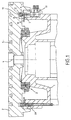
- a universal milling and Drilling machine contains a e.g. run as table slide or console edition 1, on which a table top 2 is designed as an axial angular contact ball bearing Bearing assembly 3 is mounted rotatably about a vertical axis of rotation 4.
- the Table top 2 has on its top several T-shaped flutes 5 for the Clamping of workpieces.
- the table top 2 can be used for clamping of Workpieces should also be provided with threaded bushes.
- the rotary drive of Table top 2 can by a arranged within the support 1 drive motor take place, which is not shown in Fig. 1.
- the support 1 includes a concentric with the axis of rotation 4 outer ring surface 6, on the one in Fig. 2 in perspective Clamping ring 7 with several uniformly distributed over its circumference clamping elements in the form of two spaced apart and opposite each other in the radial direction elastically flexible inner and outer ring segments 8 and 9 is attached.
- the relatively thin-walled ring segments 8 and 9 are at one upper annular surface 10 of the clamping ring 7 integrally formed in the axial direction above and engage in a concentric with the underside of the table top 2 to the rotation axis 4 arranged annular groove 11 a.
- each six inner and outer ring segments 8 and 9 is a coaxial to the clamping ring 7 and in Axial direction displaceable conical pressure ring 12 with oppositely inclined inner and outer conical surfaces 13 and 14 for the pressure of the radial compliant ring segments 8 and 9 arranged on the side walls of the annular groove 11.
- This will be a frictional connection reached between the support 1 and the table top 2, the rotation the tabletop 2 prevents.
- the ring segments return by themselves again a starting position back in between the ring segments and the walls the annular groove only a slight friction or a game exists.
- the hydraulic cylinders 19 are arranged as shown in FIG. 3 such that their piston rods 20 each with one between the ring segments 8 and 9 in the Clamping ring 7 provided through hole 21 and a corresponding Through hole 22 in the pressure ring 12 are aligned.
- Through the through holes 21 in the secured by screws 23 on the support 1 clamping ring. 7 are threaded bolts 24 out, which with its upper part via a nut 25 at fixed to the pressure ring 12 and with its lower part in a threaded bore 26th screwed into the piston rod 20 and secured by a lock nut 27 are.
- Fig. 1 Within the edition 1 is shown in Fig. 1 on the left side limit switch 28 arranged, the 12 when tightening the pressure ring to the support. 1 is pressed. This allows a review of the clamping or release position of the Pressure ring 12 done.
- clamping device may e.g. also for releasably fixing a swivel milling head or other rotary and Swivel devices of a machine tool can be used.
Description
Die Erfindung betrifft eine Dreh- oder Schwenkeinrichtung einer Werkzeugmaschine, insbesondere einen NC-Rundtisch, mit einem auf einer Auflage verdrehoder verschwenkbar gelagerten Maschinenteil und einer Klemmvorrichtung zur lösbaren Fixierung des Maschinenteils in gewünschten Winkelstellungen. Siehe, zum Beispiel, US 5 918 510.The invention relates to a turning or pivoting device of a machine tool, in particular an NC rotary table, with a twisted on a support or pivotally mounted machine part and a clamping device for releasable fixing of the machine part in desired angular positions. See, for example, US 5,918,510.
Zur Durchführung einer Mehrachsbearbeitung in einer einzigen Aufspannung werden bei modernen Bearbeitungszentren und Universal-Fräs- und Bohrmaschinen vielfach numerisch gesteuerte Dreh- oder Schwenkrundtische eingesetzt. So kann z.B. mit den gesteuerten Linearachsen der Maschine sowie der Schwenk- und Drehachse eines NC-Schwenkrundtisches eine 5-Achsen-Bearbeitung auch komplex geformter Werkstücke in einer einzigen Aufspannung durchgeführt werden, wobei Zeit- und Genauigkeitsverluste durch wiederholtes Umspannen der Werkstücke entfallen. Dreh- und Schwenkrundtische müssen jedoch zur Durchführung bestimmter Bearbeitungsoperationen in gewünschten Dreh- oder Winkelstellungen fixierbar sein. Dies kann z.B. über eine Lageregelung der Antriebsmotoren für die Schwenk- bzw. Drehbewegung der Tischplatte erfolgen. Dabei muß von den Antriebsmotoren jedoch ein relativ großes Haltemoment zur Verfügung gestellt werden, damit die Tischplatte trotz der z.B. bei einer Schruppbearbeitung möglichen hohen Kräfte gegen Verdrehung gesichert ist. Hierzu müssen die Antriebsmotoren in der Regel entsprechend groß dimensioniert sein.For performing a multi-axis machining in a single clamping are used in modern machining centers and universal milling and boring machines often numerically controlled rotary or swivel rotary tables used. So can e.g. with the controlled linear axes of the machine as well as the swivel and Rotary axis of a NC swivel rotary table 5-axis machining also complex formed workpieces are carried out in a single clamping, whereby time and accuracy losses by repeated re-clamping of the workpieces omitted. However, rotary and swivel rotary tables must be carried out certain machining operations in desired rotational or angular positions be fixable. This can e.g. via a position control of the drive motors for the Pivoting or rotary movement of the table top done. It must from the drive motors However, a relatively large holding moment can be provided so that the tabletop, despite the e.g. possible during roughing high forces against rotation is ensured. For this purpose, the drive motors usually be sized accordingly large.
Es wurden daher bereits Dreh- bzw. Schwenktische vorgeschlagen, bei denen die auf einer Konsole drehbar gelagerte Tischplatte zur Verdrehsicherung über eine gesonderte Klemmeinrichtung gegen die Konsole gezogen wird. Hierzu wurden hydraulisch verstellbare Zugelemente eingesetzt, die in eine T-förmige Ringnut an der Unterseite der Tischplatte eingreifen und die Tischplatte zur verdrehgesicherten Halterung mit ihrer Unterseite an eine entsprechende Gegenfläche der Konsole ziehen. Der Nachteil dieser Lösung besteht allerdings darin, daß die Tischplatte durch den Anzug auf die Konsole abgesenkt und u.U. auch verformt wird, was zu Ungenauigkeiten bei der Bearbeitung führen kann. Darüber hinaus wird bei jedem Anzug der Tischplatte auf die Konsole auch die Lagerung des Tischplatte erheblich belastet, was zu vorzeitigen Verschleißerscheinungen fuhren kann.Therefore, there have already been proposed rotary or swivel tables in which the on a console rotatably mounted table top to prevent rotation over a separate clamping device is pulled against the console. For this purpose were hydraulically adjustable tension elements used in a T-shaped groove engage the underside of the table top and the table top to prevent rotation Holder with its underside to a corresponding counter surface of the console pull. The disadvantage of this solution, however, is that the table top lowered by the suit on the console and u.U. is also deformed, what to Inaccuracies in editing may result. In addition, each one will Suit the table top on the console also the storage of the table top considerably loaded, which can lead to premature wear and tear.
Aufgabe der Erfindung ist es, eine Dreh- oder Schwenkeinrichtung der eingangs genannten Art zu schaffen, die eine sichere Fixierung des verdreh- oder verschwenkbaren Maschinenteils auch ohne Lageveränderungen ermöglicht.The object of the invention is to provide a rotary or pivoting device of the above mentioned type to create a secure fixation of the rotatable or pivotable Machine part also possible without changes in position.
Diese Aufgabe wird erfindungsgemäß dadurch gelöst, daß die Klemmvorrichtung ein an der Auflage angeordnetes Klemmteil mit seitlich nachgiebigen Klemmelementen zum Eingriff in eine Ringnut an dem verdreh- oder verschwenkbaren Maschinenteil und ein gegenüber dem Klemmteil bewegbares Andruckteil zum Anpressen der Klemmelemente an mindestens eine Seitenwand der Ringnut aufweist.This object is achieved in that the clamping device a clamping part arranged on the support with laterally yielding clamping elements for engagement in an annular groove on the rotatable or pivotable machine part and a relative to the clamping part movable pressing member for pressing the clamping elements has on at least one side wall of the annular groove.
Bei der erfindungsgemäßen Dreh- oder Schwenkeinrichtung erfolgt die Klemmung des auf einer Auflage verdreh- oder verschwenkbar gelagerten Maschinenteils nur über radiale Klemmkräfte, die zu keinem Anzug des Maschinenteils an die Auflage führen. Bei einem Drehtisch mit horizontaler Tischplatte kann z.B. durch die radiale Klemmung eine Absenkung oder Verformung der Tischplatte und eine dadurch bedingte Bearbeitungsungenauigkeit vermieden werden.In the rotary or pivoting device according to the invention, the clamping takes place of the rotatably mounted on a support or pivotally mounted machine part only via radial clamping forces, which do not contribute to a suit of the machine part lead the edition. In a turntable with a horizontal tabletop, e.g. by the radial clamping lowering or deformation of the table top and a resulting inaccuracies are avoided.
Vorteilhafte Ausgestaltungen der Erfindung sind in den Unteransprüchen angegeben.Advantageous embodiments of the invention are specified in the subclaims.
So ist das Klemmteil in einer besonders zweckmäßigen Ausführung ein an der Auflage befestigbarer Klemmring mit gleichmäßig über den Umfang verteilten inneren und äußeren Klemmelementen, die durch das Andruckteil an die innere und äußere Seitenwand der Ringnut anpreßbar sind. Die auf die innere und äußere Seitenwand der Ringnut wirkenden Radialkräfte heben sich gegenseitig auf, so daß sich bei einer Klemmung auch keine seitliche Verschiebung des dreh- bzw. schwenkbaren Maschinenteils gegenüber der Auflage ergibt.Thus, the clamping part in a particularly advantageous embodiment of the on Pad fastenable clamping ring with evenly distributed over the circumference inner and outer clamping elements, by the pressure member to the inner and outer side wall of the annular groove can be pressed. The on the inner and outer Side wall of the annular groove acting radial forces cancel each other, so that at a clamping and no lateral displacement of the rotary or pivotable machine part relative to the edition results.
Ein auch über eine größere Fläche gleichmäßiger Anpreßdruck kann in einer weiteren vorteilhaften Ausführung dadurch erreicht werden, daß die Klemmelemente in Radialrichtung elastisch biegsame Ringsegmente sind. An even over a larger area uniform contact pressure can in another advantageous embodiment can be achieved in that the clamping elements in the radial direction elastically flexible ring segments are.
In einer weiteren zweckmäßigen Ausführung ist das Andruckteil als ein zwischen den inneren und äußeren Klemmelementen angeordneter Konusring mit konischen Andruckflächen ausgebildet. Durch die keil- bzw. konusförmige Ausgestaltung des Andruckteils ist eine Krafterhöhung von den Axial- in die Radialspannkräfte erreichbar.In a further advantageous embodiment, the pressure member is as an intermediate the inner and outer clamping elements arranged conical ring with conical Formed contact surfaces. By the wedge or cone-shaped design the pressure part is an increase in force from the axial to the radial clamping forces reachable.
Die Ringnut und das zugehörige Klemmteil sind in vorteilhafter Weise im Bereich des Außenumfangs des verdreh- oder verschwenkbaren Maschinenteils angeordnet. Dadurch kann auch mit vergleichsweise geringen Klemmkräften ein relativ hohes Haltemoment erzeugt werden.The annular groove and the associated clamping part are advantageously in the range arranged on the outer periphery of the rotatable or pivotable machine part. As a result, even with relatively low clamping forces a relative high holding torque can be generated.
Die Axialverstellung des Andruckteils erfolgt in einer einfach zu steuernden Ausführung durch eine druckmittelbetätigte Kolben-Zylinder-Anordnung, die z.B. mehrere über den Umfang gleichmäßig verteilte Hydraulikzylinder enthält. Das Andruckteil kann aber auch durch andere geeignete Stellantriebe verstellbar sein.The axial adjustment of the pressure element is carried out in an easy-to-control design by a fluid-operated piston-and-cylinder arrangement, e.g. contains several evenly distributed over the circumference hydraulic cylinder. The But pressure part can also be adjusted by other suitable actuators.
Weitere Besonderheiten und Vorzüge der Erfindung ergeben sich aus der folgenden Beschreibung eines bevorzugten Ausführungsbeispiels anhand der Zeichnungen. Es zeigt:
- Fig. 1
- eine Teilansicht eines erfindungsgemäßen NC-Rundtisches einer Werkzeugmaschine mit Klemmvorrichtung im Schnitt; und
- Fig. 2
- eine perspektivische Ansicht eines Klemm- und Gegenrings der in Fig. 1 gezeigten Klemmvorrichtung; und
- Fig. 3
- eine Teilansicht der Klemmvorrichtung im Schnitt.
- Fig. 1
- a partial view of an NC rotary table according to the invention a machine tool with clamping device in section; and
- Fig. 2
- a perspective view of a clamping and counter ring of the clamping device shown in Figure 1; and
- Fig. 3
- a partial view of the clamping device in section.
Der in Fig. 1 schematisch dargestellte NC-Rundtisch einer Universal-Fräs- und
Bohrmachine enthält eine z.B. als Tischschlitten oder Konsole ausgeführte Auflage
1, auf der eine Tischplatte 2 über eine als Axial-Schrägkugellager ausgeführte
Lageranordnung 3 um eine vertikale Drehachse 4 verdrehbar gelagert ist. Die
Tischplatte 2 weist auf ihrer Oberseite mehrere T-förmige Spannuten 5 für die
Aufspannung von Werkstücken auf. Die Tischplatte 2 kann zur Aufspannung von
Werkstücken auch mit Gewindebuchsen versehen sein. Der Drehantrieb der
Tischplatte 2 kann durch einen innerhalb der Auflage 1 angeordneten Antriebsmotor
erfolgen, der in Fig. 1 nicht dargestellt ist.The illustrated in Fig. 1 NC rotary table a universal milling and
Drilling machine contains a e.g. run as table slide or console edition
1, on which a
Wie aus Fig. 1 hervorgeht, enthält die Auflage 1 eine zur Drehachse 4 konzentrische
äußere Ringfläche 6, auf der ein in Fig. 2 perspektivisch dargestellter
Klemmring 7 mit mehreren über dessen Umfang gleichmäßig verteilten Klemmelementen
in Form von jeweils zwei einander beabstandet gegenüberliegenden und
in Radialrichtung elastisch biegsamen inneren und äußeren Ringsegmenten 8 und
9 befestigt ist. Die relativ dünnwandigen Ringsegmente 8 bzw. 9 sind an einer
oberen Ringfläche 10 des Klemmrings 7 in Axialrichtung vorstehend angeformt
und greifen in eine an der Unterseite der Tischplatte 2 zur Drehachse 4 konzentrisch
angeordnete Ringnut 11 ein. Zwischen den gemäß Fig. 2 jeweils sechs inneren
und äußeren Ringsegmenten 8 und 9 ist ein zum Klemmring 7 koaxialer und in
Axialrichtung verschiebbarer konischer Andruckring 12 mit entgegengesetzt geneigten
inneren und äußeren Konusflächen 13 und 14 zum Andruck der radial
nachgiebigen Ringsegmente 8 und 9 an die Seitenwände der Ringnut 11 angeordnet.As is apparent from Fig. 1, the support 1 includes a concentric with the axis of rotation 4
Wie besonders aus Fig. 3 hervorgeht, weist der Andruckring 12 im Bereich der
Konusflächen 13 und 14 einen zu seiner Oberseite hin kontinuierlich zunehmenden
Außendurchmesser und einen entsprechend abnehmenden Innendurchmesser
auf. Mit seinen inneren und äußeren Konusflächen 12 und 13 liegt der Andruckring
12 derart an entsprechenden Vorsprüngen 15 bzw. 16 an der Innenseite der
inneren und äußeren Ringsegmente 8 und 9 an, daß die relativ dünnwandigen und
in Radialrichtung elastisch biegsamen Ringsegmente 8 und 9 bei einer Axialverschiebung
des Andruckrings 12 in Richtung des Klemmrings 7 radial an die inneren
und äußeren Seitenwände 17, 18 der Ringnut 10 angedrückt werden, wie dies
durch die Pfeile verdeutlicht ist. Dadurch wird eine reibkraftschlüssige Verbindung
zwischen der Auflage 1 und der Tischplatte 2 erreicht, die eine Verdrehung
der Tischplatte 2 verhindert. Bei einer vom Klemmring 7 weg gerichteten Axialverschiebung
des Andruckrings 12 kehren die Ringsegmente von selbst wieder in
eine Ausgangsstellung zurück, in der zwischen den Ringsegmenten und den Wandungen
der Ringnut nur eine geringe Reibung oder ein Spiel besteht. As can be seen particularly from Fig. 3, the
Zur Axialverschiebung des Andruckrings 12 sind in der Auflage 1 sechs in Umfangsrichtung
gleichmäßig beabstandete Hydraulikzylinder 19 angeordnet, von
denen nur einer auf der rechten Seite von Fig. 1 dargestellt ist.For axial displacement of the
Die Hydraulikzylinder 19 sind gemäß Fig. 3 derart angeordnet, daß deren Kolbenstangen
20 mit jeweils einer zwischen den Ringsegmenten 8 und 9 in dem
Klemmring 7 vorgesehenen Durchgangsbohrung 21 und einer entsprechenden
Durchgangsbohrung 22 im Andruckring 12 fluchten. Durch die Durchgangsbohrungen
21 in dem über Schrauben 23 auf der Auflage 1 befestigten Klemmring 7
sind Gewindebolzen 24 geführt, die mit ihrem oberen Teil über eine Mutter 25 an
dem Andruckring 12 fixiert und mit ihren unteren Teil in eine Gewindebohrung 26
in der Kolbenstange 20 eingeschraubt und durch eine Kontermutter 27 gesichert
sind.The
Durch entsprechende Ansteuerung der Hydraulikzylinder 19 kann der Andruckring
12 über die Gewindebolzen 24 in eine untere Klemmstellung bewegt werden,
in der er die Ringsegmente 8 und 9 an die Innen- und Außenwand 17, 18 der
Ringnut 11 andrückt. Über die Hydraulikzylinder 19 kann der Andruckring 12
auch in eine obere Lösestellung verschoben werden, wobei die elastischen
Ringsegmente 8, 9 in eine nicht geklemmte Ausgangsstellung zurückkehren.By appropriate control of the
Innerhalb der Auflage 1 ist ein in Fig. 1 auf der linken Seite dargestellter Endschalter
28 angeordnet, der beim Anziehen des Andruckrings 12 an die Auflage 1
betätigt wird. Dadurch kann eine Überprüfung der Klemm- oder Lösestellung des
Andruckrings 12 erfolgen.Within the edition 1 is shown in Fig. 1 on the left
Die Erfindung ist nicht auf das in der Beschreibung erläuterte und in den Figuren dargestellte Ausführungsbeispiel beschränkt. So kann die Klemmvorrichtung z.B. auch zur lösbaren Fixierung eines Schwenkfräskopfs oder anderer Dreh- und Schwenkeinrichtungen einer Werkzeugmaschine eingesetzt werden.The invention is not explained in the description and in the figures illustrated embodiment limited. Thus, the clamping device may e.g. also for releasably fixing a swivel milling head or other rotary and Swivel devices of a machine tool can be used.
Claims (7)
- A rotating or pivoting device in a machine tool, particularly an NC round table withcharacterised in that the clamping device (7, 12) comprises a clamping part (7) disposed on the support (1) and having laterally resilient clamping elements (8, 9) for engagement in an annular groove (11) on the machine part (2) and a pressure application part (12) movable relatively to the clamping part (7) for pressing the clamping elements (8, 9) against at least one side wall of the annular groove (11).a machine part (2) mounted rotatably or pivotally on a support (1) anda clamping device (7, 12) for releasably fixing the machine part (2) in required angle positions,
- A rotary or pivoting device according to claim 1, characterised in that the clamping part is a clamping ring (7) fixable on the support (7) and having inner and outer clamping elements (8, 9) which are distributed uniformly over its periphery and which are pressable by the pressure application part (12) against the inner and outer side wall (17, 18) of the annular groove (11).
- A rotary or pivoting device according to claim 1 or 2, characterised in that the clamping elements (8, 9) are ring segments which are elastically flexible in the radial direction.
- A rotary or pivoting device according to claim 2 or 3, characterised in that the pressure application part (12) is a pressure application ring which is disposed between the inner and outer clamping elements (8, 9) and which has conical side surfaces (13, 14).
- A rotary or pivoting device according to any one of claims 1 to 4, characterised in that the annular groove (11) and the clamping part (7) are disposed in the region of the outer periphery of the rotatable or pivotable machine part (2).
- A rotary or pivoting device according to any one of claims 1 to 5, characterised in that the pressure application part (12) is adjustable in the axial direction by a pressure medium actuated piston and cylinder arrangement (19).
- A rotary or pivoting device according to any one of claims 1 to 6, characterised in that a device (28) for monitoring a clamping or release position of the pressure application part (12) is disposed in the support (1).
Applications Claiming Priority (2)
| Application Number | Priority Date | Filing Date | Title |
|---|---|---|---|
| DE19946424 | 1999-09-28 | ||
| DE19946424A DE19946424A1 (en) | 1999-09-28 | 1999-09-28 | Rotating or swiveling device of a machine tool |
Publications (3)
| Publication Number | Publication Date |
|---|---|
| EP1088616A2 EP1088616A2 (en) | 2001-04-04 |
| EP1088616A3 EP1088616A3 (en) | 2002-05-22 |
| EP1088616B1 true EP1088616B1 (en) | 2005-01-19 |
Family
ID=7923559
Family Applications (1)
| Application Number | Title | Priority Date | Filing Date |
|---|---|---|---|
| EP00120215A Expired - Lifetime EP1088616B1 (en) | 1999-09-28 | 2000-09-25 | Rotating or pivoting device in a machine tool |
Country Status (5)
| Country | Link |
|---|---|
| US (1) | US6457383B1 (en) |
| EP (1) | EP1088616B1 (en) |
| JP (1) | JP4731665B2 (en) |
| DE (2) | DE19946424A1 (en) |
| ES (1) | ES2235727T3 (en) |
Cited By (1)
| Publication number | Priority date | Publication date | Assignee | Title |
|---|---|---|---|---|
| CN103878599A (en) * | 2014-03-28 | 2014-06-25 | 芜湖恒升重型机床股份有限公司 | Locating device and locating method for rotary working table |
Families Citing this family (36)
| Publication number | Priority date | Publication date | Assignee | Title |
|---|---|---|---|---|
| JP3771185B2 (en) | 2002-04-02 | 2006-04-26 | 株式会社エムアイシー | Swivel device |
| DE10319139A1 (en) * | 2003-04-28 | 2004-11-18 | Grob-Werke Burkhart Grob E.K. | Method for securing a rotating workpiece table with profiled locking grips pressed into a correspondingly shaped braking groove around the outside of the table |
| DE10332424B4 (en) * | 2003-07-16 | 2006-04-06 | Peiseler Gmbh & Co. Kg | Rotary table |
| DE10358943A1 (en) † | 2003-12-15 | 2005-07-14 | Fertigungstechnik Weissenfels Gmbh | Worktable |
| ES2328255T3 (en) | 2005-09-16 | 2009-11-11 | Zf Friedrichshafen Ag | ELECTRIC SWITCH |
| DE102005061613B4 (en) * | 2005-12-21 | 2007-10-04 | Ehinger Giesserei Und Werkzeugmaschinenfabrik Gmbh | Machine tool for machining gears |
| US20080047120A1 (en) * | 2006-08-24 | 2008-02-28 | Hardinge, Inc. | Rotary table with frameless motor |
| JP5152896B2 (en) * | 2007-10-10 | 2013-02-27 | 津田駒工業株式会社 | Rotary indexing device in machine tools |
| JP5216528B2 (en) * | 2008-10-24 | 2013-06-19 | 津田駒工業株式会社 | Clamping device in an indexing device for machine tools |
| DE102008021238B4 (en) | 2008-04-28 | 2018-09-13 | Imo Holding Gmbh | Machine tool for machining a toothing in the inside of an annular workpiece |
| JP5286047B2 (en) | 2008-11-19 | 2013-09-11 | 津田駒工業株式会社 | Clamping device in spindle drive for machine tool |
| US8770065B2 (en) | 2009-11-05 | 2014-07-08 | Colonial Tool Group Inc. | Rotary workpiece indexing method and apparatus |
| CN101941154A (en) * | 2010-10-14 | 2011-01-12 | 无锡立达齿轮制造有限公司 | Vertical lathe rotary table |
| CN102454729A (en) * | 2010-10-25 | 2012-05-16 | 财团法人工业技术研究院 | Power-off brake device |
| CN102062285B (en) * | 2010-11-19 | 2012-08-08 | 山东大学 | Large precise differential dynamic and static pressure rotary table |
| TWI438052B (en) * | 2011-10-17 | 2014-05-21 | Ind Tech Res Inst | Braking device |
| CN102581664A (en) * | 2012-03-16 | 2012-07-18 | 华北水利水电学院 | Gear and rack type long shaft part multi-keyway milling fixture |
| JP5607690B2 (en) * | 2012-08-01 | 2014-10-15 | ファナック株式会社 | Machine tool with rotating table |
| CN103213002B (en) * | 2013-04-11 | 2018-01-09 | 黑旋风锯业股份有限公司 | A kind of static pressure supporting rotary workbench |
| CN103878509A (en) * | 2014-03-17 | 2014-06-25 | 创美工艺(常熟)有限公司 | Workpiece clamping rotating table structure matched with welding robots |
| CN104097089B (en) * | 2014-05-19 | 2016-12-07 | 山东鲁南华源数控股份有限公司 | Rotary table hydraulic clamp |
| JP5855706B2 (en) * | 2014-06-16 | 2016-02-09 | ファナック株式会社 | Machine tool with rotating table |
| CN104353958B (en) * | 2014-10-27 | 2016-05-04 | 迈赫机器人自动化股份有限公司 | Fine positioning turntable |
| TWI562855B (en) * | 2014-11-19 | 2016-12-21 | Ind Tech Res Inst | Clamping-positioning device and operating method thereof |
| JP6559455B2 (en) * | 2015-04-06 | 2019-08-14 | 株式会社北川鉄工所 | Clamping device |
| DE102015224860A1 (en) * | 2015-12-10 | 2017-03-16 | Schaeffler Technologies AG & Co. KG | Rotary table bearing arrangement |
| DE102015224865A1 (en) * | 2015-12-10 | 2017-03-09 | Schaeffler Technologies AG & Co. KG | Rotary table bearings |
| CA3037001C (en) * | 2016-09-22 | 2021-04-13 | Nexen Group, Inc. | Modular zero backlash default to lock brake/locking apparatus |
| WO2018210932A1 (en) * | 2017-05-17 | 2018-11-22 | Deckel Maho Pfronten Gmbh | Device for clamping a rotatably mounted shaft element, in particular for use on a machine tool, and axis structure of a machine tool |
| DE102017214362A1 (en) | 2017-05-17 | 2018-11-22 | Deckel Maho Pfronten Gmbh | DEVICE FOR TERMINATING A ROTATELY BASED WAVELENEMENTS, ESPECIALLY FOR USE IN A MACHINE MACHINE, AND AXLE ASSEMBLY OF A TOOLING MACHINE |
| CN107378526A (en) * | 2017-08-10 | 2017-11-24 | 南通第五机床有限公司 | A kind of nC vertical milling machine workbench |
| DE102019106088A1 (en) * | 2019-03-11 | 2020-09-17 | Starrag Gmbh | Clamping system for a machine tool |
| KR102201426B1 (en) * | 2019-05-02 | 2021-01-11 | 최우혁 | Index-tilting device for bic merterial |
| CN110883566B (en) * | 2019-12-25 | 2021-04-06 | 郑州大学 | Simple and easy merry go round machine workstation main shaft structure |
| CN114310362A (en) * | 2022-01-18 | 2022-04-12 | 苏州明志科技股份有限公司 | Locking mechanism and servo revolving stage |
| DE102022117967A1 (en) * | 2022-07-19 | 2024-01-25 | Schaeffler Technologies AG & Co. KG | Rotary table bearing arrangement |
Family Cites Families (11)
| Publication number | Priority date | Publication date | Assignee | Title |
|---|---|---|---|---|
| US3786721A (en) * | 1971-09-09 | 1974-01-22 | Prod Machine Co | Clamp for rotary tables |
| NL7512471A (en) * | 1974-11-05 | 1976-05-07 | Heinz Ditzel En Werner Ditzel | ROLLLY ADJUSTABLE SPINDLE INCLUDED, TOOL-BEARING PART HEAD FOR AS FINE AS POSSIBLE OPERATING WORKPIECES ON TOOL MACHINES SUCH AS ERODER MACHINES, GRINDER, MILLER-OPERATING MACHINES AND MILLING MACHINES. |
| US4380939A (en) * | 1980-07-01 | 1983-04-26 | Cameron Iron Works, Inc. | Rotary indexing table |
| JP2553848B2 (en) * | 1986-11-18 | 1996-11-13 | 三井精機工業株式会社 | Clamping device for indexing table |
| JPS63288607A (en) * | 1987-05-20 | 1988-11-25 | Mitsubishi Heavy Ind Ltd | Device for fixing tailstock spindle to tailstock main unit |
| JPH0367068U (en) * | 1989-11-06 | 1991-06-28 | ||
| US5450771A (en) * | 1993-06-16 | 1995-09-19 | Utica Enterprises, Inc. | Rotary index table assembly |
| JPH08150542A (en) * | 1994-11-25 | 1996-06-11 | Nippon Koshuha Kogyo Kk | Indexing device |
| JPH1029125A (en) * | 1996-07-15 | 1998-02-03 | Toyoda Mach Works Ltd | Rotational dividing device |
| JP3817599B2 (en) * | 1997-07-04 | 2006-09-06 | 大阪機工株式会社 | Pallet clamp device |
| DE19840942C1 (en) * | 1998-09-08 | 2000-03-09 | Albeck Gmbh | Multiple clamping device |
-
1999
- 1999-09-28 DE DE19946424A patent/DE19946424A1/en not_active Withdrawn
-
2000
- 2000-09-25 ES ES00120215T patent/ES2235727T3/en not_active Expired - Lifetime
- 2000-09-25 DE DE50009265T patent/DE50009265D1/en not_active Expired - Lifetime
- 2000-09-25 EP EP00120215A patent/EP1088616B1/en not_active Expired - Lifetime
- 2000-09-27 JP JP2000293868A patent/JP4731665B2/en not_active Expired - Fee Related
- 2000-09-27 US US09/670,976 patent/US6457383B1/en not_active Expired - Lifetime
Cited By (1)
| Publication number | Priority date | Publication date | Assignee | Title |
|---|---|---|---|---|
| CN103878599A (en) * | 2014-03-28 | 2014-06-25 | 芜湖恒升重型机床股份有限公司 | Locating device and locating method for rotary working table |
Also Published As
| Publication number | Publication date |
|---|---|
| US6457383B1 (en) | 2002-10-01 |
| DE19946424A1 (en) | 2001-04-05 |
| EP1088616A2 (en) | 2001-04-04 |
| JP2001113425A (en) | 2001-04-24 |
| EP1088616A3 (en) | 2002-05-22 |
| DE50009265D1 (en) | 2005-02-24 |
| JP4731665B2 (en) | 2011-07-27 |
| ES2235727T3 (en) | 2005-07-16 |
Similar Documents
| Publication | Publication Date | Title |
|---|---|---|
| EP1088616B1 (en) | Rotating or pivoting device in a machine tool | |
| DE19641831B4 (en) | Universal milling and drilling machine | |
| DE2042344C3 (en) | Tapping chucks | |
| DE4339754C1 (en) | Device for making bores in a dish or a rim of a motor-vehicle wheel | |
| DE3610671C2 (en) | ||
| EP1058593B1 (en) | Hexapod machining centre | |
| EP2072201B1 (en) | Edge scanner | |
| EP3093088B1 (en) | Workpiece clamping device including a face driver | |
| DE1527181B1 (en) | TAPPING MACHINE | |
| DE2908422C2 (en) | Honing or lapping head | |
| WO1987004959A1 (en) | Adjustable tool-holder in machine-tools for slot milling | |
| DE102011089462A1 (en) | Finishing machine i.e. honing machine, for e.g. finishing hole in workpiece for hone, has machine-side setting element coupled with tool-side setting elements, where tool-side setting elements are decoupled from machine-side setting element | |
| DE69938597T2 (en) | processing head | |
| DE4019671C2 (en) | ||
| EP2805785B1 (en) | Tool holder for machine tools | |
| EP0545006A1 (en) | Tool turret | |
| EP0933154A2 (en) | Facing-toolhead | |
| DE19533730A1 (en) | Clearing device and method for clearing | |
| DE3446826A1 (en) | JAW CHUCK FOR LATHE TO MACHINE WORKPIECES UNDER SEVERAL MACHINING AXES | |
| EP0038103B1 (en) | Quick-change chuck | |
| DE820825C (en) | Automatic driver | |
| DE3702564C2 (en) | Drilling head for internal contour machining of hollow cylindrical workpieces | |
| WO1988005359A1 (en) | Device for joining two components essentially dynamically balanced in the joining zone, in particular a tool head with a tool holder in machine-tools | |
| DE2260106A1 (en) | ADDITIONAL EQUIPMENT FOR METAL DRILLING MACHINES | |
| EP1136160A1 (en) | Work piece holding device |
Legal Events
| Date | Code | Title | Description |
|---|---|---|---|
| PUAI | Public reference made under article 153(3) epc to a published international application that has entered the european phase |
Free format text: ORIGINAL CODE: 0009012 |
|
| AK | Designated contracting states |
Kind code of ref document: A2 Designated state(s): AT BE CH CY DE DK ES FI FR GB GR IE IT LI LU MC NL PT SE |
|
| AX | Request for extension of the european patent |
Free format text: AL;LT;LV;MK;RO;SI |
|
| RAP1 | Party data changed (applicant data changed or rights of an application transferred) |
Owner name: DECKEL MAHO PFRONTEN GMBH |
|
| PUAL | Search report despatched |
Free format text: ORIGINAL CODE: 0009013 |
|
| AX | Request for extension of the european patent |
Free format text: AL;LT;LV;MK;RO;SI |
|
| 17P | Request for examination filed |
Effective date: 20021112 |
|
| AKX | Designation fees paid |
Designated state(s): CH DE ES FR GB IT LI |
|
| GRAP | Despatch of communication of intention to grant a patent |
Free format text: ORIGINAL CODE: EPIDOSNIGR1 |
|
| GRAP | Despatch of communication of intention to grant a patent |
Free format text: ORIGINAL CODE: EPIDOSNIGR1 |
|
| GRAS | Grant fee paid |
Free format text: ORIGINAL CODE: EPIDOSNIGR3 |
|
| GRAA | (expected) grant |
Free format text: ORIGINAL CODE: 0009210 |
|
| AK | Designated contracting states |
Kind code of ref document: B1 Designated state(s): CH DE ES FR GB IT LI |
|
| REG | Reference to a national code |
Ref country code: GB Ref legal event code: FG4D Free format text: NOT ENGLISH |
|
| REG | Reference to a national code |
Ref country code: CH Ref legal event code: NV Representative=s name: MICHELI & CIE INGENIEURS-CONSEILS Ref country code: CH Ref legal event code: EP |
|
| GBT | Gb: translation of ep patent filed (gb section 77(6)(a)/1977) |
Effective date: 20050119 |
|
| REG | Reference to a national code |
Ref country code: IE Ref legal event code: FG4D Free format text: GERMAN |
|
| REF | Corresponds to: |
Ref document number: 50009265 Country of ref document: DE Date of ref document: 20050224 Kind code of ref document: P |
|
| REG | Reference to a national code |
Ref country code: ES Ref legal event code: FG2A Ref document number: 2235727 Country of ref document: ES Kind code of ref document: T3 |
|
| PLBE | No opposition filed within time limit |
Free format text: ORIGINAL CODE: 0009261 |
|
| STAA | Information on the status of an ep patent application or granted ep patent |
Free format text: STATUS: NO OPPOSITION FILED WITHIN TIME LIMIT |
|
| ET | Fr: translation filed | ||
| 26N | No opposition filed |
Effective date: 20051020 |
|
| PGFP | Annual fee paid to national office [announced via postgrant information from national office to epo] |
Ref country code: ES Payment date: 20130816 Year of fee payment: 14 Ref country code: DE Payment date: 20130930 Year of fee payment: 14 Ref country code: CH Payment date: 20130821 Year of fee payment: 14 |
|
| PGFP | Annual fee paid to national office [announced via postgrant information from national office to epo] |
Ref country code: GB Payment date: 20130927 Year of fee payment: 14 |
|
| PGFP | Annual fee paid to national office [announced via postgrant information from national office to epo] |
Ref country code: FR Payment date: 20130925 Year of fee payment: 14 |
|
| PGFP | Annual fee paid to national office [announced via postgrant information from national office to epo] |
Ref country code: IT Payment date: 20140915 Year of fee payment: 15 |
|
| REG | Reference to a national code |
Ref country code: DE Ref legal event code: R119 Ref document number: 50009265 Country of ref document: DE |
|
| REG | Reference to a national code |
Ref country code: CH Ref legal event code: PL |
|
| GBPC | Gb: european patent ceased through non-payment of renewal fee |
Effective date: 20140925 |
|
| REG | Reference to a national code |
Ref country code: FR Ref legal event code: ST Effective date: 20150529 |
|
| PG25 | Lapsed in a contracting state [announced via postgrant information from national office to epo] |
Ref country code: DE Free format text: LAPSE BECAUSE OF NON-PAYMENT OF DUE FEES Effective date: 20150401 Ref country code: GB Free format text: LAPSE BECAUSE OF NON-PAYMENT OF DUE FEES Effective date: 20140925 Ref country code: CH Free format text: LAPSE BECAUSE OF NON-PAYMENT OF DUE FEES Effective date: 20140930 Ref country code: LI Free format text: LAPSE BECAUSE OF NON-PAYMENT OF DUE FEES Effective date: 20140930 |
|
| PG25 | Lapsed in a contracting state [announced via postgrant information from national office to epo] |
Ref country code: FR Free format text: LAPSE BECAUSE OF NON-PAYMENT OF DUE FEES Effective date: 20140930 |
|
| REG | Reference to a national code |
Ref country code: ES Ref legal event code: FD2A Effective date: 20151029 |
|
| PG25 | Lapsed in a contracting state [announced via postgrant information from national office to epo] |
Ref country code: ES Free format text: LAPSE BECAUSE OF NON-PAYMENT OF DUE FEES Effective date: 20140926 |
|
| PG25 | Lapsed in a contracting state [announced via postgrant information from national office to epo] |
Ref country code: IT Free format text: LAPSE BECAUSE OF NON-PAYMENT OF DUE FEES Effective date: 20150925 |