EP1087613A2 - Appareil de commande d'impression, appareil d'impression, procédé de commande d'impression, procédé d'impression, support d'enregistrement, et procédé d'établissement d'une table de conversion de couleurs - Google Patents
Appareil de commande d'impression, appareil d'impression, procédé de commande d'impression, procédé d'impression, support d'enregistrement, et procédé d'établissement d'une table de conversion de couleurs Download PDFInfo
- Publication number
- EP1087613A2 EP1087613A2 EP00118911A EP00118911A EP1087613A2 EP 1087613 A2 EP1087613 A2 EP 1087613A2 EP 00118911 A EP00118911 A EP 00118911A EP 00118911 A EP00118911 A EP 00118911A EP 1087613 A2 EP1087613 A2 EP 1087613A2
- Authority
- EP
- European Patent Office
- Prior art keywords
- color
- ink
- dots
- tone data
- printing
- Prior art date
- Legal status (The legal status is an assumption and is not a legal conclusion. Google has not performed a legal analysis and makes no representation as to the accuracy of the status listed.)
- Granted
Links
Images


Classifications
-
- H—ELECTRICITY
- H04—ELECTRIC COMMUNICATION TECHNIQUE
- H04N—PICTORIAL COMMUNICATION, e.g. TELEVISION
- H04N1/00—Scanning, transmission or reproduction of documents or the like, e.g. facsimile transmission; Details thereof
- H04N1/46—Colour picture communication systems
- H04N1/56—Processing of colour picture signals
- H04N1/60—Colour correction or control
- H04N1/6016—Conversion to subtractive colour signals
- H04N1/6022—Generating a fourth subtractive colour signal, e.g. under colour removal, black masking
- H04N1/6025—Generating a fourth subtractive colour signal, e.g. under colour removal, black masking using look-up tables
Definitions
- the present invention relates to technology for image printing on printing media by jetting ink drops of each color ink, and more particularly to technology for the printing of high-quality images in which bronzing does not occur.
- Ink jet printers are widely used as image output devices for machines such as computers. Ink jet printers print color images by forming ink dots in colors such as cyan, magenta, yellow, and black on printing media.
- ink jet printers form images by jetting ink drops of each color on printing media, when the forming density of the ink dots is high, the jetted ink drops mix on printing media, or the printing paper is caused to swell and crease.
- printing paper has a so-called tolerance value for ink, which is the limit beyond which ink dots cannot be formed at higher densities.
- various kinds of specialized printing papers are offered which raise the tolerance value of the ink, thereby reducing the likelihood of the occurrence of these problems.
- By using printing paper specialized for ink jet printers it is possible to print high-quality images without paper cockling or ink feathering.
- specialized papers with even higher performance are offered, such as printing paper on which the surface of the printed image has a gloss finish similar to that of photographs, or printing paper with weatherability on which the printed image does not fade easily.
- Bronzing refers to a phenomenon in which the quality of the light reflected by the surface of the printing paper changes according to the dye of jetted ink drops condensing on the surface of the printing paper, or according to the print surface having a bronze hue depending on the viewing angle due to the distribution of pigment granularity remaining on the print surface because of the difference in the pigment granularity characteristics of each ink.
- Techniques have been developed which offer printing paper on which bronzing does not occur easily (see Japanese Patent Laid-open No. 7-214892 or Japanese Patent Laid-open No. 10-217603, among others). Nevertheless, even by using such specialized paper, it is not possible to print high-quality images using the existing wide varieties of printing paper and still avoid bronzing.
- the present invention aims to solve the above-mentioned problems found in the conventional art, and it is an object of the present invention to provide a technique for printing high-quality images without bronzing by using the existing wide variety of printing papers.
- the print control apparatus of the present invention employs the following constitution.
- the print control method of the present invention is a print control method for controlling a printing portion by sending control information for controlling the formation of dots of appropriate colors by said printing portion, by which a color image corresponding to image data is printed by combining black ink dots and ink dots in a plurality of primary colors capable of producing achromatic color by a combination, said print control method comprising the steps of:
- the above-mentioned print control apparatus and print control method effect conversions by referring to the above color conversion table.
- the color conversion table here is a number chart in which corresponding tone data between the above primary color inks and black ink for each defined multiple color shades are recorded.
- the above-mentioned print control apparatus and print control method judge formation/non-formation of dots in the above primary color inks and black ink based on the tone data acquired in this way, and send the judgment results to the printing portion as the above controlling information. By doing so, it is possible for the reasons presented below to print high-quality images without the occurrence of bronzing.
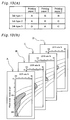
- Fig. 17 is an explanatory figure showing the conditions under which bronzing occurs, and the present invention was completed by discovering the correlation indicated in Fig. 17.
- the exact conditions for the occurrence of bronzing vary somewhat depending on the type of ink and type of printing media used, as well as on the hue of the image to be printed, the following explanation is based on the bronzing conditions described in Fig. 17 to represent the conditions under which bronzing occurs. The following is a discussion of Fig. 17.
- Fig. 17 shows the conditions under which bronzing occurs by assigning black color levels and UCR rates to the vertical and horizontal axes, respectively.
- Black color is an index corresponding to the brightness of the printed image. As the black color level value decreases, the brightness of the image increases. For example, an image in which only black ink dots are formed in every picture element is an image with 100% black color level. Similarly, an image in which only black ink dots are formed in half of the picture elements is an image with 50% black color level. Also, 110% black color level indicates a state in which black ink dots are formed superimposed on 10% of the picture elements on top of black ink dots formed in every picture element.
- the printing portion controlled by the print control apparatus in the present invention comprises a plurality of primary color inks which are capable of expressing achromatic color by using the combination thereof. Therefore, when printing an image of a certain black color level, it is possible to print the image not only with black ink, but also by combining the primary color dots.
- the UCR rate assigned to the horizontal axis in Fig. 17 is an index showing the rate of black ink dots used when printing an image of black color level. For example, a UCR rate of 100% indicates a state in which an image is printed by using only black ink dots. Also, a UCR rate of 50% indicates a state in which half of the dots of black ink dots under 100% UCR state are replaced by a combination of dots of primary color inks.
- the area with hatching in Fig. 17 is the area where bronzing occurs.
- ink duty-factor in the figure is an index corresponding to the ink dot formation density. As the value of the ink duty-factor increases, so too does the ink dot formation density. For example, 100% ink duty-factor indicates a state in which dots are formed in every picture element, and 120% ink duty-factor indicates a state in which dots are formed over-layered in 20% of the picture element on top of dots formed in every picture element.
- an image printed under a printing condition A as shown in Fig. 17, that is, under the condition of a 70% black color level and 90% UCR rate, as an example. Since a printing condition A are within the hatched area, bronzing occurs in images printed under this condition. However, it is possible to avoid bronzing by keeping the black color level but changing the UCR rate from 90% to 80%, since printing is done under another printing condition B, which is outside the area with hatching. Reducing the UCR rate while maintaining the black color level is done by changing a part of black ink dots to a combination of dots of primary color inks.
- the above explanation presupposes varying the printing condition A, in which bronzing occurs, to the printing condition B, in which bronzing does not occur.
- Each printing paper has the defined ink tolerance value, and when the tolerance value is exceeded, printed image quality degrades because of ink feathering or printing paper swelling.
- the ink duty-factor increases if printing conditions are varied toward decreasing the UCR rate.
- Specialized paper on which bronzing is especially likely to occur, has a high ink tolerance value. Therefore, decreasing the UCR rate to avoid bronzing does not lead so far as to the ink tolerance value.
- image data is converted to tone data in which the occurrence of bronzing is confirmed to be unlikely, and controlling information of dots of each color ink generated based on this tone data is sent to the above-mentioned printing portion.
- the printing portion can generate a high-quality image without bronzing.
- image data is first converted to tone data in which the occurrence of bronzing is confirmed to be unlikely, and a color image is printed by forming ink dots of primary color inks and black ink, based on the controlling information of dots for each color ink generated based on this tone data.
- the print control apparatus and print control method of the present invention are suitable because a good image is produced in which bronzing is unlikely to occur.
- the print control apparatus it is possible to store a plurality of color conversion table sets by distinguishing the types of above primary color inks and black ink beforehand, then to select a color conversion table based on the information about the types of the above primary color inks and black ink used for dot formation by the above-mentioned printing portion, and then to convert the above image data by referring to the selected color conversion table.
- Another option is to store a plurality of color conversion table sets by distinguishing the types of printing media on which dots are formed, to select a color conversion table based on the information about the types of printing media on which dots are formed by the above-mentioned printing portion, and then to convert the above image data by referring to the selected color conversion table.
- Yet another option is to store a plurality of color conversion table sets by distinguishing types of the above primary color inks and black ink, and the types of printing media on which dots are formed, to select a color conversion table based on the information about the types of ink used for dot formation and the types of printing media on which dots are formed by the above-mentioned printing portion, and then to convert the above image data by referring to the selected color conversion table.
- the conditions under which bronzing occurs may vary slightly depending on the type of printing ink used. Ink attributes are especially different between so-called dye-type inks and pigment color inks, and the conditions under which bronzing occurs are also different. Moreover, bronzing conditions may vary slightly depending on the type of printing media on which ink dots are formed. Therefore, by selecting a color conversion table corresponding to the type of ink used for dot formation or the type of printing media, and by converting image data referring to the color conversion table thus selected, it is possible to convert color image precisely in accordance with the type of ink and type of printing media. As a result, the above-mentioned print control apparatus is suitable because allows the printing of high-quality images in which bronzing is unlikely to occur.
- Such a print control apparatus can be arranged to send controlling information for dots of each color ink of cyan, magenta, and yellow as controlling information for controlling the formation of ink dots in primary color inks. Moreover, the print control apparatus can be arranged to send controlling information about color dots of each color ink of light cyan with lower intensity than the above cyan, or light magenta with lower intensity than the above magenta.
- the achromatic color can be expressed by combining each ink in cyan, magenta, and yellow, or by combining each ink with the addition of light cyan and light magenta inks to these. Therefore, even when bronzing occurs, it is possible to avoid bronzing by replacing a part of the black ink with cyan, magenta, and yellow ink, or by replacing part of the black ink with light cyan, light magenta, and yellow. Therefore, by first setting the above color conversion table within the range of the combinations of tone data in which the occurrence of bronzing is confirmed to be unlikely, and then converting the image data by referring to this color conversion table, the above print control apparatus is suitable because it permits the printing of high-quality images without bronzing.
- the above-mentioned print control apparatus may be embodied in following manner. That is:
- a print control apparatus for controlling a printing portion by sending control information for controlling the formation of dots of appropriate colors by said printing portion, by which the color image corresponding to the image data is printed by combining black ink dots and ink dots in a plurality of primary colors capable of producing achromatic color by their combination, said print control apparatus comprising:
- the first tone data is converted to the second conversion data so that the total density of ink dots in each color formed on the printing media does not exceed the defined density.
- Such conversion is done by a part of the tone data of the primary color inks expressing the achromatic color in the first tone data into the black ink tone data.
- the total density of ink dots not to exceed the defined density because the achromatic color can be expressed with fewer ink dots in black ink than ink dots in primary color inks.
- the second tone data is converted to the third tone data by converting a part of the black ink tone data to tone data of the primary color inks again. Based on the third tone data thus obtained, the formation or non-formation of dots of these primary color inks and black ink is determined, and this judgment result is output as the above controlling information.
- ink dots of the above primary color inks and black ink are formed based on the output controlling information in this way, it is possible to print high-quality images in which bronzing is unlikely to occur.
- the first index corresponds to the tone data for black ink when the achromatic color in the image data is expressed only by using black ink.
- the second index is an index corresponding to the tone data for black ink in which bronzing begins to occur when expressing the achromatic color indicated by the first index.
- One example is an index corresponding to the UCR rate indicated in Fig. 17.
- tone data corresponding to the type of the ink used in order to store bronzing occurrence conditions as tone data for primary color inks and black ink.
- the above print control apparatus is suitable because it is possible to store the tone data by using less storage space by storing the tone data using the two indices as described above.
- a combination of tone data capable of expressing hues without causing bronzing can be set up, and upon converting the above image data, it is possible to have each process of the said unit for bronzing occurrence conditions storage and the said unit of image data confirmation actually done at the time as image data conversion by conversion with reference to this color conversion table.
- the above print control apparatus is suitable because it enables rapid printing of high-quality images in which bronzing is unlikely to occur if each of these processes are actually performed at time of image data conversion.
- the above version is a method for setting up color conversion tables which are used when converting a color image into tone data for each color: black and the primary colors capable of expressing the achromatic color when combined, and in which the above color image hues and the above tone data for each color are matched and stored, said method comprising the steps of:
- tone data corresponding to the type of the ink used it is necessary to store tone data corresponding to the type of the ink used, in order to store the conditions under which bronzing occurs as tone data of primary color inks and black.
- the above version of conceiving of the current invention is suitable because it is possible to store the tone data by using less storage space by storing the tone data using the two indices as described above.
- the current invention may be conceived of as recording medium in which programs for executing these functions by using a computer is recorded in a format which computers can read. That is, this version of recording medium is a recording medium for recording a method for controlling the above printing portion by sending control information for controlling dot formation of the above colors by the printing portion, which prints the color image corresponding to the image data by combining black ink dots and ink dots in a plurality of primary colors whose combination is capable of producing achromatic color, in a format which computers can read, which stores programs for realizing:
- the current invention is conceived of as program codes that describe programs for realizing controlling method for the above printing portion by sending control information for controlling dot formation of the above colors by the printing portion which prints the color image corresponding to the image data, by combining black ink dots and ink dots in a plurality of primary colors which in combination are capable of producing achromatic color, which describe program codes realizing:
- FIG. 1 is an explanatory figure showing the configuration of the printing system of the current invention including the print control apparatus.
- this printing system is configured with a computer 80 as a print control apparatus and a color printer 20, which, when defined programs are loaded onto the computer and executed, functions as a printing system as a whole.
- Color images which will be printed are scanned in by using a color scanner 21 connected to a computer 80, or images that are created on the computer 80 by various application programs may be used.
- These image data ORG are converted to image data which can be printed by color printer 20, by a CPU 81 in the computer 80.
- Color printer 20 prints a color image which corresponds to the color original by forming ink dots of each color on printing medium, following this image data FNL.
- the computer 80 is configured with a CPU 81, which executes various calculation processes, a RAM 83, which temporarily records data, a ROM 82, which records various programs, and a hard disk 26 and soon. Moreover, the computer 80 can download necessary data and programs from a server SV on an external network onto the hard disk 26, when a SIO 88 is connected to the public telephone line PNT via a modem 24.
- the color printer 20 is a printer which can print color images.
- This embodiment uses an ink jet printer, which prints color images by forming dots of four colors in total: cyan; magenta; yellow; and black, on printing paper. It is certainly possible to use an ink jet printer which can form dots of six colors in total: light cyan dots, which is cyan with lower intensity: and light magenta dots, which is magenta with lower intensity; in addition to the dots of these four colors.
- the ink jet method of the ink jet printer used in this embodiment employs a method which uses piezo elements, as described below. It is also possible to use a printer with a nozzle unit which jets ink in other methods. This approach may, for example, be adapted to a printer which employs the method of ink jet by bubbles which are created in the ink path by applying an electric current to a heater placed in the ink path.
- FIG. 2 is a block figure schematically showing the software configuration of this print control apparatus.
- every application program 91 operates under an operating system.
- a video driver 90 and a printer driver 92 are installed in the operating system, and image data sent out by each application program 91 is sent out to the color printer 20 via these drivers.
- the printer driver 92 on the computer 80 receives image data from the application program 91, executes the defined imaging processes, and converts the image data to image data which can be printed by the printer.
- imaging processes executed by the printer driver 92 are configured with 4 major modules: a resolution conversion module 93; a color conversion module 94; a half tone module 95; and an interlace module 96. The contents of imaging processes executed by each module will be described below.
- Image data received by the printer driver 92 is converted by these modules, and then sent out to the color printer 20 as the final image data FNL.
- the color printer 20 in this embodiment only plays a role of forming dots according to the image data FNL, and does not execute imaging processes. However, it is possible to carry out a part of the image conversion on the color printer 20.
- FIG. 3 shows the configuration summary of the color printer 20 in this embodiment.
- this color printer 20 is configured with a mechanism which jets ink and forms dots by driving a printing head 41 installed in a carriage 40, a mechanism which oscillates this carriage 40 axial to the shaft of a platen 36 by a carriage motor 30, a mechanism which moves printing paper P by means of a paper drive motor 35, and a control circuit 60.
- the mechanism which oscillates the carriage 40 in the axial direction relative to the platen 36 is configured with: a pulley 32, which tensions an endless drive belt 31 between a sliding shaft 33, which sustains the carriage 40, which is built parallel to the shaft of platen 36 capable of sliding; and a position detection censor 34, which detects the default position of the carriage 40 and so on.
- the mechanism for moving the printing paper P is configured with: the platen 36; the paper drive motor 35; a paper feed roller, which is not shown in the figure; and a gear train (not shown), which transmits the rotational motion of the paper drive motor 35 to the platen 36 and the paper feed roller.
- the printing paper P is placed in such a way so that it is inserted between the platen 36 and the paper feed roller, and only a defined amount corresponding to the rotational angle of the platen 36 is sent.
- a PC interface 64 which transfers data between the computer 80; a peripheral input/output component (PIO) 65, which transfers data between the paper drive motor 35; the carriage motor 30; a drive buffer 67, which supplies dot on/off signals to an ink jet head 44 or 47; a CPU 61, which controls them; a RAM 63, which temporarily records data; and so on, are built inside the control circuit 60.
- An oscillator 70 which sends out drive wave, and a distributor 69, which distributes the output from the oscillator 70 to the ink jet head 44 or 47 according to the defined timing, are also built inside the control circuit 60.
- two more lines of ink jet heads are added in the color printer if it is capable of forming dots in total of six colors, light cyan and light magenta in addition to dots of four colors: cyan; magenta; yellow; and black.
- the CPU 61 sends trigger signals to the oscillator 70, and synchronizing to them, the CPU 61 reads out the dot on/off signals stored on the RAM 63 and sends them out to the drive buffer 67.
- the CPU 61 controls the motion of the paper drive motor 35, synchronizing to the motion of the carriage.
- ink dots are formed in the appropriate positions on the printing paper.
- An ink cartridge 42 which stores black (K) ink
- an ink cartridge 43 which stores 3 color inks, cyan (C), magenta (M), and yellow (Y)
- K black
- M magenta
- Y yellow
- Figure 4 is an explanatory figure showing the visual shape of the ink cartridge 42.
- an identification label 56 is pasted on the ink cartridge, on which the type of ink stored in the ink cartridge is written.
- the type of ink is specified by the number written on the identification label 56.
- Figure 5 is an explanatory figure showing an example of compositions of ink stored in the ink cartridges 42, 43.
- Figure 5 (a) shows the composition of so-called dye-type ink, whose ink color is created by dye; and
- Figure 5 (b) shows the composition of the so-called pigment ink.
- each ink is a mixed solution made up by adding the appropriate amount of each of the following to distilled water: dye or pigments for ink coloration; and an organic solvent used as a solvent for the dye or the pigments, as well as for adjusting the ink viscosity.
- various other ink compositions than the compositions shown in Figure 5 can be employed.
- light magenta and light cyan ink use a composition in which the dye concentration is lower than cyan ink or magenta ink.
- each ink inside the cartridges is supplied to the ink jet head 44 or 47 for each color respectively through a pipe which is not shown in the figure.
- the ink which is supplied to each head is jetted in the method explained below and forms dots on the printing paper.
- Figure 6 (a) is an explanatory figure showing the internal structure of the ink head for each color.
- 48 nozzles Nz are set up for each color inside the ink jet head 44 or 47 specified for each color, and an ink path 50, and piezo elements PE along that path, are set up in each nozzle.
- the piezo elements PE are, as is well-known, elements whose crystal structure is distorted by application of voltage, and they render electricity - machine energy conversion at an extremely high speed.
- the piezo elements PE expand during the time period of voltage application, and transform one side of the ink path 50.
- the volume of the ink path 50 flexes according to the expansion of the piezo elements PE, and the amount of ink corresponding to the amount of this erosion is jetted at a high speed as particles Ip from the nozzles Nz.
- the printing paper P attached to the platen 36 absorb this ink Ip, dots are formed on the printing paper P.
- Figure 7 is an explanatory figure showing the arrangement of the ink jet nozzles Nz in the ink jet head 44 or 47.
- 4 sets of nozzle arrays which jet each color ink are configured on the bottom side of the ink jet head, and 48 nozzles Nz per set of nozzle arrays are arranged in a zigzag pattern at a fixed nozzle pitch k.
- the 48 nozzles Nz do not need to be arranged in a zigzag pattern, but can be arranged on a straight line.
- a zigzag arrangement has the advantage of being able to decrease the value of the nozzle pitch k.
- the ink jet head 44 or 47 for each color is staggered in the drive direction of the carriage 40.
- the nozzles of each color head are also staggered in the drive direction of the carriage 40 because they are arranged in a zigzag pattern.
- the control circuit of the color printer 20 jets ink drops by driving the respective PE elements according to an appropriate timing, taking into account the differences in the positions of these nozzles as it drives the carriage 40.
- the color printer 20 which has the above hardware configuration, moves the ink jet head 44 or 47 for each color in the main scanning direction in relation to the printing paper P by means of the driving carriage motor 30, and moves the printing paper P in the sub scanning direction by driving the paper driving motor 35. Under the control of the control circuit 60, the color printer 20 prints color images on printing paper by driving the nozzles according to the appropriate timing and jetting ink drops as it repeats the main scanning and sub scanning of the carriage 40.
- the color printer 20 possesses the function of printing color images by receiving image data FNL.
- the image data FNL supplied to the color printer 20 is generated by the computer 80 executing defined imaging processes on the color image.
- Figure 8 is a flow chart showing the summary of the process in which the computer 80 sends out the image data FNL to the color printer 20 and print the image. This process is carried out by using each function of the CPU 81, in the printer driver 92 of the computer 80. In the following, summary of printing process is explained following the figure.
- the CPU 81 first inputs image data (Step S100) when printing process routine starts.
- This image data is supplied by the application program 91 as explained in Figure 2, and possesses 256 color tone ranging from 0 to 255 for respective R-G-B color for each image element which makes up the image.
- the resolution of this image data changes according to the resolution of the original image data ORG.
- the CPU 81 converts the resolution of the image data to the resolution for printing on the color printer 20 (step S102).
- a resolution conversion is done by generating new data between the adjacent original image data by linear interpolation.
- a resolution conversion is done by thinning the data at fixed ratio.
- the color conversion process converts image data made up of R-G-B tone data to respective tone value data for C-M-Y-K, which is used by the color printer 20.
- This process is carried out by using a color conversion table LUT (cf. Figure 2).
- the color printer is capable of forming dots in light cyan (LC) and light magenta (LM)
- LM light magenta
- the color printer 20 in this embodiment avoids the occurrence of bronzing by appropriately executing color conversion process by adjusting to the combination of printing paper and ink. The details of color conversion process are described below.
- Binary processing is executed when the color conversion process is finished.
- the image data after color conversion is a 256 color tone image of 4 colors, C-M-Y-K, respectively.
- the color printer 20 in this embodiment can only choose between 2 choices: dot formation or non-formation. Therefore, it is necessary to convert the image composed of 256 color tone data to an image expressed by 2 color tone data which can be expressed by the color printer 20. This conversion is executed by binary processing.
- Step S108 the CPU 81 starts interlace processing (Step S108).
- This process rearranges the image data, which has been converted by the binary processing to the format which specifies dot formation/non-formation, in the order the image data is sent to the color printer 20.
- the color printer 20 forms dot lines (raster) on the printing paper P by driving the printing head 41, repeating main scanning and sub scanning of the carriage 40.
- the multiple nozzles Nz are built in the ink jet head 44 or 47 for each color, thus multiple lines of raster can be formed by one main scanning. These raster are spaced at the interval of the nozzle pitch k.
- the image data is sent out to the color printer 20 as the image data FNL, which can be printed by the printer (step S110).
- the image is printed on printing paper by dot formation by the color printer 20.
- the printing system of this embodiment prints high-quality images in which bronzing does not occur either by surveying the conditions under which bronzing occurs beforehand and avoiding these conditions, or by setting the color conversion table to avoid these conditions.
- a method for surveying the conditions under which bronzing occurs is first explained, and then a method for printing high-quality image by avoiding these conditions is explained.
- Figure 9 is an explanatory figure showing a method for surveying conditions under which bronzing occurs in this embodiment. As is shown in the figure, in this embodiment, the conditions under which bronzing occurs are surveyed by means of printing a patch image group in which black level (lightness) and UCR rate of each patch image are changed. In the following, this is explained using Figure 9.
- Printing conditions are surveyed prior to printing the patch image group.
- the printing conditions here are 3 conditions related to bronzing: ink type, printing paper type, and hue.
- Ink type and printing paper type are surveyed first, because it is known that the likelihood of bronzing occurrence differs according to the combination of ink and printing paper.
- hues it is mainly the achromatic color that is surveyed, but it is possible to survey cyan, magenta, and yellow as well.
- the above printing system prints a patch image group in which 21 small squares (a patch image) are arranged vertically and horizontally. Each patch image differs in the black level vertically, and in the UCR rate horizontally. The details of UCR rate is described below.
- Black level is an index as whose value increases, lightness decreases.
- the black level value is the same as the dot recording ratio of the K dots.
- a dot ratio is the ratio with which dots are formed for picture elements. For example, 100% dot ratio means that dots are formed for every picture element, and 50% dot ratio means that dots are formed for half of the picture elements. Moreover, 110% dot ratio means that dots are formed on 10% of the picture elements, over the dots formed for every picture element.
- black can be expressed by printing either in K dots, or in combination of approximately same number of C dots, M dots, and Y dots.
- the black printed by using C dots, M dots, and Y dots is called composite K, to distinguish it from the black printed in K dots.
- Cases where only K dots are used in printing are defined as 100% UCR rate, and cases where only C-M-Y dots are used are defined as 0% UCR rate.
- 50% UCR rate means that the half of the K dots of 100% UCR rate are replaced by C-M-Y dots.
- FIG 10 (a) is an example of a selection of patch images in which bronzing has occurred under the conditions set by a combination of an ink and a printing paper.
- the circled patch images in Figure 10 (a) are the patch images in which bronzing is judged to have occurred. Generally, bronzing occurs when black level is high, and UCR rate is also high.
- Figure 10 (a) shows the case in which dye-type ink shown in Figure 5 (a) is used, but similar results can be obtained by using pigment-type ink shown in Figure 5 (b).
- Figure 10 (b) organizes the results in Figure 10 (a). Bronzing occurs under the conditions in which hatching is applied in Figure 10 (b). For example, bronzing occurs if an image with 70% black level is printed only in K ink, but by replacing 20 of the K dots by composite K, it is possible to avoid the occurrence of bronzing. Moreover, the number of dots formed for the unit area increases when 20% of the K dots are replaced by approximately same number of C dots, M dots and Y dots. Therefore, dot recording ratio is 70% before using composite K, while the dot recording ratio of K dots, C dots, M dots, and Y dots increases to the total of approximately 98% as a result of partially using composite K.
- the ink duty-factor shown in Figure 10 (b) is the total value of the dot recording ratio of the dots in each color. Attention must be paid to keep the ink duty-factor from exceeding the defined value when printing images. That is, if too many ink dots are formed in the same position on the printing paper, the image degrades because the inks mix with each other or the printing paper swells and creases. For this reason, the ink duty tolerance is determined for each printing paper, and it is necessary to print images within the range of this limit. In the color printer 20 in this embodiment, K dots are partially replaced by composite K in order to avoid bronzing; at the same time, care is taken to make sure that the ink duty tolerance does not exceed the limit.
- a patch image group shown in Figure 9 is printed and data shown in Figure 10 (b) are accumulated.
- Changing the conditions that are related to the hues is done as follows. To survey cyan, defined number of cyan dots are formed, and the above-mentioned black level patch image group is printed over these dots. There are various possible settings for the cyan dots formed first. Here, cyan dots with 30% dot recording ratio are formed. The conditions under which bronzing occurs are surveyed for magenta and yellow in the same manner.
- Figure 11 shows the survey of the conditions under which bronzing occurs by only changing the hues in this manner.
- the conditions under which bronzing occurs are slightly different according to each hue, but the tendency is the same.
- the conditions under which bronzing occurs seem to be most broad with the achromatic color, and slightly narrower when the hue is changed.
- This phenomenon can be considered in the following way at the present: In patch images that have the same black level, compared to the achromatic color, K dot ratio is lower in the amount of the dots already formed in the case of chromatic colors, in which K dots are printed over dots such as C dots that are already formed. This results in the same effect as increasing the ratio at which K dots are replaced by composite K.
- the conditions under which bronzing occurs are thought to be slightly narrower for chromatic colors than the achromatic color for this reason.
- the printing system of this embodiment converts the R-G-B color image data into C-M-Y-K color tone data (Fig. 8, Step S104).
- the printing system determines whether or not C-M-Y-K dots for each color are formed based on the tone data converted by means of binary processing (Step S106), and these binary results are used to form dots for each color.
- Step S106 binary processing
- bronzing will occur and print quality will degrade if the forming proportions of these dots for each color are not appropriate.
- Embodiment 1 of the printing system the conditions under which bronzing occurs will be stored ahead of time, and bronzing will be avoided by correcting the color conversion results as follows.
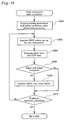
- Fig. 12 is a flowchart showing the color conversion processing in Embodiment 1.
- printing parameters are acquired first by the CPU 81, and the bronzing occurrence conditions are selected according to the printing parameters thus acquired (Step S200). Therefore, the ranges within which bronzing will occur vary according to the combination of the variety of ink and the printing paper, as discussed above.
- the variety of ink and the type of printing paper is acquired beforehand, and the definition of the conditions under which bronzing will occur is made according to this information. The acquisition of printing parameters and then the selection of bronzing occurrence parameters will be discussed below.
- Printing parameters are acquired on the basis of the settings put in to the printer driver 92 by the user of the color printer 20.
- the variety of ink is input according to the product number into the printer driver 92 as displayed on the monitor in order to specify the ink.
- the ink product number is printed on the label on the ink cartridge.
- the types of printing paper are displayed on the computer monitor. The user of the color printer 20 makes his/her selection from these. Based on this selection, the printer driver 92 specifies the printing paper. This information pertaining to the variety of ink and the type of printing paper is stored in the printer driver 92, and is stored there until the user of the color printer 20 makes other selections through the monitor display. This information is first read into the CPU 81 in Step S200.
- Fig. 3 describes the method for establishing the conditions under which bronzing occurs. This method is used to survey beforehand the conditions under which bronzing occurs for each type of ink and printing paper. If the survey results are similar to each other, there are stored as 1 summary result in Embodiment 1. In other words, since a great deal of memory capacity would be required to store all the survey results for each ink and printing paper variety, similar results are summarized as one result.
- Fig. 13(a) shows the corresponding relationship between the printing parameters (in other words, the combination of the ink varieties and paper varieties), and the stored survey results. For example, assuming that virtually the same bronzing conditions obtain when paper 1 is used with ink 1, or when paper 1 is used with ink 2, or when paper 2 is used with ink 3, these printing conditions will all be stored as Results A. As shown in Fig. 13(a), these similar survey results can be stored as a summary result for four types of survey results A through D corresponding to 9 printing parameters stored in the computer 80.
- Each survey result is stored in the formats shown in Fig. 13(b).
- the UCR rate is stored only in the range from 100% to 50%. In this way, memory usage is minimized since bronzing does not occur when the UCR rate is under 50%. Also, the black level is converted and stored according to the tone value. The reason for this is discussed below.
- the CPU 81 determines the bronzing occurrence conditions by selecting one of the above-mentioned survey results according to the printing parameter information, shown in Fig. 13(a) which has been read in. This processing is performed in Step S200.
- Fig. 14 shows a schematic diagram of a color conversion table LUT.
- the R-G-B color tone data intersect orthogonally in three axes, and the spaces formed by the three axes create a grid. If each of the R-G-B coordinates formed at the intersections of this grid is made to correspond to the R-G-B color tone data, then the intersections at each point represent a different color.
- the C-M-Y-K tone data corresponding to the intersections are stored for each and every intersection coordinate.
- the color conversion table expresses these three dimensions numerically.
- the CPU 81 performs color conversion as follows. Given, for example, that the R-G-B tone data of the image data are expressed as RA-GA-BA, then consider point A as expressed by the coordinates (RA, GA, BA) of the color conversion table. A small cube like dV which includes point A is found and the peak intersections of this cube are stored as tone data of C-M-Y-K and are read out. From these read-out tone data, These tone data which have been read out are interpolated and the tone data for C-M-Y-K corresponding to point A are computed.
- the CPU 81 computes the black level and the UCR rate upon completion of this color conversion (Step S204). While expressing the color corresponding to each intersection, the color tone data of C-M-Y-K which are stored at the intersections of the color conversion tables also set the UCR rate which enables the production of high-quality images. Thus, if for example a relatively bright color like gray is expressed, there is a tendency for K dots, which tend to stand out, to be sparsely formed, creating a poor image with a rough-looking, rather grainy appearance. Instead of K dots, the picture is enhanced through the use of composite K. On the other hand, when expressing dark colors which are close to black, the image is expressed not with composite K, but with K dots.
- ⁇ 1, ⁇ 2, and ⁇ 3 are coefficients which represent the ink proportions for the C, M, and Y colors. These coefficients are calculated experimentally beforehand.
- min ( ) is factor which selects the minimum value. For example, the smallest of X, Y, Z will be used in the case of min (X,Y, Z).
- Step S206 the CPU 81 commences processing to determine whether bronzing will take place or not based on these values. In other words, since the conditions under which bronzing will occur have already been determined in Step S200, whether or not bronzing will occur can be determined by using the black level Brk and the UCR rate values which are computed in Step S204.
- Step S206 If it is determined in Step S206 that bronzing will occur, the UCR rate will be corrected and bronzing will be avoided (Step S208). Specifically, the UCR rate is corrected as follows.
- the maximum value Rlmt of the UCR rate at which bronzing does not occur is found at the calculated black level Brk, and its difference ⁇ R between the UCR rate Rucr after color conversion is found.
- the maximum value Rlmt can be easily found by referring to these survey results.
- the color tone data for C-M-Y-K are corrected according to the following equations: Kv ⁇ Kv - ⁇ R Cv ⁇ Cv + ⁇ 1 ⁇ ⁇ R Mc ⁇ Mv + ⁇ 2 ⁇ ⁇ R Yv ⁇ Yv + ⁇ 3 ⁇ ⁇ R where the ⁇ symbol indicates subsitution.
- the symbol in A ⁇ B means that B substitutes for A.
- the values for ⁇ 1, ⁇ 2, and ⁇ 3 are found experimentally, and are the coefficients used in Formula (1), above.
- Step S210 If it is determined in the processing done in Step S206 that bronzing will not occur, a judgment is made as to whether or not color conversion processing has been completed for all picture elements (Step S210). If unprocessed picture elements are found remaining, processing is returned to Step S202 and processing is repeated. If no unprocessed picture elements are found, color conversion processing is concluded and processing is returned to the printing processing routine shown in Fig. 8.
- Embodiment 1 binary processing is performed for the corrected color tone data color conversion processing results so that bronzing does not occur. Therefore, the dots are formed at a proportion such that bronzing does not occur for the dots of each color which are judged either.
- Embodiment 1 performs color conversion processing using the existing color conversion tables, and corrects the conditions that cause bronzing to occur. Therefore, by adding data concerning new conditions which cause bronzing to occur, it is easy to obtain high-quality images without bronzing.
- the ink variety and type of printing paper used are read in as printing parameters.
- either the ink variety or the type of printing paper can be read in as printing parameters, and a judgment can be made on this basis as to whether or not bronzing will occur.
- the use of computer storage capacity can be minimized.
- Embodiment 1 the existing color conversion tables are used to perform color conversion, and color conversion results are corrected so that bronzing does not occur.
- the color conversion tables are modified bearing in mind the conditions under which bronzing occurs, and the modified color conversion tables are used to perform color conversion processing (Fig. 8, Step S104).
- Embodiment 2 is a method which uses the color conversion table which has been set up in consideration of bronzing conditions in this way.
- Embodiment 2 uses a modified color conversion table which is set up ahead of time bearing in mind the conditions under which bronzing occurs. As a result, just by executing a normal printing processing routine with the computer 80, high-quality images can be printed by the color printer 20 without the occurrence of bronzing. The conditions under which bronzing occurs are borne in mind in the following discussion about how this color conversion tables are set up.
- Fig. 15 is a flowchart describing the processing flow for setting up the color conversion table based on the conditions under which bronzing occurs.
- This processing is performed by the computer's 80 CPU 81.
- the CPU 81 corrects the existing color conversion table by performing this processing, and as a result generates a new color conversion table based on an awareness of the conditions under which bronzing occurs for each combination of inks and printing papers. Naturally, it is perfectly acceptable for color printers to be shipped from the factory with corrected color conversion tables.
- Step S300 When color conversion table correction processing is started, first printing parameters are acquired, and then the conditions under which bronzing occurs are defined (Step S300). In other words, since the conditions under which bronzing occurs vary according to the combination of ink and paper varieties, the amount of color conversion table correction will vary according to these various combinations. At this point, a decision is made about whether to correct the color conversion table in light of the anticipated printing parameters. Specifically, the operator of the computer 80 sets up the printing parameters by inputting the ink product number and the type of printing paper by using the screen display, as in Embodiment 1, discussed above.
- the conditions under which bronzing occurs are determined on the basis of the printing parameters which have been set up.
- the survey results for the conditions under which bronzing occurs are stored ahead of time for each combination of ink and paper varieties, as in Embodiment 1 (See Fig. 13).
- the corresponding survey results are defined according to the printing parameters which have been set up.
- Step S302 the C-M-Y-K color tone data which has been set up in the LUT intersections of the CPU's 81 color conversion table are read out (Step S302), and the black level and UCR rate are computed for the intersections which are read out (Step S304). Equations (1) and (2) are used for computation, as in Embodiment 1.
- Step S306 Based on the black level Brk and the UCR rate Rucr found in this way, a determination is made as to whether the tone data set up at the grid intersections is appropriate or not. In other words, a judgment is made as whether bronzing conditions are present or not (Step S306). Since the conditions under which bronzing occurs are already defined in Step S300, it is easy to use the combination of the computed black level Brk and the UCR rate Rucr to determine whether or not these are conditions under which bronzing occurs by referring to these conditions.
- the tone data for C-M-Y-K are corrected as follows (Step 308), as in Embodiment 1.
- Step S300 the conditions under which bronzing occurs which have been defined in Step S300, and the maximum value Rlmt at which bronzing does not occur for the computed black level Brk is found.
- Step S300 the maximum value Rlmt at which bronzing does not occur for the computed black level Brk is found.
- the ⁇ R value for the difference between the maximum Rlmt and the computed UCR rate Rucr is found, and the C-M-Y-K color tone data are corrected using equations 3 ⁇ 5, presented above.
- Step S306 If conditions under which bronzing occurs are identified in Step S306 processing, a determination is made as to whether tone data correction has been completed or not for all the intersections of the color conversion table (Step S310), and if unprocessed intersections are found remaining, processing is returned to Step S302 and processing is repeated. In this way, the color correction tables are corrected and stored for each combination of inks and printing papers.
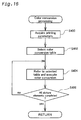
- Fig. 16 is a flowchart showing the processing flow performed in the color conversion processing in the printing processing routine (Fig. 8, Step S104), when an image is printed with a color printer 20 of Embodiment 2.
- the flowchart in Fig. 16 presents a simplified explanation of the color conversion processing done by the color printer 20.
- the CPU 81 first acquires the printing parameters (type of ink and type of printing paper) (Step S400). These parameters are input beforehand through the display screen of the CRT by the user of the color printer 20, and this information is acquired by the color printer 20.
- Step S402 the color conversion table corresponding to the acquired printing parameters is selected (Step S402). Since the color conversion tables are converted and stored for each printing parameter in the color conversion table correction processing described above, the color conversion table corresponding to the printing parameters is selected from these. In the explanation of this embodiment, it is assumed that the printer drivers will automatically select the color conversion table which is appropriate for the printing parameters. However, it is acceptable to specify externally the color conversion table appropriate for the printing parameters.
- Embodiment 2 uses corrected color conversion tables so that bronzing does not occur for any of the printing parameters. Therefore, high-quality images can ultimately be obtained without bronzing by performing processing such as binary processing for the color conversion results obtained in this way.
- the color conversion tables are corrected beforehand bearing in mind the conditions under which bronzing occurs. Printing can be done rapidly and without bronzing just by performing normal color conversion processing if these corrected color conversion tables are used for color conversion processing.
- Embodiment 2 described above, although the conditions under which bronzing occurs are considered in terms of each combination of inks and printing papers, to simplify things, either the ink variety or the type of printing paper can be considered. In so doing, processing can be done according to the color conversion table correction processing shown in Fig. 15 and the color conversion processing in Fig. 16. Also, a more economical use of memory capacity can be effected by limiting the number of color conversion tables which need to be stored, which is desirable.
Applications Claiming Priority (4)
| Application Number | Priority Date | Filing Date | Title |
|---|---|---|---|
| JP24845999 | 1999-09-02 | ||
| JP24845999 | 1999-09-02 | ||
| JP2000215583A JP3711441B2 (ja) | 1999-09-02 | 2000-07-17 | 印刷制御装置 |
| JP2000215583 | 2000-07-17 |
Publications (4)
| Publication Number | Publication Date |
|---|---|
| EP1087613A2 true EP1087613A2 (fr) | 2001-03-28 |
| EP1087613A3 EP1087613A3 (fr) | 2006-12-27 |
| EP1087613B1 EP1087613B1 (fr) | 2009-09-23 |
| EP1087613B8 EP1087613B8 (fr) | 2009-12-16 |
Family
ID=26538783
Family Applications (1)
| Application Number | Title | Priority Date | Filing Date |
|---|---|---|---|
| EP00118911A Expired - Lifetime EP1087613B8 (fr) | 1999-09-02 | 2000-08-31 | Appareil de commande d'impression et procédé de commande d'impression |
Country Status (4)
| Country | Link |
|---|---|
| US (1) | US6341833B1 (fr) |
| EP (1) | EP1087613B8 (fr) |
| JP (1) | JP3711441B2 (fr) |
| DE (1) | DE60042997D1 (fr) |
Cited By (1)
| Publication number | Priority date | Publication date | Assignee | Title |
|---|---|---|---|---|
| EP1795002A1 (fr) * | 2004-11-11 | 2007-06-13 | Ricoh Company, Ltd. | Procedes de traitement d'images, pilote d'imprimante, dispositif d'impression d'images, dispositif de traitement d'images, et systeme d'impression d'images |
Families Citing this family (15)
| Publication number | Priority date | Publication date | Assignee | Title |
|---|---|---|---|---|
| EP1257114A1 (fr) * | 2001-05-08 | 2002-11-13 | Imip Llc | Appareil de formation d'image par jet d'encre et procédé pour son fonctionnement |
| JP4562162B2 (ja) * | 2001-09-27 | 2010-10-13 | キヤノン株式会社 | 色処理方法及び装置とコンピュータプログラム、及びルックアップテーブルの製造方法 |
| US7551315B2 (en) * | 2004-02-25 | 2009-06-23 | Seiko Epson Corportion | Color matching accuracy under multiple printing conditions |
| JP4875396B2 (ja) * | 2006-04-12 | 2012-02-15 | キヤノン株式会社 | 色処理装置および方法 |
| US8194298B2 (en) * | 2006-09-28 | 2012-06-05 | Sharp Laboratories Of America, Inc. | Methods and systems for composite printer transforms |
| JP4315176B2 (ja) * | 2006-09-29 | 2009-08-19 | セイコーエプソン株式会社 | 印刷装置、印刷方法、および、印刷用プログラム |
| US20080137147A1 (en) * | 2006-12-07 | 2008-06-12 | Naoki Nakano | Image processing method, program, storage medium, image processing device, and image forming apparatus |
| JP2009269321A (ja) * | 2008-05-08 | 2009-11-19 | Ricoh Co Ltd | 画像処理方法、プログラム、記憶媒体、画像処理装置、画像形成装置 |
| JP5340051B2 (ja) * | 2009-06-19 | 2013-11-13 | キヤノン株式会社 | 画像処理方法および装置 |
| JP5748522B2 (ja) * | 2011-03-29 | 2015-07-15 | キヤノン株式会社 | インクジェット記録装置およびインクジェット記録方法 |
| JP5901200B2 (ja) * | 2011-09-29 | 2016-04-06 | キヤノン株式会社 | 画像処理装置、画像処理方法および記録物 |
| JP5988909B2 (ja) | 2012-05-08 | 2016-09-07 | キヤノン株式会社 | 画像処理装置および画像処理方法 |
| JP5988680B2 (ja) | 2012-05-08 | 2016-09-07 | キヤノン株式会社 | 画像処理装置およびインクジェット記録方法 |
| JP5988679B2 (ja) * | 2012-05-08 | 2016-09-07 | キヤノン株式会社 | 画像処理装置、インクジェット記録装置および画像処理方法 |
| JP5955088B2 (ja) * | 2012-05-08 | 2016-07-20 | キヤノン株式会社 | 画像処理装置および画像処理方法 |
Citations (2)
| Publication number | Priority date | Publication date | Assignee | Title |
|---|---|---|---|---|
| JPH07214892A (ja) | 1994-02-04 | 1995-08-15 | Mitsubishi Paper Mills Ltd | 転写用シート |
| JPH10217603A (ja) | 1997-02-12 | 1998-08-18 | Canon Inc | 記録媒体、その製造方法、これを用いた画像形成方法及び分散液 |
Family Cites Families (6)
| Publication number | Priority date | Publication date | Assignee | Title |
|---|---|---|---|---|
| JP2784572B2 (ja) | 1988-02-15 | 1998-08-06 | キヤノン株式会社 | カラー画像処理方法 |
| US5402245A (en) * | 1994-01-27 | 1995-03-28 | Hewlett-Packard Company | Bi-level digital color printer system exhibiting improved undercolor removal and error diffusion procedures |
| JPH0969960A (ja) * | 1995-09-01 | 1997-03-11 | Brother Ind Ltd | 印刷出力装置 |
| US5905490A (en) * | 1996-02-26 | 1999-05-18 | Seiko Epson Corporation | Generating color-correction look-up-table addresses by multi-level half-toning |
| JPH115359A (ja) | 1997-06-18 | 1999-01-12 | Konica Corp | インクジェット記録用シート |
| US5966462A (en) * | 1997-06-19 | 1999-10-12 | Xerox Corporation | Method and system for processing and rendering object oriented neutral image data |
-
2000
- 2000-07-17 JP JP2000215583A patent/JP3711441B2/ja not_active Expired - Fee Related
- 2000-08-31 EP EP00118911A patent/EP1087613B8/fr not_active Expired - Lifetime
- 2000-08-31 DE DE60042997T patent/DE60042997D1/de not_active Expired - Lifetime
- 2000-09-01 US US09/654,707 patent/US6341833B1/en not_active Expired - Fee Related
Patent Citations (2)
| Publication number | Priority date | Publication date | Assignee | Title |
|---|---|---|---|---|
| JPH07214892A (ja) | 1994-02-04 | 1995-08-15 | Mitsubishi Paper Mills Ltd | 転写用シート |
| JPH10217603A (ja) | 1997-02-12 | 1998-08-18 | Canon Inc | 記録媒体、その製造方法、これを用いた画像形成方法及び分散液 |
Cited By (2)
| Publication number | Priority date | Publication date | Assignee | Title |
|---|---|---|---|---|
| EP1795002A1 (fr) * | 2004-11-11 | 2007-06-13 | Ricoh Company, Ltd. | Procedes de traitement d'images, pilote d'imprimante, dispositif d'impression d'images, dispositif de traitement d'images, et systeme d'impression d'images |
| EP1795002A4 (fr) * | 2004-11-11 | 2008-12-24 | Ricoh Kk | Procedes de traitement d'images, pilote d'imprimante, dispositif d'impression d'images, dispositif de traitement d'images, et systeme d'impression d'images |
Also Published As
| Publication number | Publication date |
|---|---|
| US6341833B1 (en) | 2002-01-29 |
| EP1087613B8 (fr) | 2009-12-16 |
| JP2001138555A (ja) | 2001-05-22 |
| JP3711441B2 (ja) | 2005-11-02 |
| DE60042997D1 (de) | 2009-11-05 |
| EP1087613A3 (fr) | 2006-12-27 |
| EP1087613B1 (fr) | 2009-09-23 |
Similar Documents
| Publication | Publication Date | Title |
|---|---|---|
| US7883168B2 (en) | Reduction of dependence of color appearance on light source | |
| US6351320B1 (en) | Memory-saving printer driver | |
| US7562956B2 (en) | Image printing using print quality enhancing ink | |
| EP1087613B1 (fr) | Appareil de commande d'impression et procédé de commande d'impression | |
| JP4348748B2 (ja) | 印刷装置および画像記録方法 | |
| US7936481B2 (en) | Method, system and program for forming an image | |
| JP4675296B2 (ja) | 印刷装置および印刷方法 | |
| US20080036812A1 (en) | Image processing device and printing apparatus for performing bidirectional printing | |
| US20080024826A1 (en) | Image processing device and printing apparatus for performing bidirectional printing | |
| US20090147283A1 (en) | Ejecion control of quality-enhancing ink | |
| JP5165130B6 (ja) | 画像処理装置および画像処理方法 | |
| JP4003046B2 (ja) | 印刷制御装置、印刷制御方法、印刷システム、印刷制御プログラムおよび印刷制御プログラムを記録した媒体 | |
| US6302521B1 (en) | Method and apparatus for expanded color space in acoustic ink printing | |
| US8130416B2 (en) | Image forming apparatus, image forming method, computer program, and recording medium | |
| US7367156B2 (en) | Inkjet recording device and inkjet recording method | |
| US20090135439A1 (en) | Method And Apparatus For Printing A High Resolution Image With A Printhead In A Multi-Pass Printing Mode | |
| US7362473B2 (en) | Image processing technique for tone number conversion of image data | |
| JP4525818B2 (ja) | 印刷装置および画像記録方法 | |
| JP2001353888A (ja) | 印刷制御装置、画像処理装置 | |
| JP2003276249A (ja) | 画像データの階調数を変換する画像処理装置 | |
| JP4687591B2 (ja) | 印刷装置、印刷プログラム、印刷方法および画像処理装置、画像処理プログラム、ならびに画像処理方法 |
Legal Events
| Date | Code | Title | Description |
|---|---|---|---|
| PUAI | Public reference made under article 153(3) epc to a published international application that has entered the european phase |
Free format text: ORIGINAL CODE: 0009012 |
|
| AK | Designated contracting states |
Kind code of ref document: A2 Designated state(s): AT BE CH CY DE DK ES FI FR GB GR IE IT LI LU MC NL PT SE |
|
| AX | Request for extension of the european patent |
Free format text: AL;LT;LV;MK;RO;SI |
|
| PUAL | Search report despatched |
Free format text: ORIGINAL CODE: 0009013 |
|
| AK | Designated contracting states |
Kind code of ref document: A3 Designated state(s): AT BE CH CY DE DK ES FI FR GB GR IE IT LI LU MC NL PT SE |
|
| AX | Request for extension of the european patent |
Extension state: AL LT LV MK RO SI |
|
| 17P | Request for examination filed |
Effective date: 20070124 |
|
| 17Q | First examination report despatched |
Effective date: 20070216 |
|
| AKX | Designation fees paid |
Designated state(s): DE FR GB |
|
| RTI1 | Title (correction) |
Free format text: PRINT CONTROL APPARATUS AND PRINT CONTROL METHOD |
|
| GRAP | Despatch of communication of intention to grant a patent |
Free format text: ORIGINAL CODE: EPIDOSNIGR1 |
|
| GRAS | Grant fee paid |
Free format text: ORIGINAL CODE: EPIDOSNIGR3 |
|
| GRAA | (expected) grant |
Free format text: ORIGINAL CODE: 0009210 |
|
| AK | Designated contracting states |
Kind code of ref document: B1 Designated state(s): DE FR GB |
|
| REG | Reference to a national code |
Ref country code: GB Ref legal event code: FG4D |
|
| REF | Corresponds to: |
Ref document number: 60042997 Country of ref document: DE Date of ref document: 20091105 Kind code of ref document: P |
|
| RIN2 | Information on inventor provided after grant (corrected) |
Inventor name: YAMAMOTO, YUKO,C/O SEIKO EPSON CORPORATION Inventor name: LIU SA,C/O SEIKO EPSON CORPORATION |
|
| PLBE | No opposition filed within time limit |
Free format text: ORIGINAL CODE: 0009261 |
|
| STAA | Information on the status of an ep patent application or granted ep patent |
Free format text: STATUS: NO OPPOSITION FILED WITHIN TIME LIMIT |
|
| 26N | No opposition filed |
Effective date: 20100624 |
|
| GBPC | Gb: european patent ceased through non-payment of renewal fee |
Effective date: 20100831 |
|
| REG | Reference to a national code |
Ref country code: FR Ref legal event code: ST Effective date: 20110502 |
|
| PG25 | Lapsed in a contracting state [announced via postgrant information from national office to epo] |
Ref country code: FR Free format text: LAPSE BECAUSE OF NON-PAYMENT OF DUE FEES Effective date: 20100831 |
|
| PG25 | Lapsed in a contracting state [announced via postgrant information from national office to epo] |
Ref country code: GB Free format text: LAPSE BECAUSE OF NON-PAYMENT OF DUE FEES Effective date: 20100831 |
|
| PGFP | Annual fee paid to national office [announced via postgrant information from national office to epo] |
Ref country code: DE Payment date: 20110824 Year of fee payment: 12 |
|
| PG25 | Lapsed in a contracting state [announced via postgrant information from national office to epo] |
Ref country code: DE Free format text: LAPSE BECAUSE OF NON-PAYMENT OF DUE FEES Effective date: 20130301 |
|
| REG | Reference to a national code |
Ref country code: DE Ref legal event code: R119 Ref document number: 60042997 Country of ref document: DE Effective date: 20130301 |