EP1087208A2 - Méthode pour la navigation d'un véhicule - Google Patents
Méthode pour la navigation d'un véhicule Download PDFInfo
- Publication number
- EP1087208A2 EP1087208A2 EP00118041A EP00118041A EP1087208A2 EP 1087208 A2 EP1087208 A2 EP 1087208A2 EP 00118041 A EP00118041 A EP 00118041A EP 00118041 A EP00118041 A EP 00118041A EP 1087208 A2 EP1087208 A2 EP 1087208A2
- Authority
- EP
- European Patent Office
- Prior art keywords
- vehicle
- determined
- difference
- time
- absolute
- Prior art date
- Legal status (The legal status is an assumption and is not a legal conclusion. Google has not performed a legal analysis and makes no representation as to the accuracy of the status listed.)
- Granted
Links
- 238000000034 method Methods 0.000 title claims abstract description 17
- 230000010354 integration Effects 0.000 claims abstract description 11
- 238000012937 correction Methods 0.000 claims description 12
- 238000012545 processing Methods 0.000 description 11
- 230000035945 sensitivity Effects 0.000 description 8
- YBJHBAHKTGYVGT-ZKWXMUAHSA-N (+)-Biotin Chemical compound N1C(=O)N[C@@H]2[C@H](CCCCC(=O)O)SC[C@@H]21 YBJHBAHKTGYVGT-ZKWXMUAHSA-N 0.000 description 4
- FEPMHVLSLDOMQC-UHFFFAOYSA-N virginiamycin-S1 Natural products CC1OC(=O)C(C=2C=CC=CC=2)NC(=O)C2CC(=O)CCN2C(=O)C(CC=2C=CC=CC=2)N(C)C(=O)C2CCCN2C(=O)C(CC)NC(=O)C1NC(=O)C1=NC=CC=C1O FEPMHVLSLDOMQC-UHFFFAOYSA-N 0.000 description 4
- 238000011156 evaluation Methods 0.000 description 2
- 238000009434 installation Methods 0.000 description 2
- 238000013459 approach Methods 0.000 description 1
- 230000005540 biological transmission Effects 0.000 description 1
- 230000015572 biosynthetic process Effects 0.000 description 1
- 230000008878 coupling Effects 0.000 description 1
- 238000010168 coupling process Methods 0.000 description 1
- 238000005859 coupling reaction Methods 0.000 description 1
- 230000001419 dependent effect Effects 0.000 description 1
- 230000000694 effects Effects 0.000 description 1
- 238000001914 filtration Methods 0.000 description 1
- VKYKSIONXSXAKP-UHFFFAOYSA-N hexamethylenetetramine Chemical compound C1N(C2)CN3CN1CN2C3 VKYKSIONXSXAKP-UHFFFAOYSA-N 0.000 description 1
- 230000007935 neutral effect Effects 0.000 description 1
- 230000009897 systematic effect Effects 0.000 description 1
Images
Classifications
-
- G—PHYSICS
- G01—MEASURING; TESTING
- G01C—MEASURING DISTANCES, LEVELS OR BEARINGS; SURVEYING; NAVIGATION; GYROSCOPIC INSTRUMENTS; PHOTOGRAMMETRY OR VIDEOGRAMMETRY
- G01C21/00—Navigation; Navigational instruments not provided for in groups G01C1/00 - G01C19/00
- G01C21/26—Navigation; Navigational instruments not provided for in groups G01C1/00 - G01C19/00 specially adapted for navigation in a road network
- G01C21/28—Navigation; Navigational instruments not provided for in groups G01C1/00 - G01C19/00 specially adapted for navigation in a road network with correlation of data from several navigational instruments
Definitions
- the invention relates to a method for navigating a Vehicle in which a change of direction of the vehicle by integrating a direction change speed indicating signal is determined.
- Such a method is used, for example, for a "Carin" navigation system used.
- the need for navigation aids has increased in recent years continuously increased.
- the overall task is structured here in three parts, namely the position determination of the vehicle, the route planning and the transmission the route to the driver.
- the present Invention relates to the first section, namely the Positioning of the vehicle.
- Gyroscopes For the determination of the direction in the known case Gyroscopes used. Gyroscopes generate an output signal, for when driving straight ahead or at a standstill (no change of direction) naturalized the term "drift" Has. When the vehicle changes direction changes the output signal, that of the angular velocity ⁇ of the vehicle depends. By integrating this signal over time you can then determine the change in direction.
- a gyroscope can have an output voltage range from 0 to 5 V, in the neutral position, i.e. when the vehicle is driving straight or an output voltage (drift) of 2.5 V is output becomes.
- the change in output signal related to the angular velocity, i.e. mV / (° / s), is called sensitivity (sensitivity).
- the invention has for its object directions to be able to determine more precisely.
- Steps a-c do not have to be done with every change of direction be performed.
- Under external Aids should be understood to mean those that do not Influence on the gyroscope or on a comparable one Have unity and are not affected by the gyroscope become.
- the difference between the two absolute Directions can be determined relatively precisely. If the Sensitivity is right, the result of the integration should correspond to this difference in direction. If that is not the case, you can use a correction quantity for example form by using the previously used Correction quantity multiplied by the quotient from the difference of the absolute directions and the integration result.
- Such a calibration can be made while driving because the vehicle undergoes a change of direction here often. In order to influencing factors can also be taken into account change the sensitivity while driving.
- the Calibration can be done with relatively few additional ones Perform steps, reducing the processing overhead remains small for the navigation system. Additionally receives one has the advantage that this calibration also the influence of the installation position of the gyroscope on its output signal can be taken
- Preferably external satellites are used used. Positioning with the help of satellites is relatively inaccurate, as stated above.
- the Direction determination with the help of satellites is however much more accurate.
- the signal from the navigation satellites is evaluated usually every second off, i.e. with a frequency of 1 Hz. So you can assume that in this short period of time systematic positioning errors not significant has changed, so that when making a difference between two positions eliminates the error.
- the streets are preferably stored in a database. This facilitates the evaluation with the help of a Computers, which anyway for the evaluation of the other data required for navigation is required.
- the correction variable is advantageously only determined if if the difference in absolute directions is at least Is 60 °. In this case, the result of the integration large enough so that here, for example, a discretization error no longer plays a major role. Changes in direction with a difference of at least 60 ° occur, for example, when the vehicle turns at right angles. Larger changes in direction result For example, when the vehicle is on a Highway intersection wants to turn left. Because a crossing the oncoming lane is excluded the vehicle usually changes direction here Execute by 270 °.
- the correction variable is preferably only determined when if in the period between the first time and the second time a predetermined average Angular velocity is not fallen below. For example, the calibration is suspended if the mean angular velocity is less than 1 ° / sec. is. In this case you reduce the risk that Drift deviations negatively affect the determination of the correction quantity impact.
- the correction variable is preferably filtered.
- the Influence of a current correction quantity determination then always put in a larger context, like this that, for example, "outliers" are not too negative impact. With such a filtering one can also ensure that correction values that follow a large Change of direction can be determined, a larger one Get weight as corrective measures after a small change in direction can be determined.
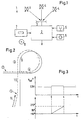
- a system 1 for navigating a vehicle is only included shown a section that deals with the position determination deals.
- a processing device 2 is connected to an antenna 3, the signals from navigation satellites 4 receives. With the help of satellites the positions and directions are spaced from one second, i.e. determined with a frequency of 1 Hz. You can see the distance over the duration of signals to calculate the satellite 4. If the distance is known to at least three satellites, then you can calculate the position of the vehicle on earth. However, this position is with certain Buggy.
- the processing device 2 is also connected to a schematically represented gyroscope 5, the Output signal shown in Fig. 3 (upper graph) is. Finally there is a tachometer 6 with the processing device connected to that of the processing device 2 reports the distance traveled.
- the processing device 2 is also with a schematically illustrated database 7 connected also formed by a reader for a data carrier 8 can be, for example, a CD-ROM. On the database 7 streets can be filed so that they from the processing device 2, for example one Computers that can be recycled.
- the processing facility 2 can be the current position, for example of the vehicle on the road on which the Vehicle is currently located. This procedure will also known as "map matching".
- database 7 is used for route planning, but in this case is of minor interest.
- the system uses for location or position determination of the vehicle to a significant extent so-called “dead reckoning” referred to as. From a known location the distance from the vehicle in which direction travels. The distance is with Using the tachometer 6 determines the direction with Help of the gyroscope 5. By vectorial addition of the individual directed routes can be the current Determine the position of the vehicle.
- the gyroscope 5 then gives when the vehicle is straight drives, a constant voltage of 2.5 V, for example from.
- This constant output voltage of the gyroscope 5 is also called “drift”.
- sensitivity normalizes the deviation of the output signal to an angular velocity. If you integrate this deviation over time, how this is shown in Fig. 3 below, then you get an indication of the angle traveled.
- FIG. 2 shows an example of the course of a street 9. Such a course of the road results, for example at a motorway junction where there is a northbound Want to turn the vehicle west. It will assume that the vehicle is on street 9.
- a course 10 is drawn in with dashed lines Processing device 2 calculated by coupling navigation Has. Due to some inaccuracies and errors, that resulted from this calculation, the course 10 does not exactly match the street 9. In particular, one can see in a section 11 that the direction of the course 10 is not with the direction of street 9 coincides.
- the 270 ° rotation begins at time 3 ⁇ and ends at time 4 ⁇ .
- the Output voltage increases from 2.5 V to 2.6 V.
- the integrated output signal is plotted underneath which should display 270 ° accordingly.
- ⁇ which is, for example, 1,000 °.
- ⁇ which is, for example, 1,000 °.
- the driven Curve include an angle of 60 ° or more. Between the first time 1 ⁇ and the second time 2 ⁇ The mean angular velocity must not be less than a predetermined value. If this Value for example 1 ° / sec. the entire change of direction be at least 60 ° if the time difference 60 sec is.
Landscapes
- Engineering & Computer Science (AREA)
- Radar, Positioning & Navigation (AREA)
- Remote Sensing (AREA)
- Automation & Control Theory (AREA)
- Physics & Mathematics (AREA)
- General Physics & Mathematics (AREA)
- Navigation (AREA)
Applications Claiming Priority (2)
| Application Number | Priority Date | Filing Date | Title |
|---|---|---|---|
| DE19945120A DE19945120C2 (de) | 1999-09-21 | 1999-09-21 | Verfahren zum Navigieren eines Fahrzeugs |
| DE19945120 | 1999-09-21 |
Publications (3)
| Publication Number | Publication Date |
|---|---|
| EP1087208A2 true EP1087208A2 (fr) | 2001-03-28 |
| EP1087208A3 EP1087208A3 (fr) | 2004-01-21 |
| EP1087208B1 EP1087208B1 (fr) | 2007-02-28 |
Family
ID=7922709
Family Applications (1)
| Application Number | Title | Priority Date | Filing Date |
|---|---|---|---|
| EP00118041A Expired - Lifetime EP1087208B1 (fr) | 1999-09-21 | 2000-08-23 | Méthode pour la navigation d'un véhicule |
Country Status (3)
| Country | Link |
|---|---|
| US (1) | US6366850B1 (fr) |
| EP (1) | EP1087208B1 (fr) |
| DE (2) | DE19945120C2 (fr) |
Citations (8)
| Publication number | Priority date | Publication date | Assignee | Title |
|---|---|---|---|---|
| JPS59104510A (ja) * | 1982-12-06 | 1984-06-16 | Mitsubishi Electric Corp | 車載用方位センサ− |
| US4743913A (en) * | 1986-02-19 | 1988-05-10 | Nissan Motor Company, Limited | Hybrid navigation system for determining a relative position and direction of a vehicle and method therefor |
| GB2216272A (en) * | 1988-02-29 | 1989-10-04 | Nissan Motor | Vehicle's driving azimuth detecting apparatus correcting disturbed geomagnetic azimuth |
| JPH01295312A (ja) * | 1988-05-24 | 1989-11-29 | Toshiba Corp | 無人車誘導装置 |
| EP0373317A2 (fr) * | 1988-10-14 | 1990-06-20 | Sumitomo Electric Industries, Ltd. | Dispositif et méthode pour déterminer des erreurs dans les données d'un capteur magnétique de direction |
| EP0496517A1 (fr) * | 1991-01-23 | 1992-07-29 | Sumitomo Electric Industries, Ltd. | Méthode pour calculer le facteur d'échelle d'un gyroscope |
| DE4208158A1 (de) * | 1991-03-13 | 1992-09-17 | Tokimec Inc | Kreiselsystem |
| EP0844462A2 (fr) * | 1996-11-22 | 1998-05-27 | Zexel Corporation | Méthode et dispositif pour déterminer la position d'un objet en mouvement |
Family Cites Families (7)
| Publication number | Priority date | Publication date | Assignee | Title |
|---|---|---|---|---|
| JP2946051B2 (ja) * | 1990-02-22 | 1999-09-06 | 株式会社トキメック | ジャイロ装置 |
| JP2946050B2 (ja) * | 1990-02-22 | 1999-09-06 | 株式会社トキメック | ジャイロ装置 |
| US5345382A (en) * | 1992-05-15 | 1994-09-06 | Zexel Corporation | Calibration method for a relative heading sensor |
| US5572217A (en) * | 1993-06-04 | 1996-11-05 | Flawn; Brian J. | Compass |
| US5928309A (en) * | 1996-02-05 | 1999-07-27 | Korver; Kelvin | Navigation/guidance system for a land-based vehicle |
| KR100296666B1 (ko) * | 1996-05-31 | 2001-08-07 | 하기와라 가즈토시 | 내비게이션장치 |
| US5877723A (en) * | 1997-03-05 | 1999-03-02 | Caterpillar Inc. | System and method for determining an operating point |
-
1999
- 1999-09-21 DE DE19945120A patent/DE19945120C2/de not_active Expired - Fee Related
-
2000
- 2000-08-23 EP EP00118041A patent/EP1087208B1/fr not_active Expired - Lifetime
- 2000-08-23 DE DE50014109T patent/DE50014109D1/de not_active Expired - Fee Related
- 2000-09-07 US US09/657,077 patent/US6366850B1/en not_active Expired - Fee Related
Patent Citations (8)
| Publication number | Priority date | Publication date | Assignee | Title |
|---|---|---|---|---|
| JPS59104510A (ja) * | 1982-12-06 | 1984-06-16 | Mitsubishi Electric Corp | 車載用方位センサ− |
| US4743913A (en) * | 1986-02-19 | 1988-05-10 | Nissan Motor Company, Limited | Hybrid navigation system for determining a relative position and direction of a vehicle and method therefor |
| GB2216272A (en) * | 1988-02-29 | 1989-10-04 | Nissan Motor | Vehicle's driving azimuth detecting apparatus correcting disturbed geomagnetic azimuth |
| JPH01295312A (ja) * | 1988-05-24 | 1989-11-29 | Toshiba Corp | 無人車誘導装置 |
| EP0373317A2 (fr) * | 1988-10-14 | 1990-06-20 | Sumitomo Electric Industries, Ltd. | Dispositif et méthode pour déterminer des erreurs dans les données d'un capteur magnétique de direction |
| EP0496517A1 (fr) * | 1991-01-23 | 1992-07-29 | Sumitomo Electric Industries, Ltd. | Méthode pour calculer le facteur d'échelle d'un gyroscope |
| DE4208158A1 (de) * | 1991-03-13 | 1992-09-17 | Tokimec Inc | Kreiselsystem |
| EP0844462A2 (fr) * | 1996-11-22 | 1998-05-27 | Zexel Corporation | Méthode et dispositif pour déterminer la position d'un objet en mouvement |
Non-Patent Citations (1)
| Title |
|---|
| PATENT ABSTRACTS OF JAPAN vol. 008, no. 219 (P-306), 5. Oktober 1984 (1984-10-05) & JP 59 104510 A (MITSUBISHI DENKI KK), 16. Juni 1984 (1984-06-16) * |
Also Published As
| Publication number | Publication date |
|---|---|
| US6366850B1 (en) | 2002-04-02 |
| DE50014109D1 (de) | 2007-04-12 |
| EP1087208B1 (fr) | 2007-02-28 |
| DE19945120C2 (de) | 2001-12-06 |
| DE19945120A1 (de) | 2001-04-12 |
| EP1087208A3 (fr) | 2004-01-21 |
Similar Documents
| Publication | Publication Date | Title |
|---|---|---|
| DE69728501T2 (de) | Fahrzeugnavigationssystem | |
| DE69826340T2 (de) | Verfahren und Gerät zur Bestimmung eines alternativen Leitweges in einem Fahrzeugsnavigationssystem | |
| DE69219006T2 (de) | Fahrzeugpositionsbestimmungsvorrichtung | |
| DE19735946A1 (de) | Fahrzeugnavigationssystem zum Einstellen von Richtungsbezeichnungen von Verbindungsstraßen und Verfahren zum Durchführen des Gleichen | |
| DE60027879T2 (de) | ROUTENFüHRUNGSVORRICHTUNG | |
| DE112005003090T5 (de) | Navigationsvorrichtung | |
| DE10050765A1 (de) | Streckenfestlegungsvorrichtung und Navigationsvorrichtung | |
| DE10022528A1 (de) | Fahrzeugnavigationssystem mit einer Fahrbahnkurveninformationsfunktion | |
| DE102016213817B4 (de) | Verfahren, Vorrichtung und computerlesbares Speichermedium mit Instruktionen zur Bestimmung der lateralen Position eines Fahrzeuges relativ zu den Fahrstreifen einer Fahrbahn | |
| DE102009001553A1 (de) | Fahrassistenzsystem, Fahrassistenzverfahren und Computerprogramm | |
| DE10307591A1 (de) | Navigationsvorrichtung und Navigationsverfahren | |
| EP0730726A1 (fr) | Procede de realisation d'une carte routiere numerisee | |
| DE102006027832A1 (de) | Fahrzeugnavigationssystem | |
| DE19519066A1 (de) | Verfahren und System zur Zielführung eines Fahrzeugs | |
| WO2000077474A1 (fr) | Appareil de navigation | |
| DE102009022881A1 (de) | Verfahren und Navigationseinrichtung zur geographischen Positionsbestimmung | |
| EP1380021B1 (fr) | Procede pour actionner un systeme de navigation pour vehicule | |
| DE10319445A1 (de) | Fahrerassistenzvorrichtung mit Kursprädiktionsmodul | |
| EP1301755B1 (fr) | Systeme de navigation et procede de correction de position | |
| DE102020105313A1 (de) | Verfahren, Recheneinrichtung und System zum Kartographieren von Landmarken eines Straßennetzes in einer Straßenkarte | |
| DE3938174C2 (de) | Vorrichtung zur Feststellung, ob die von einem Fahrzeug befahrene Straße eine Hochstraße ist | |
| DE19945121C2 (de) | Verfahren zum Navigieren eines Fahrzeugs | |
| DE19753172A1 (de) | Verfahren zur rechnergestützten Navigation eines Fahrzeuges mit einem Endgerät, Endgerät und Verkehrszentrale | |
| EP0928410A1 (fr) | Procede et systeme d'aide a la navigation pour un conducteur de vehicule | |
| DE102009042470A1 (de) | Anordnung und Verfahren zur Erfassung von Gebühren auf mautpflichtigen Straßen |
Legal Events
| Date | Code | Title | Description |
|---|---|---|---|
| PUAI | Public reference made under article 153(3) epc to a published international application that has entered the european phase |
Free format text: ORIGINAL CODE: 0009012 |
|
| AK | Designated contracting states |
Kind code of ref document: A2 Designated state(s): AT BE CH CY DE DK ES FI FR GB GR IE IT LI LU MC NL PT SE |
|
| AX | Request for extension of the european patent |
Free format text: AL;LT;LV;MK;RO;SI |
|
| RAP1 | Party data changed (applicant data changed or rights of an application transferred) |
Owner name: SIEMENS AKTIENGESELLSCHAFT |
|
| PUAL | Search report despatched |
Free format text: ORIGINAL CODE: 0009013 |
|
| AK | Designated contracting states |
Kind code of ref document: A3 Designated state(s): AT BE CH CY DE DK ES FI FR GB GR IE IT LI LU MC NL PT SE |
|
| AX | Request for extension of the european patent |
Extension state: AL LT LV MK RO SI |
|
| RIC1 | Information provided on ipc code assigned before grant |
Ipc: 7G 01C 21/16 B Ipc: 7G 01S 5/14 B Ipc: 7G 01C 17/38 B Ipc: 7G 01C 21/28 A |
|
| 17P | Request for examination filed |
Effective date: 20040216 |
|
| AKX | Designation fees paid |
Designated state(s): DE FR GB |
|
| 17Q | First examination report despatched |
Effective date: 20060630 |
|
| GRAP | Despatch of communication of intention to grant a patent |
Free format text: ORIGINAL CODE: EPIDOSNIGR1 |
|
| GRAS | Grant fee paid |
Free format text: ORIGINAL CODE: EPIDOSNIGR3 |
|
| GRAA | (expected) grant |
Free format text: ORIGINAL CODE: 0009210 |
|
| AK | Designated contracting states |
Kind code of ref document: B1 Designated state(s): DE FR GB |
|
| REG | Reference to a national code |
Ref country code: GB Ref legal event code: FG4D Free format text: NOT ENGLISH |
|
| REF | Corresponds to: |
Ref document number: 50014109 Country of ref document: DE Date of ref document: 20070412 Kind code of ref document: P |
|
| GBT | Gb: translation of ep patent filed (gb section 77(6)(a)/1977) |
Effective date: 20070523 |
|
| ET | Fr: translation filed | ||
| PLBE | No opposition filed within time limit |
Free format text: ORIGINAL CODE: 0009261 |
|
| STAA | Information on the status of an ep patent application or granted ep patent |
Free format text: STATUS: NO OPPOSITION FILED WITHIN TIME LIMIT |
|
| 26N | No opposition filed |
Effective date: 20071129 |
|
| PGFP | Annual fee paid to national office [announced via postgrant information from national office to epo] |
Ref country code: DE Payment date: 20080822 Year of fee payment: 9 |
|
| PGFP | Annual fee paid to national office [announced via postgrant information from national office to epo] |
Ref country code: FR Payment date: 20080813 Year of fee payment: 9 |
|
| PGFP | Annual fee paid to national office [announced via postgrant information from national office to epo] |
Ref country code: GB Payment date: 20080821 Year of fee payment: 9 |
|
| GBPC | Gb: european patent ceased through non-payment of renewal fee |
Effective date: 20090823 |
|
| REG | Reference to a national code |
Ref country code: FR Ref legal event code: ST Effective date: 20100430 |
|
| PG25 | Lapsed in a contracting state [announced via postgrant information from national office to epo] |
Ref country code: DE Free format text: LAPSE BECAUSE OF NON-PAYMENT OF DUE FEES Effective date: 20100302 Ref country code: FR Free format text: LAPSE BECAUSE OF NON-PAYMENT OF DUE FEES Effective date: 20090831 |
|
| PG25 | Lapsed in a contracting state [announced via postgrant information from national office to epo] |
Ref country code: GB Free format text: LAPSE BECAUSE OF NON-PAYMENT OF DUE FEES Effective date: 20090823 |