EP1087032A1 - Sputtering target and its manufacturing method - Google Patents
Sputtering target and its manufacturing method Download PDFInfo
- Publication number
- EP1087032A1 EP1087032A1 EP00120582A EP00120582A EP1087032A1 EP 1087032 A1 EP1087032 A1 EP 1087032A1 EP 00120582 A EP00120582 A EP 00120582A EP 00120582 A EP00120582 A EP 00120582A EP 1087032 A1 EP1087032 A1 EP 1087032A1
- Authority
- EP
- European Patent Office
- Prior art keywords
- alloy powder
- rare earth
- target
- sputtering
- magnetic permeability
- Prior art date
- Legal status (The legal status is an assumption and is not a legal conclusion. Google has not performed a legal analysis and makes no representation as to the accuracy of the status listed.)
- Withdrawn
Links
Images

Classifications
-
- C—CHEMISTRY; METALLURGY
- C23—COATING METALLIC MATERIAL; COATING MATERIAL WITH METALLIC MATERIAL; CHEMICAL SURFACE TREATMENT; DIFFUSION TREATMENT OF METALLIC MATERIAL; COATING BY VACUUM EVAPORATION, BY SPUTTERING, BY ION IMPLANTATION OR BY CHEMICAL VAPOUR DEPOSITION, IN GENERAL; INHIBITING CORROSION OF METALLIC MATERIAL OR INCRUSTATION IN GENERAL
- C23C—COATING METALLIC MATERIAL; COATING MATERIAL WITH METALLIC MATERIAL; SURFACE TREATMENT OF METALLIC MATERIAL BY DIFFUSION INTO THE SURFACE, BY CHEMICAL CONVERSION OR SUBSTITUTION; COATING BY VACUUM EVAPORATION, BY SPUTTERING, BY ION IMPLANTATION OR BY CHEMICAL VAPOUR DEPOSITION, IN GENERAL
- C23C14/00—Coating by vacuum evaporation, by sputtering or by ion implantation of the coating forming material
- C23C14/22—Coating by vacuum evaporation, by sputtering or by ion implantation of the coating forming material characterised by the process of coating
- C23C14/34—Sputtering
- C23C14/3407—Cathode assembly for sputtering apparatus, e.g. Target
- C23C14/3414—Metallurgical or chemical aspects of target preparation, e.g. casting, powder metallurgy
-
- C—CHEMISTRY; METALLURGY
- C23—COATING METALLIC MATERIAL; COATING MATERIAL WITH METALLIC MATERIAL; CHEMICAL SURFACE TREATMENT; DIFFUSION TREATMENT OF METALLIC MATERIAL; COATING BY VACUUM EVAPORATION, BY SPUTTERING, BY ION IMPLANTATION OR BY CHEMICAL VAPOUR DEPOSITION, IN GENERAL; INHIBITING CORROSION OF METALLIC MATERIAL OR INCRUSTATION IN GENERAL
- C23C—COATING METALLIC MATERIAL; COATING MATERIAL WITH METALLIC MATERIAL; SURFACE TREATMENT OF METALLIC MATERIAL BY DIFFUSION INTO THE SURFACE, BY CHEMICAL CONVERSION OR SUBSTITUTION; COATING BY VACUUM EVAPORATION, BY SPUTTERING, BY ION IMPLANTATION OR BY CHEMICAL VAPOUR DEPOSITION, IN GENERAL
- C23C14/00—Coating by vacuum evaporation, by sputtering or by ion implantation of the coating forming material
- C23C14/22—Coating by vacuum evaporation, by sputtering or by ion implantation of the coating forming material characterised by the process of coating
- C23C14/34—Sputtering
Definitions
- This invention relates to a sputtering target and its manufacturing method especially suitable for application to an alloy target used for sputtering in a manufacturing process of a magneto-optical recording medium.
- magnetron sputtering for manufacturing a medium, magnetron sputtering, among others, is used for stacking its recording material.
- a target containing the recording material is used for deposition of the recording medium by magnetron sputtering.
- Such a target includes as its major component a rare earth element which is a rare element and expensive.
- targets conventionally used for manufacturing mediums had magnetic permeability around 5. Therefore, the maximum thickness of a target enabling stable discharge of plasma and sputtering was about 8 mm.
- Literature 1 teaches a method for manufacturing a magneto-optical recording alloy target made by hot-pressing alloy powder made by mechanical crushing and having a magnetic permeability not exceeding 3, and a method for manufacturing a magneto-optical recording alloy target made by mechanically crushing used targets into alloy powder and mixing it with new alloy powder and having a magnetic permeability not exceeding 3.
- Literature 1 also teaches that a target having a low magnetic permeability, low containment of oxygen, single-sintered structure of a rare earth metal and a transition metal, and a thickness not less than 8 mm can be made by dissolving a source material and used targets, then making a quickly cooled alloy, and mechanically crushing the quickly cooled alloy into alloy powder.
- the alloy powder described in Literature 1 is made through a mechanical crushing process. Since rare earth alloys are very hard, a crushing member of their crushing machine is liable to abrade. Therefore, alloy powder made by mechanical crushing results in containing a large amount of metal impurities, and a target made by using the alloy powder inevitably contains a large amount of metal impurities.
- Literature 1 does not teach a magneto-optical recording alloy target having a magnetic permeability not larger than 2.3, according to the Inventor's knowledge, a 10 mm thick target having a magnetic permeability around 2.3 as taught by Literature 1 cannot be sputtered.
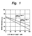
- the Inventor first made reviews about theoretic density ratios of targets fabricated. According to the Inventor's knowledge, rare earth alloy powder is very readily oxidized, and if a target substantially made of rare earth alloy powder has a low theoretic density ratio, oxidation of the target itself progresses. Therefore, any medium made by using this target cannot have a satisfactory property. Relation between deposition rate in a sputtering process and target lifetime is shown in Fig. 1, taking two different cases where the theoretic density ratio of the target is 95% and 97%, respectively.
- a target it is preferable for a target to have a theoretic density ratio not lower than 95%, and more preferably not lower than 97%. Discussion is continued below, selecting the case of the theoretic density ratio not lower than 97%.
- the content of rare earth metal in the rare earth alloy powder is preferably not lower than 35 weight %, and more preferably not lower than 40 weight %.
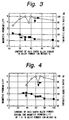
- the Inventor also conducted an experiment about magnetic permeability and theoretic density ratio of targets upon rare earth alloy powder contained in alloy powder, using targets prepared by using rare earth alloy powder.
- a result of the experiment is shown in Fig. 3.
- values of magnetic permeability of targets are plotted with ⁇ whereas values of theoretic density ratio are plotted with ⁇ .
- permeability of targets is larger than 2 when the content of rare earth alloy powder in alloy powder is less than 65 weight %, and becomes 2 or less when the content of the rare earth alloy powder in alloy powder is not less than 65 weight %, or preferably not less than 70 weight %, taking errors into account.
- content of rare earth alloy powder in alloy powder as the source material of a target should be not less than 65 weight %, and more preferably not less than 70 weight %.
- Fig. 4 shows dependency of magnetic permeability and theoretic density ratio of targets upon content of rare earth alloy powder in alloy powder, when magnetic permeability of the rare earth alloy powder is controlled not to exceed 2 (more specifically around 1.5).
- values of magnetic permeability of targets are plotted with ⁇ whereas values of theoretic density ratio are plotted with ⁇ .
- content of rare earth alloy powder having a magnetic permeability not higher than 2 in alloy powder used as the source material of targets is preferably controlled not to be lower than 50 weight %.
- the Inventor has come to know that, in order to control magnetic permeability of a target not to exceed 2 while using recycled alloy powder, it is necessary to control the content of rare earth alloy powder including recycled alloy powder contained in alloy powder used as the source material of the target not to exceed 65 weight %.
- the invention has been made through those researches and accompanying experiments.
- a sputtering target made of alloy powder which contains at least 65 weight percent of at least one kind of rare earth alloy powder made of at least one kind of rare earth element and at least two kinds of elements selected from the group consisting of Fe, Co, Ni, Cr and Si, and contains at least one kind of recycled alloy powder prepared by using a target used at least once for sputtering.
- magnetic permeability of the target is typically a value not larger than 2.
- thickness of the target ensuring a sufficient leak magnetic flux intensity and enabling sputtering is typically not less than 8 mm and not more than 20 mm, or preferably not less than 10 mm and not more than 15 mm.
- a manufacturing method of a sputtering target which manufactures a target from alloy powder which contains at least 65 weight percent of at least one kind of rare earth alloy powder made of at least one kind of rare earth element and at least two kinds of elements selected from the group consisting of Fe, Co, Ni, Cr and Si, and contains at least one kind of recycled alloy powder prepared by using a target used at least once for sputtering.
- the recycled alloy powder is prepared by powdering by an atomizing method an ingot prepared by a target used at least once for sputtering and a material not used before for making a target.
- typically used as the atomizing method is a gas atomizing method.
- a single-roll method or a centrifugal disc method is also usable.
- recycled alloy powder is a substance obtained by powdering an ingot prepared from a target used at least once for sputtering, and a new material not used before for making a target.
- recycled alloy powder typically contains rare earth alloy powder prepared from a target used at least once for sputtering by 30 weight % or more, or preferably by 50 weight % or more.
- a rare earth element is the generic name of lanthanoids, Sc (scandium) and Y (yttrium) to lanthanoids. More specifically, it is the general name of La (lanthanum, Ce (cerium), Pr (praseodymium), Nd (neodymium), Pm (promethium), Sm (samarium), Eu (europium), Gd (gadolinium), Tb (terbium), Dy (dysprosium), Ho (holmium), Er (erbium), Tm (thulium), Yb (ytterbium), Lu (lutetium), Y and Sc.
- La lanthanum, Ce (cerium), Pr (praseodymium), Nd (neodymium), Pm (promethium), Sm (samarium), Eu (europium), Gd (gadolinium), Tb (terbium), Dy (dysprosium), Ho (holmium), Er (erbium), Tm (thul
- alloy powder typically contains 50 weight % or more of rare earth alloy powder having a magnetic permeability not larger than 2.
- content of rare earth metal in the rare earth alloy powder is typically not less than 30 weight %, and preferably not less than 35 weight %.
- magnetic permeability of alloy powder is controlled not to exceed 2.
- content of metal impurities in the target is typically not more than 0.1 weight %, and content of metal impurities in the alloy powder is not more than 0.1 weight %.
- theoretic density ratio of the target is typically not less than 97 %, and preferably not less than 98 %.
- the sputtering apparatus using the target is typically a magnetron sputtering apparatus.
- the target can be made in any other sputtering apparatus, such as opposed-electrodes sputtering apparatus, electron cyclotron resonance (ECR) sputtering apparatus, high-frequency sputtering apparatus, reactive sputtering apparatus, bias sputtering apparatus, collimate sputtering apparatus or long-distance (LD) sputtering apparatus.
- ECR electron cyclotron resonance
- LD long-distance
- the sputtering target is preferably made of alloy powder which contains at least one kind of rare earth alloy powder selected from the group consisting of FeTbCo, FeTbCr, FeTbCoCr, FeGdCo, FeDyCo and FeGdCoSi by 65 weight % or more, and containing at least one kind of recycled alloy powder prepared by using a target which is made of at least one kind of rare earth alloy selected from the group consisting of FeTbCo, FeTbCr, FeTbCoCr, FeGdCo, FeDyCo and FeGdCoSi used at least once for sputtering.
- the sputtering target is made of alloy powder which contains at least one kind of rare earth alloy powder made of at least one kind of rare earth element and at least two kinds of elements selected from the group consisting of Fe, Co, Ni, Cr and Si, and contains at least one kind of recycled alloy powder prepared from a target used at least once for sputtering, the sputtering target can be lowered in magnetic permeability, and increased in thickness.
- a target of a quaternary FeTbCoCr alloy used at least once for magnetron sputtering and new metals which are the same metals (Fe, Tb, Co, Cr) composing the quaternary alloy are blended to contain the used target by 30 weight % or more, such as 50 weight %, for example, in the first embodiment, and an ingot is made therefrom in a vacuum melting furnace (not shown). As explained later, this ingot is processed into recycled alloy powder containing rare earth alloy powder such that the content of rare earth metals in the rare earth alloy powder forming the recycled alloy powder is at least 35 weight %, such as 42 weight %, for example, in the first embodiment.
- the ingot is powdered in an inactive gas atmosphere like argon (Ar) gas by a gas atomizing process to prepare recycled alloy powder of FeTbCoCr alloy. Magnetic permeability of this recycled alloy powder has been confirmed to be 1.5 by measurement.
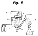
- a gas atomizing apparatus used for the gas atomizing process is explained below.
- the gas atomizing apparatus includes a vacuum melting furnace 1, granulating chamber 2, cyclone 3 and container 4 which are connected in sequence.
- the vacuum melting furnace 1 is a furnace for melting materials by high-frequency induction heating, for example.
- a nozzle 5 is provided directly under the vacuum melting furnace 1, and a gas inlet 6 for jetting a gas is provided neat the nozzle 5.
- the granulating chamber 2 is a processing chamber for powdering a material molten in the vacuum melting furnace 1 by spraying it in form of fine mist and thereby preparing a powder material.
- the cyclone 3 and the container 4 are used for storing a powdered material.
- recycled alloy powder of FeTbCoCr alloy is prepared.
- an ingot prepared from the used target and new metals of the same components is melted in the vacuum melting furnace 1.
- the molten material of the used target is continuously sprayed into the granulating chamber 2 from the vacuum melting furnace 1 through the nozzle 5, and an inactive gas such as Ar gas, for example, is jetted into the granulating chamber 2 through the gas inlet 6.
- an inactive gas such as Ar gas, for example
- the molten material in form of fine mist is quickly cooled and powdered into recycled alloy powder 7 while it falls down.
- the recycled alloy powder 7 is introduced into the cyclone 3.
- the recycled alloy powder 7 falls from the cyclone 3 into the container 4 and is stored there.
- Grain size and grain size profile of the globular grains 7 is controlled taking account of the temperature of the molten material, flow rate of the molten material from the nozzle 5, nozzle diameter, flow rate of the jetted inactive gas, and so forth. After that, the recycled alloy powder 7 is classified to form an optimum grain size profile.
- the recycled alloy powder 7 is blended with powder containing Fe, Tb, Co and Cr, for example, and by dry mixture thereof in an Ar gas atmosphere, alloy powder for manufacturing the target is prepared. Respective materials of this alloy powder are blended such that the alloy powder contains rare earth alloy powder by at least 65 weight %, or preferably by at least 70 weight %, and rare earth alloy powder having a magnetic permeability not larger than 2 by at least 50 weight %.
- the alloy powder is prepared to contain 80 weight %, for example, of recycled alloy powder having a magnetic permeability of 1.5 and contain another material as its remainder part, which is adjusted to make a predetermined target composition.
- the sputtering target is manufactured.
- a compression punch rod 13 is inserted into the carbon mold 12 from above the carbon mold and the mixed powder 10 supplied therein.
- the carbon mold 12 is set in a predetermined compression sintering apparatus (not shown), and heated and sintered there under a pressure applied onto the mixed powder 10 through the compression punch rod 13.
- the pressure is removed, and it is cooled.
- a sintered material 15 made by sintering the mixed powder 10 is removed from the carbon mold 12.
- the outer circumferential surface and top and bottom surfaces of the sintered material 15 prepared as explained above is cut approximately by 1 mm.
- the intended column-shaped sputtering target containing 66 atomic % of Fe, 24 atomic % of Tb, 7 atomic % of Co and 3 atomic % of Cr, and having the diameter of 127 mm and thickness of 10 mm, is obtained.
- the target prepared by the manufacturing method according to the first embodiment was confirmed to have the magnetic permeability of 1.2.
- theoretic density ratio, content of oxygen and content of metal impurities were also measured. As a result, theoretic density ratio was 97%, content of oxygen was 640 ppm, content of metal impurities was 660 ppm.
- magneto-optical recording mediums were actually made by magnetron sputtering using the target according to the first embodiment. As a result, productivity increased to approximately 1.8 times as compared with 8 mm thick targets by the conventional technique.
- the first embodiment by preparing recycled alloy powder having a magnetic permeability not larger than 2 from a used target of FeTbCoCr alloy used at least once for sputtering and a new metal with the same components by a gas atomizing method, thereafter preparing alloy powder containing 80 weight % of recycled alloy powder of FeTbCoCr alloy and not containing rare earth elements in the remainder part, and manufacturing a target from this alloy powder, it is possible to effectively use expensive rare earth elements while reducing metal contents and fabricate a target thick enough for sputtering and having a magnetic permeability controlled not to exceed 2. Therefore, the manufacturing cost of the target can be reduced, and the price of magneto-optical recording mediums manufactured by sputtering using this target can be reduced.
- the used target used in the second embodiment is made of a ternary FeTbCo alloy.
- a target of a FeTbCo alloy used at least once for magnetron sputtering and new metals of the same components are blended to contain the used target by 30 weight % or more, such as 50 weight %, for example, in the second embodiment, and an ingot is made therefrom in a vacuum melting furnace (not shown).
- this ingot is processed into recycled alloy powder containing rare earth alloy powder such that the content of rare earth metals in the rare earth alloy powder forming the recycled alloy powder is at least 35 weight %, such as 43 weight %, for example, in the second embodiment.
- the ingot is powdered in an inactive gas atmosphere by a gas atomizing process to prepare recycled alloy powder of FeTbCo alloy. Magnetic permeability of this recycled alloy powder has been confirmed to be 0.9 by measurement.
- the gas atomizing apparatus used for the gas atomizing process according to the second embodiment is the same as that used in the first embodiment, and its explanation is omitted here.
- the recycled alloy powder of FeTbCo is blended with powder of FeTbCo alloy not used before for making a target and other powder to make a predetermined target composition, and by dry mixture thereof in an Ar gas atmosphere, alloy powder for manufacturing the target is prepared.
- Respective materials of this alloy powder are blended such that the alloy powder contains rare earth alloy powder having a magnetic permeability not larger than 2 by at least 65 weight % and rare earth alloy powder by at least 65 weight %, or preferably by at least 70 weight %.
- the rare earth alloy powder is prepared such that it contains 50 weight %, for example, of recycled alloy powder including rare earth metals by 43 weight % and having the magnetic permeability of 0.9 whereas its remainder part is made of new rare earth alloy powder and powder of other materials adjusted to make a predetermined target composition and contains at least 70 weight % of rare alloy powder.
- mixed powder satisfying the above-indicated requirements is obtained. This mixed powder is adjusted to ensure that the target manufactured from this mixed powder contains 70 atomic % of Fe, 23 atomic % of Tb and 7 atomic % of Co.
- a sintered material is made by sintering in the same process as the first embodiment.
- the outer circumferential surface and top and bottom surfaces of the sintered material 15 prepared as explained above is cut approximately by 1 mm.
- the intended column-shaped sputtering target containing 70 atomic % of Fe, 23 atomic % of Tb and 7 atomic % of Co, for example, and having the diameter of 127 mm and thickness of 12 mm, is obtained.
- the sputtering target having a magnetic permeability not higher than 2 can be made, the same effects as those of the first embodiment can be obtained.
- FeTbCoCr is used as a quaternary rare earth alloy
- any other appropriate rare earth alloy such as FeGdCoSi can be used.
- FeTbCo is used as a ternary rare earth alloy
- FeTbCr, FeGdCo or FeDyCo may be used alternatively.
- the sputtering target is made of alloy powder which contains at least one kind of rare earth alloy powder made of at least one kind of rare earth element and at least two kinds of elements selected from the group consisting of Fe, Co, Ni, Cr and Si, and contains at least one kind of recycled alloy powder prepared from a target used at least once for sputtering, it is possible to effectively use expensive rare earth elements and reduce its manufacturing cost while reducing adverse affection to the environment. Additionally, since a sputtering target more reduced in magnetic permeability and having a larger thickness can be obtained, the price of magneto-optical recording mediums can be reduced.
Landscapes
- Chemical & Material Sciences (AREA)
- Chemical Kinetics & Catalysis (AREA)
- Engineering & Computer Science (AREA)
- Materials Engineering (AREA)
- Mechanical Engineering (AREA)
- Metallurgy (AREA)
- Organic Chemistry (AREA)
- Physical Vapour Deposition (AREA)
- Powder Metallurgy (AREA)
Applications Claiming Priority (2)
| Application Number | Priority Date | Filing Date | Title |
|---|---|---|---|
| JP26713699A JP4240679B2 (ja) | 1999-09-21 | 1999-09-21 | スパッタリング用ターゲットの製造方法 |
| JP26713699 | 1999-09-21 |
Publications (1)
| Publication Number | Publication Date |
|---|---|
| EP1087032A1 true EP1087032A1 (en) | 2001-03-28 |
Family
ID=17440590
Family Applications (1)
| Application Number | Title | Priority Date | Filing Date |
|---|---|---|---|
| EP00120582A Withdrawn EP1087032A1 (en) | 1999-09-21 | 2000-09-20 | Sputtering target and its manufacturing method |
Country Status (4)
| Country | Link |
|---|---|
| US (1) | US6409965B1 (enExample) |
| EP (1) | EP1087032A1 (enExample) |
| JP (1) | JP4240679B2 (enExample) |
| KR (1) | KR100714345B1 (enExample) |
Families Citing this family (46)
| Publication number | Priority date | Publication date | Assignee | Title |
|---|---|---|---|---|
| US6506289B2 (en) | 2000-08-07 | 2003-01-14 | Symmorphix, Inc. | Planar optical devices and methods for their manufacture |
| US20030002043A1 (en) * | 2001-04-10 | 2003-01-02 | Kla-Tencor Corporation | Periodic patterns and technique to control misalignment |
| US7469558B2 (en) | 2001-07-10 | 2008-12-30 | Springworks, Llc | As-deposited planar optical waveguides with low scattering loss and methods for their manufacture |
| JP2005508444A (ja) * | 2001-09-17 | 2005-03-31 | ヘラエウス インコーポレーテッド | 使用済みスパッタターゲットの再生 |
| US7404877B2 (en) | 2001-11-09 | 2008-07-29 | Springworks, Llc | Low temperature zirconia based thermal barrier layer by PVD |
| US7378356B2 (en) | 2002-03-16 | 2008-05-27 | Springworks, Llc | Biased pulse DC reactive sputtering of oxide films |
| US6884327B2 (en) | 2002-03-16 | 2005-04-26 | Tao Pan | Mode size converter for a planar waveguide |
| US8445130B2 (en) | 2002-08-09 | 2013-05-21 | Infinite Power Solutions, Inc. | Hybrid thin-film battery |
| US8431264B2 (en) | 2002-08-09 | 2013-04-30 | Infinite Power Solutions, Inc. | Hybrid thin-film battery |
| US9793523B2 (en) | 2002-08-09 | 2017-10-17 | Sapurast Research Llc | Electrochemical apparatus with barrier layer protected substrate |
| US8394522B2 (en) | 2002-08-09 | 2013-03-12 | Infinite Power Solutions, Inc. | Robust metal film encapsulation |
| US8236443B2 (en) | 2002-08-09 | 2012-08-07 | Infinite Power Solutions, Inc. | Metal film encapsulation |
| US8021778B2 (en) | 2002-08-09 | 2011-09-20 | Infinite Power Solutions, Inc. | Electrochemical apparatus with barrier layer protected substrate |
| US20070264564A1 (en) | 2006-03-16 | 2007-11-15 | Infinite Power Solutions, Inc. | Thin film battery on an integrated circuit or circuit board and method thereof |
| US8404376B2 (en) | 2002-08-09 | 2013-03-26 | Infinite Power Solutions, Inc. | Metal film encapsulation |
| US7826702B2 (en) | 2002-08-27 | 2010-11-02 | Springworks, Llc | Optically coupling into highly uniform waveguides |
| US6863862B2 (en) * | 2002-09-04 | 2005-03-08 | Philip Morris Usa Inc. | Methods for modifying oxygen content of atomized intermetallic aluminide powders and for forming articles from the modified powders |
| EP1597408B1 (en) | 2003-02-27 | 2012-12-05 | Symmorphix, Inc. | Method for forming dielectric barrier layers |
| US8728285B2 (en) | 2003-05-23 | 2014-05-20 | Demaray, Llc | Transparent conductive oxides |
| US7238628B2 (en) | 2003-05-23 | 2007-07-03 | Symmorphix, Inc. | Energy conversion and storage films and devices by physical vapor deposition of titanium and titanium oxides and sub-oxides |
| US7504008B2 (en) * | 2004-03-12 | 2009-03-17 | Applied Materials, Inc. | Refurbishment of sputtering targets |
| US7959769B2 (en) | 2004-12-08 | 2011-06-14 | Infinite Power Solutions, Inc. | Deposition of LiCoO2 |
| CN101931097B (zh) | 2004-12-08 | 2012-11-21 | 希莫菲克斯公司 | LiCoO2的沉积 |
| US7838133B2 (en) | 2005-09-02 | 2010-11-23 | Springworks, Llc | Deposition of perovskite and other compound ceramic films for dielectric applications |
| US9127362B2 (en) | 2005-10-31 | 2015-09-08 | Applied Materials, Inc. | Process kit and target for substrate processing chamber |
| US8647484B2 (en) * | 2005-11-25 | 2014-02-11 | Applied Materials, Inc. | Target for sputtering chamber |
| US8062708B2 (en) | 2006-09-29 | 2011-11-22 | Infinite Power Solutions, Inc. | Masking of and material constraint for depositing battery layers on flexible substrates |
| US20080078268A1 (en) | 2006-10-03 | 2008-04-03 | H.C. Starck Inc. | Process for preparing metal powders having low oxygen content, powders so-produced and uses thereof |
| US8197781B2 (en) | 2006-11-07 | 2012-06-12 | Infinite Power Solutions, Inc. | Sputtering target of Li3PO4 and method for producing same |
| US20080145688A1 (en) | 2006-12-13 | 2008-06-19 | H.C. Starck Inc. | Method of joining tantalum clade steel structures |
| US8197894B2 (en) | 2007-05-04 | 2012-06-12 | H.C. Starck Gmbh | Methods of forming sputtering targets |
| US8968536B2 (en) | 2007-06-18 | 2015-03-03 | Applied Materials, Inc. | Sputtering target having increased life and sputtering uniformity |
| US7901552B2 (en) | 2007-10-05 | 2011-03-08 | Applied Materials, Inc. | Sputtering target with grooves and intersecting channels |
| US8268488B2 (en) | 2007-12-21 | 2012-09-18 | Infinite Power Solutions, Inc. | Thin film electrolyte for thin film batteries |
| JP5551612B2 (ja) | 2007-12-21 | 2014-07-16 | インフィニット パワー ソリューションズ, インコーポレイテッド | 電解質膜のための標的をスパッタリングする方法 |
| KR101606183B1 (ko) | 2008-01-11 | 2016-03-25 | 사푸라스트 리써치 엘엘씨 | 박막 배터리 및 기타 소자를 위한 박막 캡슐화 |
| US8350519B2 (en) | 2008-04-02 | 2013-01-08 | Infinite Power Solutions, Inc | Passive over/under voltage control and protection for energy storage devices associated with energy harvesting |
| US8906523B2 (en) | 2008-08-11 | 2014-12-09 | Infinite Power Solutions, Inc. | Energy device with integral collector surface for electromagnetic energy harvesting and method thereof |
| US8246903B2 (en) | 2008-09-09 | 2012-08-21 | H.C. Starck Inc. | Dynamic dehydriding of refractory metal powders |
| WO2010030743A1 (en) | 2008-09-12 | 2010-03-18 | Infinite Power Solutions, Inc. | Energy device with integral conductive surface for data communication via electromagnetic energy and method thereof |
| WO2010042594A1 (en) | 2008-10-08 | 2010-04-15 | Infinite Power Solutions, Inc. | Environmentally-powered wireless sensor module |
| CN102576828B (zh) | 2009-09-01 | 2016-04-20 | 萨普拉斯特研究有限责任公司 | 具有集成薄膜电池的印刷电路板 |
| US8894826B2 (en) * | 2009-09-24 | 2014-11-25 | Jesse A. Frantz | Copper indium gallium selenide (CIGS) thin films with composition controlled by co-sputtering |
| US20110300432A1 (en) | 2010-06-07 | 2011-12-08 | Snyder Shawn W | Rechargeable, High-Density Electrochemical Device |
| US8734896B2 (en) | 2011-09-29 | 2014-05-27 | H.C. Starck Inc. | Methods of manufacturing high-strength large-area sputtering targets |
| EP3807913A1 (en) * | 2018-06-18 | 2021-04-21 | ABB Schweiz AG | Method for producing a magnetic powder |
Citations (5)
| Publication number | Priority date | Publication date | Assignee | Title |
|---|---|---|---|---|
| EP0288010A2 (en) * | 1987-04-20 | 1988-10-26 | Hitachi Metals, Ltd. | Rare earth metal-iron group metal target, alloy powder therefor and method of producing same |
| EP0289315A2 (en) * | 1987-04-30 | 1988-11-02 | Sumitomo Metal Mining Company Limited | Alloy target for manufacturing a magneto-optical recording medium |
| US5710384A (en) * | 1995-03-08 | 1998-01-20 | Hitachi Metals, Ltd. | Magneto-optical recording medium target and manufacture method of same |
| JPH11189866A (ja) * | 1997-12-26 | 1999-07-13 | Mitsubishi Materials Corp | 希土類を含有する再生ターゲット材とその再生方法 |
| DE19922144A1 (de) * | 1998-05-12 | 1999-11-25 | Sumitomo Metal Mining Co | Verfahren zur Gewinnung einer Wertstoffzusammensetzung aus Seltenerdelement-enthaltendem Material und dabei erhaltenes Legierungspulver |
Family Cites Families (1)
| Publication number | Priority date | Publication date | Assignee | Title |
|---|---|---|---|---|
| JP3098204B2 (ja) * | 1997-03-07 | 2000-10-16 | ティーディーケイ株式会社 | 光磁気記録用合金ターゲット、その製造方法およびその再生方法 |
-
1999
- 1999-09-21 JP JP26713699A patent/JP4240679B2/ja not_active Expired - Lifetime
-
2000
- 2000-09-20 EP EP00120582A patent/EP1087032A1/en not_active Withdrawn
- 2000-09-21 US US09/666,241 patent/US6409965B1/en not_active Expired - Lifetime
- 2000-09-21 KR KR1020000055414A patent/KR100714345B1/ko not_active Expired - Lifetime
Patent Citations (5)
| Publication number | Priority date | Publication date | Assignee | Title |
|---|---|---|---|---|
| EP0288010A2 (en) * | 1987-04-20 | 1988-10-26 | Hitachi Metals, Ltd. | Rare earth metal-iron group metal target, alloy powder therefor and method of producing same |
| EP0289315A2 (en) * | 1987-04-30 | 1988-11-02 | Sumitomo Metal Mining Company Limited | Alloy target for manufacturing a magneto-optical recording medium |
| US5710384A (en) * | 1995-03-08 | 1998-01-20 | Hitachi Metals, Ltd. | Magneto-optical recording medium target and manufacture method of same |
| JPH11189866A (ja) * | 1997-12-26 | 1999-07-13 | Mitsubishi Materials Corp | 希土類を含有する再生ターゲット材とその再生方法 |
| DE19922144A1 (de) * | 1998-05-12 | 1999-11-25 | Sumitomo Metal Mining Co | Verfahren zur Gewinnung einer Wertstoffzusammensetzung aus Seltenerdelement-enthaltendem Material und dabei erhaltenes Legierungspulver |
Non-Patent Citations (1)
| Title |
|---|
| PATENT ABSTRACTS OF JAPAN vol. 1999, no. 12 29 October 1999 (1999-10-29) * |
Also Published As
| Publication number | Publication date |
|---|---|
| JP2001089849A (ja) | 2001-04-03 |
| JP4240679B2 (ja) | 2009-03-18 |
| KR100714345B1 (ko) | 2007-05-03 |
| KR20010030459A (ko) | 2001-04-16 |
| US6409965B1 (en) | 2002-06-25 |
Similar Documents
| Publication | Publication Date | Title |
|---|---|---|
| US6409965B1 (en) | Sputtering target and its manufacturing method | |
| EP1705670B1 (en) | Functionally graded rare earth permanent magnet | |
| US10160037B2 (en) | Rare earth magnet and its preparation | |
| US10242778B2 (en) | Manufacturing method of rare earth magnet based on heat treatment of fine powder | |
| EP0411591B2 (en) | Cold accumulating material | |
| US10672546B2 (en) | R-T-B based permanent magnet | |
| US10943717B2 (en) | R-T-B based permanent magnet | |
| CN108417334B (zh) | R-t-b系烧结磁铁 | |
| JP5348124B2 (ja) | R−Fe−B系希土類焼結磁石の製造方法およびその方法によって製造された希土類焼結磁石 | |
| US20150357119A1 (en) | Manufacturing methods of a powder for rare earth magnet and the rare earth magnet based on evaporation treatment | |
| JPH0768612B2 (ja) | 希土類金属―鉄族金属ターゲット用合金粉末、希土類金属―鉄族金属ターゲット、およびそれらの製造方法 | |
| EP2740551B1 (en) | Alloy flakes as starting material for rare earth sintered magnet | |
| CN114255949A (zh) | 磁性材料及其制造方法 | |
| KR0129795B1 (ko) | 광자기 기록 매체용 타겟 및 그 제조 방법 | |
| JP2533922B2 (ja) | 焼結タ―ゲット部材およびその製造方法 | |
| EP0286324A1 (en) | Magnets | |
| JP2001192709A (ja) | リサイクル合金粉末およびその製造方法 | |
| US12505940B2 (en) | Rare earth magnet and manufacturing method therefor | |
| JP2894695B2 (ja) | 希土類金属−鉄族金属ターゲットおよびその製造方法 | |
| JP7648429B2 (ja) | スパッタリングターゲット部材、スパッタリングターゲット組立品、及び成膜方法 | |
| JPH07201545A (ja) | 焼結磁石およびその製造方法 | |
| JPS59229461A (ja) | 高保磁力磁性合金粉末 | |
| CN114446564B (zh) | 稀土磁体及其制造方法 | |
| JP7518754B2 (ja) | R‐t‐b系永久磁石 | |
| JP6256140B2 (ja) | R−t−b系焼結磁石 |
Legal Events
| Date | Code | Title | Description |
|---|---|---|---|
| PUAI | Public reference made under article 153(3) epc to a published international application that has entered the european phase |
Free format text: ORIGINAL CODE: 0009012 |
|
| AK | Designated contracting states |
Kind code of ref document: A1 Designated state(s): DE FR GB |
|
| AX | Request for extension of the european patent |
Free format text: AL;LT;LV;MK;RO;SI |
|
| 17P | Request for examination filed |
Effective date: 20010828 |
|
| AKX | Designation fees paid |
Free format text: DE FR GB |
|
| 17Q | First examination report despatched |
Effective date: 20070521 |
|
| STAA | Information on the status of an ep patent application or granted ep patent |
Free format text: STATUS: THE APPLICATION IS DEEMED TO BE WITHDRAWN |
|
| 18D | Application deemed to be withdrawn |
Effective date: 20071002 |