EP1085952B1 - Vorrichtung zur herstellung einer nietverbindung und zugehöriger niet - Google Patents
Vorrichtung zur herstellung einer nietverbindung und zugehöriger niet Download PDFInfo
- Publication number
- EP1085952B1 EP1085952B1 EP99927868A EP99927868A EP1085952B1 EP 1085952 B1 EP1085952 B1 EP 1085952B1 EP 99927868 A EP99927868 A EP 99927868A EP 99927868 A EP99927868 A EP 99927868A EP 1085952 B1 EP1085952 B1 EP 1085952B1
- Authority
- EP
- European Patent Office
- Prior art keywords
- rivet
- sleeve
- pin
- mandrel
- piston
- Prior art date
- Legal status (The legal status is an assumption and is not a legal conclusion. Google has not performed a legal analysis and makes no representation as to the accuracy of the status listed.)
- Expired - Lifetime
Links
- 238000010304 firing Methods 0.000 claims abstract description 19
- 230000009471 action Effects 0.000 claims description 6
- 238000000034 method Methods 0.000 description 13
- 230000008569 process Effects 0.000 description 13
- 230000008901 benefit Effects 0.000 description 9
- 230000006378 damage Effects 0.000 description 5
- 238000005520 cutting process Methods 0.000 description 4
- 238000004519 manufacturing process Methods 0.000 description 4
- 238000003780 insertion Methods 0.000 description 3
- 230000037431 insertion Effects 0.000 description 3
- 239000004033 plastic Substances 0.000 description 3
- 238000007789 sealing Methods 0.000 description 3
- 230000001960 triggered effect Effects 0.000 description 3
- 229910000831 Steel Inorganic materials 0.000 description 2
- 230000000694 effects Effects 0.000 description 2
- 238000009527 percussion Methods 0.000 description 2
- 238000003892 spreading Methods 0.000 description 2
- 230000007480 spreading Effects 0.000 description 2
- 239000010935 stainless steel Substances 0.000 description 2
- 229910001220 stainless steel Inorganic materials 0.000 description 2
- 239000010959 steel Substances 0.000 description 2
- 235000001674 Agaricus brunnescens Nutrition 0.000 description 1
- 229910000838 Al alloy Inorganic materials 0.000 description 1
- 229910000881 Cu alloy Inorganic materials 0.000 description 1
- 208000027418 Wounds and injury Diseases 0.000 description 1
- 238000004026 adhesive bonding Methods 0.000 description 1
- XAGFODPZIPBFFR-UHFFFAOYSA-N aluminium Chemical compound [Al] XAGFODPZIPBFFR-UHFFFAOYSA-N 0.000 description 1
- 238000005452 bending Methods 0.000 description 1
- 230000015572 biosynthetic process Effects 0.000 description 1
- 230000003139 buffering effect Effects 0.000 description 1
- 235000013351 cheese Nutrition 0.000 description 1
- 238000011109 contamination Methods 0.000 description 1
- 238000005553 drilling Methods 0.000 description 1
- 239000002360 explosive Substances 0.000 description 1
- 239000012530 fluid Substances 0.000 description 1
- 239000010720 hydraulic oil Substances 0.000 description 1
- 208000014674 injury Diseases 0.000 description 1
- 238000009434 installation Methods 0.000 description 1
- 238000009413 insulation Methods 0.000 description 1
- 230000003993 interaction Effects 0.000 description 1
- 239000000463 material Substances 0.000 description 1
- 229910052751 metal Inorganic materials 0.000 description 1
- 239000002184 metal Substances 0.000 description 1
- 230000035515 penetration Effects 0.000 description 1
- 238000003825 pressing Methods 0.000 description 1
- 238000005096 rolling process Methods 0.000 description 1
- 238000007493 shaping process Methods 0.000 description 1
- 239000007858 starting material Substances 0.000 description 1
- 238000003466 welding Methods 0.000 description 1
Images

Classifications
-
- F—MECHANICAL ENGINEERING; LIGHTING; HEATING; WEAPONS; BLASTING
- F16—ENGINEERING ELEMENTS AND UNITS; GENERAL MEASURES FOR PRODUCING AND MAINTAINING EFFECTIVE FUNCTIONING OF MACHINES OR INSTALLATIONS; THERMAL INSULATION IN GENERAL
- F16B—DEVICES FOR FASTENING OR SECURING CONSTRUCTIONAL ELEMENTS OR MACHINE PARTS TOGETHER, e.g. NAILS, BOLTS, CIRCLIPS, CLAMPS, CLIPS OR WEDGES; JOINTS OR JOINTING
- F16B19/00—Bolts without screw-thread; Pins, including deformable elements; Rivets
- F16B19/04—Rivets; Spigots or the like fastened by riveting
- F16B19/08—Hollow rivets; Multi-part rivets
- F16B19/086—Self-piercing rivets
-
- B—PERFORMING OPERATIONS; TRANSPORTING
- B21—MECHANICAL METAL-WORKING WITHOUT ESSENTIALLY REMOVING MATERIAL; PUNCHING METAL
- B21J—FORGING; HAMMERING; PRESSING METAL; RIVETING; FORGE FURNACES
- B21J15/00—Riveting
- B21J15/02—Riveting procedures
- B21J15/025—Setting self-piercing rivets
-
- B—PERFORMING OPERATIONS; TRANSPORTING
- B21—MECHANICAL METAL-WORKING WITHOUT ESSENTIALLY REMOVING MATERIAL; PUNCHING METAL
- B21J—FORGING; HAMMERING; PRESSING METAL; RIVETING; FORGE FURNACES
- B21J15/00—Riveting
- B21J15/02—Riveting procedures
- B21J15/04—Riveting hollow rivets mechanically
- B21J15/043—Riveting hollow rivets mechanically by pulling a mandrel
-
- B—PERFORMING OPERATIONS; TRANSPORTING
- B21—MECHANICAL METAL-WORKING WITHOUT ESSENTIALLY REMOVING MATERIAL; PUNCHING METAL
- B21J—FORGING; HAMMERING; PRESSING METAL; RIVETING; FORGE FURNACES
- B21J15/00—Riveting
- B21J15/10—Riveting machines
- B21J15/105—Portable riveters
-
- Y—GENERAL TAGGING OF NEW TECHNOLOGICAL DEVELOPMENTS; GENERAL TAGGING OF CROSS-SECTIONAL TECHNOLOGIES SPANNING OVER SEVERAL SECTIONS OF THE IPC; TECHNICAL SUBJECTS COVERED BY FORMER USPC CROSS-REFERENCE ART COLLECTIONS [XRACs] AND DIGESTS
- Y10—TECHNICAL SUBJECTS COVERED BY FORMER USPC
- Y10T—TECHNICAL SUBJECTS COVERED BY FORMER US CLASSIFICATION
- Y10T29/00—Metal working
- Y10T29/53—Means to assemble or disassemble
- Y10T29/53709—Overedge assembling means
- Y10T29/53717—Annular work
- Y10T29/53726—Annular work with second workpiece inside annular work one workpiece moved to shape the other
- Y10T29/5373—Annular work with second workpiece inside annular work one workpiece moved to shape the other comprising driver for snap-off-mandrel fastener; e.g., Pop [TM] riveter
- Y10T29/53752—Annular work with second workpiece inside annular work one workpiece moved to shape the other comprising driver for snap-off-mandrel fastener; e.g., Pop [TM] riveter having rotary drive mechanism
Definitions
- the invention relates to a device for producing a riveted joint with means for shooting and pulling the rivet according to the preamble of Claim 1 and a rivet associated with this device.
- rivet connections are used to connect Workpieces used, especially of sheet metal, especially when the workpieces to be connected are only accessible from one side.
- Typical areas of application are the installation of fittings, Cassette walls or edge parts on insulation panels in industrial and Hall.
- the sheets to be joined have a thickness of 0.1 mm to about 3 mm, typically about 0.75 mm.
- Rivets with rivet mandrels are pierced through the workpieces and the Rivet with the rivet sleeve up to the stop of a stop head Rivet sleeve pressed into the hole at the edge of the hole.
- Rivets with rivet mandrels are pierced through the workpieces and the Rivet with the rivet sleeve up to the stop of a stop head Rivet sleeve pressed into the hole at the edge of the hole.
- the rivet connection between the workpieces is then under Hold the stop head of the rivet mandrel in the direction of insertion pulled in the opposite direction, which is the stop head opposite end of the rivet sleeve forming an expansion deformed so that the workpieces to be connected between the stop head and the expansion created become.
- This type of rivet is often referred to as a "blind rivet".
- EP 0 302 128 B1 shows a tool for pulling or setting Blind rivets. Even when using such a tool is
- WO 95/05255 shows a device for producing a Rivet connection with pneumatically driven means for shooting a Rivets through workpieces to be connected and pneumatically driven Means for subsequently pulling the rivet.
- the means of shooting the Rivets act using a conically tapering, hollow cylindrical driving part on the stop head of the rivet sleeve.
- the Rivet mandrel is through an opening in the rivet's stop head facing stop surface of the driving part in the interior of the driving part out there and in the weft direction behind the driving part arranged means for pulling the rivet detected.
- GB-A-1,128,442 shows an apparatus for producing a Rivet connection with means for driving in a rivet sleeve and one through the rivet mandrel guided rivet connecting workpieces and with means for pulling the rivet, wherein the means for driving in the rivet act on the mandrel and in a shooting bolt and a cylindrical part between the rivet and have a cylindrical impact piece arranged on the shooting bolt, which has a shoulder on which the firing pin strikes. If the Rivet not far with its mandrel when inserted into the device enough until it is in contact with a contact strip of the striking piece is and / or by handling the device and thus associated movements of the rivet mandrel moved away from the contact strip the opening of the Percussion on the mandrel. This often leads to an undesirable one Deformation of the rivet mandrel and / or damage to the impact piece.
- the present invention is therefore based on the problem of a To provide a device for producing a riveted joint, which overcomes the disadvantages of the prior art and in particular one Prevents deformation of the rivet mandrel and / or the striker and thereby a higher functional reliability and a longer lifespan of the Device causes.
- the device should be inexpensive is producible and ensures reliable operation.
- the constructive effort for the provision of means to pull and Means for shooting the rivet should be as low as possible, in particular, a realization with a small size should be possible.
- a rivet that can be processed with this device is to be provided become.
- the problem is solved in that the striking piece in the cylindrical Part by an elastic element, in particular by a first Coil spring is held in axial contact on the rivet mandrel. That has the advantage that the striking piece already bears against the mandrel if the firing pin strikes the striker. This will make one Damage, especially bending, the mandrel and the Impact piece due to the impact of the impact piece on the Rivet mandrel reliably prevented. It also becomes a Prevents the torn rivet mandrel from falling into the firing channel, and the device can be operated in any position, in particular can Rivets can also be placed vertically upwards.
- the means for driving or shooting the rivet on the The mandrel can act advantageously on the means for pulling the rivet Shot direction before the means for shooting the rivet on the mandrel attack.
- the constructive design scope for realizing the This increases the means for pulling the rivet and a corresponding one Device can be made small and easy.
- Shooting the rivet acting on the mandrel also increases the reliability of the manufactured rivet connection, as a safe puncture of the connecting workpieces is ensured by means of the rivet mandrel.
- the means of shooting and means of pulling the rivet can pneumatic, hydraulic, magnetic, electrical, piezoelectric or be drivable using an explosive.
- the device according to claim 2 has the advantage that for example trough-shaped and facing the striking piece Centering device adapted to the reliability of the end of the mandrel Shooting is further increased. In particular, this is also common desired right-angled alignment of the rivet mandrel with respect to the connecting workpieces and a corresponding guidance of the rivet guaranteed during the shooting process.
- the device according to claim 3 has the advantage that the movement of the striker at the end of the shooting process is gently braked by the elastic buffer element and in particular does not strike the end of the preferably metallic firing channel. This significantly increases the service life of the device.
- the buffer element preferably abuts an annular shoulder at the end of the weft channel, which is formed by an opening in the weft channel, and can be designed, for example, as a coil spring, plate spring or rubber or plastic disk.
- the device according to claim 4 has the advantage that the two-part formation of the shot channel by a hollow piston and a connecting piece, which are preferably screwed together, the firing channel is easily accessible and in particular the striking piece can be replaced if necessary.
- the device according to claim 5 has the advantage that Tail not only a guide of the rivet mandrel during the shooting and Pulling takes place, but that the end piece at the same time Spreading of the jaws guaranteed during the shooting process and thus a smooth passage of the rivet mandrel and if necessary the striker through the jaws during the shooting process is guaranteed. At the same time there is damage to the jaws through the rivet mandrel and possibly the striking piece during the Shooting reliably prevented. It is also due to the spread the clamping jaw simplifies the insertion of a new rivet.
- the second elastic element can be designed as a coil spring. alternative this comes for example a disc spring or a rubber or Plastic disc into consideration.
- the device according to claim 6 has the advantage that interconnected, preferably screwed together, Piston, connector and adapter sleeve pull the mandrel by pressurizing the piston against the force of a elastic element, preferably a coil spring with high Spring constant, reliable pulling of the rivet and therefore one reliable manufacture of the. Rivet connection is guaranteed.
- the Pressurization is preferably done using a hydraulic pressure to provide the required high forces.
- the device according to claim 7 has the advantage that the device only one supply connection, namely a compressed air connection is required.
- the hydraulic pressure is provided via a pneumatic / hydraulic pressure converter.
- the rivet is fired pneumatic, the rivet pulled hydraulically.
- the entire riveting process with shooting and pulling is done by a three-stage pneumatic Switching element controlled.
- the pneumatic / hydraulic pressure converter is just like the quick exhaust valve, preferably in one hand the device housed.
- a rivet according to is suitable for use in the device according to the invention Claim 8 provided.
- Through the pyramid-shaped tip of the rivet mandrel For example, four cutting edges are provided that penetrate simplify the workpieces.
- the hooking means can For example, by distributed over the circumference of the rivet mandrel and radially projecting mandrels or by axially successive, frustoconical and by rolling manufactured sections of the rivet mandrel can be realized.
- the mandrel is preferably made of steel or stainless steel.
- the rivet sleeve can also consist of steel or stainless steel or alternatively of an aluminum or copper alloy.
- the rivet according to claim 9 has the advantage that also by tapered second end of the rivet mandrel with a secure interaction the centering device on the hammer is guaranteed.
- An arrangement the second end in the form of a pyramid advantageously already results by appropriately separating a rivet mandrel from one rod-shaped starting material.
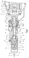
- Fig. 1 shows a section through the head part of the invention Device responsible for shooting and pulling the rivet.
- the housing 1 of the device On the right edge of the picture, the housing 1 of the device is shown on which using a sealing first O-ring 2 and one Support disc 24 of the first cylinder 22 by means of cheese head screws 6 and Washers 23 is screwed on.
- the shot channel 70 extends axially Extension of the firing pin 25 and is by the centering piece 45, the hollow piston 20 and the connector 18 are formed.
- the piston 20 is screwed to the connector 18 and to the Centering piece 45 by a tight fit and under the action of force third helical spring 8 designed as a third elastic element connected.
- the piston 20 is by means of the third coil spring 8 supported at one end on the support plate 24 and at the other end on Centering piece 45 supports, in the direction of that shown on the left edge of the picture Rivet 14 preloaded.
- the piston 20 is in the first cylinder 22 through a guide ring 13 and guided and sealed a first seal combination 12.
- Hydraulic connection 69 is hydraulic oil via an annular groove and corresponding holes in the first guide bush 26 on one Circlip 5 over into the hollow cylindrical volume between the first Cylinder 22 and piston 20 are supplied and the piston 20 is at appropriate pressurization of, for example, 200 bar against the action of the third coil spring 8 in the first cylinder 22 displaceable.
- Another hydraulic connection of the first cylinder 22 is stuffed blind by the first screw 56.
- the piston 20 is through a second seal combination 11 and one axially adjacent third O-ring 10 at the rivet-side end of the first cylinder 22 again guided and sealed.
- the seal combinations 11, 12, 35 are multi-part and have a plastic part with a sealing lip and underlying O-ring.
- the piston 20 is connected to the connector 18 using a Lock nut 19 screwed.
- a Striker 21 guided, which by the first elastic element executed first coil spring 51 biased in the direction of the rivet 14 is.
- the first coil spring 51 is supported in the direction of the housing 1 on one formed in the firing channel by the piston 20 annular shoulder and is supported in the direction of the rivet 14 on the Hammer 21 off.
- the striking piece 21 points to the first one Coil spring 51 facing end by forming a cylindrical extension with a smaller diameter also a annular shoulder on which the first coil spring 51 is supported.
- the striking piece 21 can be formed in one or more pieces, in particular, be in two parts.
- a two-piece Training can the hammer 21 from a sleeve and one in the Inserted sleeve and firmly connected to her mandrel, the compared to the sleeve a smaller diameter, a greater length and has a higher modulus of elasticity and / or greater hardness.
- the firm connection between the sleeve and mandrel can for example Welding, pressing or gluing take place.
- the diameter of the Sleeve is adapted to the diameter of the shot channel 70 during the Diameter of the mandrel adapted to the diameter of the rivet mandrel 14b is.
- the striking piece 21 is located at an end of the Shot channel 70 arranged buffer element 49.
- the shot channel 70 is open through a hole in the connector 18 to the rivet 14, wherein in the illustrated embodiment, the striking piece 21 a first Section 21a, the diameter of which corresponds to the diameter of the Shot channel 70 is adapted and by means of which the striking piece 21 in Shot channel 70 is guided, and has a second section 21 b, whose smaller diameter to the diameter of the bore in Connection piece 18 or to the diameter of the rivet mandrel 14b is adjusted.
- the connector 18 is within one with the first cylinder 22 screwed guide sleeve 16 through an inserted in an annular groove sealed and guided second O-ring 9. With the connector 18 is still a clamping sleeve 4 screwed around the rivet mandrel 14b arranged around jaws 3 and also in the Guide sleeve 16 is guided.
- the jaws 3 are at their Housing 1 facing end by means of a pressure sleeve 17, the under Effect of a between the pressure sleeve 17 and the connector 18th arranged second coil spring 7 in the direction of the rivet 14 is biased, and at its end facing the rivet 14 by means of an end piece 15 screwed into the guide sleeve 16.
- the Spreading is carried out by form-fitting investment of cone-shaped end faces of the jaws 3 and the pressure sleeve 17 or the end piece 15.
- the second section 21 b of the striking piece 21 protrudes in the illustrated Position through the bore of the connector 18 and a bore in the pressure sleeve 17 to between the jaws 3 and lies on the Rivet mandrel 14b of the rivet 14.
- the second section 21b points at its a trough-shaped depression as the end facing the rivet mandrel 14b Centering device for the rivet mandrel 14b.
- the guide sleeve 16 is surrounded by a centering sleeve 54, one with the hole in the end piece 15 aligned opening for receiving the Has rivet mandrel 14b.
- the centering sleeve 54 is via first screws 52 and with the centering sleeve 54 or the second linkage 57 connected, preferably welded, nuts 53 with a first Linkage 55 and a second linkage 57 connected, which on a Switching element of the device acts such that the shooting process only can be triggered when the centering sleeve 54 by a Corresponding contact force on the device under contact of the rivet 14 to the workpieces to be connected and to the centering sleeve 54 axially in Direction of the housing 1 is pushed over the guide sleeve 16 and on this is pending. This will both reduce the risk of injury from shooting of a rivet without an appropriate attachment to a workpiece as well Empty shooting and the associated risk of damage to the Device effectively minimized.
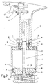
- Fig. 2 shows a section through the handle 71 of the device according to the invention.
- the compressed air connection 68 Device supplied with compressed air of, for example, 7 bar.
- About a that Shooting valve 59, pull valve 60 and trigger 61 comprehensive pneumatic switching element is the process of shooting and Pulling controlled.
- the one active while pulling the rivet pneumatic / hydraulic pressure converter is via a not shown Connection between the pull valve 60 and the input port 67 acted upon in the cover 34 with compressed air.
- the not shown Connection can, for example, be routed outside the handle Compressed air hoses or routed inside the handle Compressed air hoses or compressed air channels can be implemented.
- the cover 34 further includes a quick exhaust valve, which a sliding seal 48 and one by means of a ninth O-ring 64 sealed insert 46 with an axial bore includes.
- a quick exhaust valve On the outlet side of the quick exhaust valve is a with a second locking ring 63 secured sieve 47 is provided to a Prevent contamination of the quick exhaust valve.
- a connection of the quick exhaust valve is via a hole in the cover 34 with the second cylinder 32 of the pneumatic / hydraulic Pressure transducer connected.
- the cover 34 is made using a with screwed sealing flange 33 and seventh and eighth O-rings 39 and 62 connected to the second cylinder 32.
- a pneumatic piston 31 is arranged inside the second cylinder 32, by means of a sixth O-ring 38 inserted in an annular groove is sealed against the wall of the second cylinder 32.
- the piston rod 27 is also by a between the guide flange 30 and Handle 71 arranged guide bush 29 guided.
- the pneumatic pressure at the inlet port 67 into one hydraulic pressure in cavity 66 converted.
- the hydraulic Pressure is applied via the output port 65 to the one in FIG. 1 shown hydraulic connection 69 out.
- the not shown Pressure control on the hydraulic side can in turn, for example pressure lines routed outside the handle or the device or through pressure lines routed inside the device or Pressure channels can be realized.
- the guide flange 30 is by means of second screws 40 with the handle 71 tightly screwed using a fourth O-ring 36. At the same time, the flange 30 is connected to the second by an external thread Screwed cylinder 32. The flange 30 has a loading and Vent opening 74. On the flange 30 is still a annular second buffer 44 for buffering the pneumatic piston 31 an upward movement.
- the stop head 14e of the rivet sleeve 14a comes into contact with the centering sleeve 54 and pushes it further in the direction of the guide sleeve 16, whereby the pneumatic through the first and second linkages 55, 57 Switching element 59, 60, 61 is unlocked.
- the firing pin 25 moves forward hurled and strikes the striking piece 21, which hits the mandrel 14b acts and the rivet 14 in the workpieces to be connected he injected.
- the forward movement of the hammer 21 is thereby the buffer element 49 buffered within the firing channel 70.
- the hydraulic pressure acts on the piston 20 and presses it against the force the third coil spring 8 in the direction of the housing 1. This will also pulled the clamping sleeve 4 in the direction of the housing 1 and the jaws 3 firmly grip the rivet mandrel 14b and tear it away at the back at a predetermined breaking point.
- the trigger 61 is released, the in Fig. 2 input port 67 depressurized, causing the seal 48 falls from the insert 46 and the path of the compressed air from the second Cylinder 32 through the insert 46 and the sieve 47 to the environment releases.
- the second cylinder 32 is thereby depressurized.
- the mechanics of the pneumatic switching element 59, 60, 61 and with second linkage 57 that is operatively connected to it is designed that the shooting bolt 25 after a shot preferably in his Starting position returns and the pulling process is triggered several times is possible without an intermediate shooting process, as long as the machine is not lifted from the workpieces to be connected has been. This advantageously allows multiple pulls shot rivets and thus increases overall reliability and Operational safety of the device.
- FIG. 3 shows a schematic and partially sectioned Overall view of the device according to the invention.
- the illustrated Position of the rivet 14 with respect to the centering sleeve 54 and thus on the The head of the device corresponds to the illustration in FIG. 1.
- the position of the pneumatic piston 31 in the handle 71 corresponds to the illustration in FIG Fig. 2.
- the compressed air line 72 is by a dash-dotted line shown between the pull valve 60 and the input port 67.
- the hydraulic pressure line 73 is by a chain line between the output port 65 and the hydraulic port 69 shown.
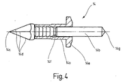
- Fig. 4 shows a rivet for use in the invention Contraption.
- the rivet 14 is constructed in two parts and has a rivet sleeve 14a and a rivet mandrel 14b.
- the rivet mandrel 14b is on its towards connecting workpieces directed first end with a tip 14c and provided with cutting edges 14d.
- A has proven to be particularly advantageous pyramid-shaped first end of the rivet mandrel 14b, whereby a total of four cutting edges 14d are formed.
- the rivet mandrel 14b partially surrounded by the rivet sleeve 14a, the rivet sleeve 14a is formed like a mushroom head at its end facing away from the tip 14c and forms a stop head 14e.
- rivet mandrel 14b is also preferred pyramid-shaped for reliable centering in relation to ensure the striking piece 21.
- the rivet mandrel 14b When the rivet 14 is fired, the rivet mandrel 14b together with the Rivet sleeve 14a driven into the workpieces to be connected, until the stop head 14e on one of the workpieces to be connected is applied.
- the Rivet mandrel 14b in the area of the rivet sleeve 14a on the tip 14c of the rivet 14 directed hooks.
- These can be, for example, by sawtooth-shaped, rolled-in ring grooves are formed, wherein the sawtooth shape is aligned such that the rivet mandrel 14b at Shoot the rivet 14 hooked in the rivet sleeve.
- the rivet sleeve 14a is firmly attached to the rivet mandrel 14b by hooking means connected, for example firmly pressed to the rivet mandrel 14b, soldered, glued or welded.
- the rivet mandrel 14b in Area of the rivet sleeve 14a on a predetermined breaking point 14f at which the rivet mandrel 14b tears when pulling the rivet 14.
Landscapes
- Engineering & Computer Science (AREA)
- Mechanical Engineering (AREA)
- General Engineering & Computer Science (AREA)
- Insertion Pins And Rivets (AREA)
Applications Claiming Priority (3)
| Application Number | Priority Date | Filing Date | Title |
|---|---|---|---|
| DE19826157 | 1998-06-12 | ||
| DE19826157A DE19826157A1 (de) | 1998-06-12 | 1998-06-12 | Vorrichtung zur Herstellung einer Nietverbindung und zugehöriger Niet |
| PCT/EP1999/003862 WO1999065629A1 (de) | 1998-06-12 | 1999-06-04 | Vorrichtung zur herstellung einer nietverbindung und zugehöriger niet |
Publications (2)
| Publication Number | Publication Date |
|---|---|
| EP1085952A1 EP1085952A1 (de) | 2001-03-28 |
| EP1085952B1 true EP1085952B1 (de) | 2002-10-09 |
Family
ID=7870663
Family Applications (1)
| Application Number | Title | Priority Date | Filing Date |
|---|---|---|---|
| EP99927868A Expired - Lifetime EP1085952B1 (de) | 1998-06-12 | 1999-06-04 | Vorrichtung zur herstellung einer nietverbindung und zugehöriger niet |
Country Status (5)
| Country | Link |
|---|---|
| US (1) | US6834420B1 (enExample) |
| EP (1) | EP1085952B1 (enExample) |
| JP (1) | JP4472871B2 (enExample) |
| DE (2) | DE19826157A1 (enExample) |
| WO (1) | WO1999065629A1 (enExample) |
Cited By (3)
| Publication number | Priority date | Publication date | Assignee | Title |
|---|---|---|---|---|
| DE102010039671A1 (de) * | 2010-08-24 | 2012-03-01 | Adolf Würth GmbH & Co. KG | Befestigungselement |
| DE102010039669A1 (de) * | 2010-08-24 | 2012-03-01 | Adolf Würth GmbH & Co. KG | Befestigungselement |
| DE102010039659A1 (de) * | 2010-08-24 | 2012-03-01 | Adolf Würth GmbH & Co. KG | Befestigungselement |
Families Citing this family (18)
| Publication number | Priority date | Publication date | Assignee | Title |
|---|---|---|---|---|
| DK1269029T3 (da) | 2000-03-29 | 2010-08-30 | Wuerth Int Ag | Blindnitte, nittedorn, holdindretning, fremgangsmåde til fremstilling af en blindnitte og fremgangsmåde til udførelse af en nitteforbindelse |
| GB2388412A (en) * | 2002-05-08 | 2003-11-12 | Emhart Llc | Blind rivet |
| ITBO20020619A1 (it) * | 2002-09-30 | 2004-04-01 | Far Srl | Pistola rivettatrice per rivetti filettati |
| DE20308754U1 (de) * | 2003-06-04 | 2003-07-31 | MBE Moderne Befestigungselemente GmbH, 58706 Menden | Großkopfniet mit Edelstahlkörper |
| DE102006002238C5 (de) * | 2006-01-17 | 2019-02-28 | Böllhoff Verbindungstechnik GmbH | Verfahren zum Herstellen einer Nagelverbindung sowie Nagel hierfür |
| MX2008010269A (es) * | 2006-02-12 | 2008-11-14 | Wuerth Adolf Gmbh & Co Kg | Remache de aplicacion neumatica o hidraulica. |
| DE202006013142U1 (de) * | 2006-08-26 | 2006-11-16 | Textron Verbindungstechnik Gmbh & Co. Ohg | Selbstbohrendes Blindniet |
| US20090031545A1 (en) * | 2007-08-01 | 2009-02-05 | Abeo, Llc | Rivet gun |
| JP2011157996A (ja) * | 2010-01-29 | 2011-08-18 | Nippon Pop Rivets & Fasteners Ltd | ブラインドリベット |
| DE102010039666A1 (de) * | 2010-08-24 | 2012-03-01 | Adolf Würth GmbH & Co. KG | Nietsetzgerät |
| US20120255336A1 (en) * | 2011-04-06 | 2012-10-11 | Chauncey Edward W | Systems and methods for corrugating a metallic tape |
| CN102430689B (zh) * | 2011-11-14 | 2013-12-18 | 宁波明润瑞达机械科技有限公司 | 一种用于管接头扣销钉的半自动化穿针装置 |
| DE102012106333A1 (de) * | 2012-07-02 | 2014-01-02 | Ejot Gmbh & Co. Kg | Verbindungselement zur Verbindung von zwei flachen Bauteilen |
| DE102013012222B4 (de) * | 2012-08-02 | 2020-12-03 | Richard Bergner Verbindungstechnik Gmbh & Co Kg | Vorrichtung sowie Verfahren zum reversiblen Greifen eines bolzenförmigen Elements, insbesondere eines Nietdorns |
| DE102013204734A1 (de) * | 2013-03-18 | 2014-10-02 | Adolf Würth GmbH & Co. KG | Schussniet |
| DE102014007555A1 (de) | 2014-05-22 | 2014-12-31 | Daimler Ag | System und Verfahren zum Fügen von zumindest zwei Bauteilen |
| US20160201709A1 (en) * | 2015-01-13 | 2016-07-14 | GM Global Technology Operations LLC | Rivet with cutting mandrel tip and one-sided joining method |
| DE102021214068A1 (de) * | 2021-12-09 | 2023-06-15 | Ejot Se & Co. Kg | Befestigungssystem und Verfahren zur Montage in einem Untergrund |
Family Cites Families (10)
| Publication number | Priority date | Publication date | Assignee | Title |
|---|---|---|---|---|
| DE606759C (de) * | 1930-12-18 | 1934-12-12 | Kathreiner G M B H | Vorrichtung zum Einschlagen von Naegeln |
| GB1128442A (en) * | 1964-10-03 | 1968-09-25 | Gkn Screws Fasteners Ltd | Improvements in or relating to methods of riveting and tubular rivet fastenings for use therein and in tools for use therewith |
| US3691924A (en) | 1970-05-18 | 1972-09-19 | William H Baker | Expansible drive rivet |
| DE2334385A1 (de) * | 1973-07-06 | 1975-01-23 | Hestermann Gerhard | Mietverbindungselemente zum blindnieten von blechen |
| EP0302128B1 (de) * | 1987-08-04 | 1992-01-02 | Maschinenbau Subotsch & Schwab Gmbh | Nietsetzwerkzeug zum Setzen von Blindnieten |
| US4990042A (en) * | 1989-09-05 | 1991-02-05 | Szayer Geza J | Self-drilling blind setting rivet |
| DE4215008C1 (de) * | 1992-05-06 | 1993-11-11 | Sfs Stadler Holding Ag Heerbru | Vorrichtung zum Setzen eines selbstbohrenden Klemmbefestigers |
| US5469610A (en) * | 1993-08-16 | 1995-11-28 | Courian; Curtis C. | Fastening tool and fastener |
| DE29514392U1 (de) * | 1995-09-07 | 1995-11-09 | Wirth Maschinenbau GmbH Innovative Hebe- und Fördertechnik, 06188 Landsberg | Blindniet und Vorrichtung für dessen Verarbeitung |
| DE19652031A1 (de) * | 1996-12-13 | 1998-06-18 | Bosch Siemens Hausgeraete | Niet |
-
1998
- 1998-06-12 DE DE19826157A patent/DE19826157A1/de not_active Withdrawn
-
1999
- 1999-06-04 US US09/719,009 patent/US6834420B1/en not_active Expired - Fee Related
- 1999-06-04 EP EP99927868A patent/EP1085952B1/de not_active Expired - Lifetime
- 1999-06-04 JP JP2000554494A patent/JP4472871B2/ja not_active Expired - Fee Related
- 1999-06-04 DE DE59903030T patent/DE59903030D1/de not_active Expired - Lifetime
- 1999-06-04 WO PCT/EP1999/003862 patent/WO1999065629A1/de not_active Ceased
Cited By (3)
| Publication number | Priority date | Publication date | Assignee | Title |
|---|---|---|---|---|
| DE102010039671A1 (de) * | 2010-08-24 | 2012-03-01 | Adolf Würth GmbH & Co. KG | Befestigungselement |
| DE102010039669A1 (de) * | 2010-08-24 | 2012-03-01 | Adolf Würth GmbH & Co. KG | Befestigungselement |
| DE102010039659A1 (de) * | 2010-08-24 | 2012-03-01 | Adolf Würth GmbH & Co. KG | Befestigungselement |
Also Published As
| Publication number | Publication date |
|---|---|
| EP1085952A1 (de) | 2001-03-28 |
| DE59903030D1 (de) | 2002-11-14 |
| US6834420B1 (en) | 2004-12-28 |
| JP4472871B2 (ja) | 2010-06-02 |
| WO1999065629A1 (de) | 1999-12-23 |
| JP2002518179A (ja) | 2002-06-25 |
| DE19826157A1 (de) | 1999-12-23 |
Similar Documents
| Publication | Publication Date | Title |
|---|---|---|
| EP1085952B1 (de) | Vorrichtung zur herstellung einer nietverbindung und zugehöriger niet | |
| DE60313261T2 (de) | Selbststanzender Blindbefestiger | |
| DE69317303T3 (de) | Selbststanzende nieten | |
| DE10031073B4 (de) | Verfahren zum Vernieten | |
| EP1132160B1 (de) | Pneumatisch-hydraulisches Blindnietgerät | |
| EP1984634A2 (de) | Blindniet und vorrichtung hierfür | |
| EP2283965A1 (de) | Funktionselement, Verfahren zum Einbringen des Funktionselementes in ein Blechteil sowie Zusammenbauteil | |
| DE2309353A1 (de) | Nietvorrichtung | |
| WO2012120132A1 (de) | Mundstück für ein nietgerät, nietgerät sowie verfahren zum vernieten eines werkstückes | |
| DE3219618C2 (de) | Werkzeug zum Spalten oder Sprengen von Gestein | |
| DE10033152A1 (de) | Verfahren zur Anbringung eines Funktionselementes; Matrize; Funktionselement; Zusammenbauteil und Stempelanordnung | |
| DE632529C (de) | Nietmaschine zum Schliessen durch Stauchen eines von einem Schliessbolzen durchsetzten Hohlnietes | |
| DE102011103723A1 (de) | Verbindungsanordnung, insbesondere für Flugzeugstrukturteile | |
| DE10258238B4 (de) | Nagelschraube zur Herstellung einer Fügeverbindung, sowie ein Fügeverfahren unter Verwendung der Nagelschraube und eine Vorrichtung zur Durchführung des Fügeverfahrens | |
| DE102006007707A1 (de) | Schussniet und Vorrichtung hierfür | |
| DE69608146T2 (de) | Verfahren zum Befestigen von Bauteilen und blinde Niete dafür | |
| DE10354680B4 (de) | Verfahren zum Verbinden von sich zumindest teilweise überlappenden Bauteilen | |
| EP1307316B1 (de) | Funktionsträgeranordnung, werkzeug zur anwendung mit der funktionsträgeranordnung sowie verfahren zum einsetzen der funktionsträgeranordnung in ein bauteil | |
| EP0038396B1 (de) | Einrichtung zur Positionierung eines Befestigungsmitteleintreibgerätes | |
| EP0995515B1 (de) | Vorrichtung zum mechanischen Fügen | |
| DE19701252C2 (de) | Verfahren und Verbindungsmittel zum Fügen von Blechen | |
| DE202004012269U1 (de) | Blindnietsetzgerät | |
| DE68901823T2 (de) | Vorrichtung zum setzen von befestigungselementen. | |
| DE10028858A1 (de) | Ausziehvorrichtung zum Entfernen eines ringförmigen Bauteils aus einer Bohrung | |
| EP3090835A1 (de) | Presswerkzeug und seine verwendung zum verpressen eines fittings |
Legal Events
| Date | Code | Title | Description |
|---|---|---|---|
| PUAI | Public reference made under article 153(3) epc to a published international application that has entered the european phase |
Free format text: ORIGINAL CODE: 0009012 |
|
| 17P | Request for examination filed |
Effective date: 20001116 |
|
| AK | Designated contracting states |
Kind code of ref document: A1 Designated state(s): CH DE FR GB IT LI |
|
| 17Q | First examination report despatched |
Effective date: 20010508 |
|
| GRAG | Despatch of communication of intention to grant |
Free format text: ORIGINAL CODE: EPIDOS AGRA |
|
| GRAG | Despatch of communication of intention to grant |
Free format text: ORIGINAL CODE: EPIDOS AGRA |
|
| GRAH | Despatch of communication of intention to grant a patent |
Free format text: ORIGINAL CODE: EPIDOS IGRA |
|
| GRAH | Despatch of communication of intention to grant a patent |
Free format text: ORIGINAL CODE: EPIDOS IGRA |
|
| GRAA | (expected) grant |
Free format text: ORIGINAL CODE: 0009210 |
|
| AK | Designated contracting states |
Kind code of ref document: B1 Designated state(s): CH DE FR GB IT LI |
|
| REG | Reference to a national code |
Ref country code: GB Ref legal event code: FG4D Free format text: NOT ENGLISH |
|
| REG | Reference to a national code |
Ref country code: CH Ref legal event code: NV Representative=s name: ISLER & PEDRAZZINI AG Ref country code: CH Ref legal event code: EP |
|
| REF | Corresponds to: |
Ref document number: 59903030 Country of ref document: DE Date of ref document: 20021114 |
|
| ET | Fr: translation filed | ||
| GBT | Gb: translation of ep patent filed (gb section 77(6)(a)/1977) |
Effective date: 20030205 |
|
| PLBE | No opposition filed within time limit |
Free format text: ORIGINAL CODE: 0009261 |
|
| STAA | Information on the status of an ep patent application or granted ep patent |
Free format text: STATUS: NO OPPOSITION FILED WITHIN TIME LIMIT |
|
| 26N | No opposition filed |
Effective date: 20030710 |
|
| REG | Reference to a national code |
Ref country code: CH Ref legal event code: PUE Owner name: ADOLF WUERTH GMBH & CO. KG Free format text: WIRTH GMBH#BREHNAER STRASSE 1#06188 LANDSBERG (DE) -TRANSFER TO- ADOLF WUERTH GMBH & CO. KG#REINHOLD-WUERTH-STRASSE 12-16,#D-74653 KUENZELSAU (DE) |
|
| REG | Reference to a national code |
Ref country code: FR Ref legal event code: TP |
|
| REG | Reference to a national code |
Ref country code: CH Ref legal event code: PCAR Free format text: ISLER & PEDRAZZINI AG;POSTFACH 1772;8027 ZUERICH (CH) |
|
| REG | Reference to a national code |
Ref country code: CH Ref legal event code: PUE Owner name: WUERTH INTERNATIONAL AG Free format text: ADOLF WUERTH GMBH & CO. KG#REINHOLD-WUERTH-STRASSE 12-16,#D-74653 KUENZELSAU (DE) -TRANSFER TO- WUERTH INTERNATIONAL AG#ASPERMONTSTRASSE 1#7000 CHUR (CH) |
|
| REG | Reference to a national code |
Ref country code: FR Ref legal event code: TP Owner name: WURTH INTERNATIONAL AG, CH Effective date: 20120625 |
|
| REG | Reference to a national code |
Ref country code: GB Ref legal event code: 732E Free format text: REGISTERED BETWEEN 20120913 AND 20120919 |
|
| REG | Reference to a national code |
Ref country code: GB Ref legal event code: 732E Free format text: REGISTERED BETWEEN 20121004 AND 20121010 |
|
| REG | Reference to a national code |
Ref country code: FR Ref legal event code: PLFP Year of fee payment: 17 |
|
| PGFP | Annual fee paid to national office [announced via postgrant information from national office to epo] |
Ref country code: CH Payment date: 20150618 Year of fee payment: 17 Ref country code: GB Payment date: 20150618 Year of fee payment: 17 Ref country code: DE Payment date: 20150619 Year of fee payment: 17 |
|
| PGFP | Annual fee paid to national office [announced via postgrant information from national office to epo] |
Ref country code: IT Payment date: 20150622 Year of fee payment: 17 Ref country code: FR Payment date: 20150619 Year of fee payment: 17 |
|
| REG | Reference to a national code |
Ref country code: DE Ref legal event code: R119 Ref document number: 59903030 Country of ref document: DE |
|
| REG | Reference to a national code |
Ref country code: CH Ref legal event code: PL |
|
| GBPC | Gb: european patent ceased through non-payment of renewal fee |
Effective date: 20160604 |
|
| REG | Reference to a national code |
Ref country code: FR Ref legal event code: ST Effective date: 20170228 |
|
| PG25 | Lapsed in a contracting state [announced via postgrant information from national office to epo] |
Ref country code: CH Free format text: LAPSE BECAUSE OF NON-PAYMENT OF DUE FEES Effective date: 20160630 Ref country code: FR Free format text: LAPSE BECAUSE OF NON-PAYMENT OF DUE FEES Effective date: 20160630 Ref country code: DE Free format text: LAPSE BECAUSE OF NON-PAYMENT OF DUE FEES Effective date: 20170103 Ref country code: LI Free format text: LAPSE BECAUSE OF NON-PAYMENT OF DUE FEES Effective date: 20160630 |
|
| PG25 | Lapsed in a contracting state [announced via postgrant information from national office to epo] |
Ref country code: GB Free format text: LAPSE BECAUSE OF NON-PAYMENT OF DUE FEES Effective date: 20160604 |
|
| PG25 | Lapsed in a contracting state [announced via postgrant information from national office to epo] |
Ref country code: IT Free format text: LAPSE BECAUSE OF NON-PAYMENT OF DUE FEES Effective date: 20160604 |