EP1077172A2 - Structure de carrosserie de véhicule automobile - Google Patents
Structure de carrosserie de véhicule automobile Download PDFInfo
- Publication number
- EP1077172A2 EP1077172A2 EP00117743A EP00117743A EP1077172A2 EP 1077172 A2 EP1077172 A2 EP 1077172A2 EP 00117743 A EP00117743 A EP 00117743A EP 00117743 A EP00117743 A EP 00117743A EP 1077172 A2 EP1077172 A2 EP 1077172A2
- Authority
- EP
- European Patent Office
- Prior art keywords
- members
- bent portions
- vehicle
- portions
- bent
- Prior art date
- Legal status (The legal status is an assumption and is not a legal conclusion. Google has not performed a legal analysis and makes no representation as to the accuracy of the status listed.)
- Granted
Links
Images


Classifications
-
- B—PERFORMING OPERATIONS; TRANSPORTING
- B62—LAND VEHICLES FOR TRAVELLING OTHERWISE THAN ON RAILS
- B62D—MOTOR VEHICLES; TRAILERS
- B62D21/00—Understructures, i.e. chassis frame on which a vehicle body may be mounted
- B62D21/15—Understructures, i.e. chassis frame on which a vehicle body may be mounted having impact absorbing means, e.g. a frame designed to permanently or temporarily change shape or dimension upon impact with another body
- B62D21/152—Front or rear frames
Definitions
- the object of the invention is to provide a vehicle body structure which can effectively absorb an applied shock load in the event of a rear-end crash while securing a sufficient width of the luggage space.
- each of the right and left rear side members extending back and forth on a vehicle body comprises a front member having a hat-shaped section opening upward and a rear member which has a section of a roughly U-shape and is opened upward, and the opening of which is covered by a plate.
- a first bent portion which bends toward the outside of the vehicle and a second bent portion which is positioned at the rear side of the first bent portion and bends toward the inside of the vehicle are continuously formed.
- a sufficient width of the luggage space is secured, and due to the closed sectional structure, the rear member having bent portions does not break at the bent portions in the event of a rear-end crash, whereby an applied shock load in the event of a rear-end crash can be effectively absorbed.
- the side wall of the rear member can be provided close to the side wall of the floor panel. Thereby, the angle of curvature at each bent portion of the rear member can be made smaller, whereby breakage of the rear member at the bent portions can be prevented in the event of a crash.
- the cross members connecting the rear members of the right and left rear side members can be formed so that both ends thereof increase in width, and both widened ends can be joined over the first bent portions and second bent portions of the rear members.
- bulkheads which have roughly U-shaped sections and are radially spread around the center of each bent portion can be disposed at the first and second bent portions of the rear member.
- Fig. 1 is a plan view showing the vehicle's rear side members.
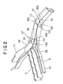
- Fig. 2 is a perspective view of one of the rear side members viewed from the rear side.
- right and left rear side members 1A and 1B extending back and forth at both sides of the vehicle body are comprised of front members 11 and rear members 12, and extended portions 121 having L-shaped sections extending from the front ends of the rear members 12 are joined to the rear end inner surfaces of the front members 11 which are formed so as to have hat-shaped sections opening upward.
- the rear members 12 have first bent portions 16 bending toward the outside of the vehicle and second bent portions 17 bending toward the inside of the vehicle at the middle portion so as to bend into a gentle S-shape as a whole, and the space between the right and left rear members 12 expands, and thereafter, the rear members extend substantially parallel to each other.
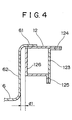
- the sectional structure of the rear members is formed into a closed section so that, as shown in Fig. 3 and Fig. 4, a flat plate 123 is joined to the flange portion so as to cover the opening of the rear member 12 formed to have an U-shaped section opening upward.
- upper edge 61 of floor panel 6 (Fig. 4) which is formed into a container shape is joined onto the top surface of the rear member 12.
- the plate 123 inclines so as not to partially interfere with the rear wheel shock absorber (Fig. 3).
- the right and left rear side members 1A and 1B are connected to each other at three points back and forth by the cross members 3, 4, and 5 extending in the direction of the vehicle's width.
- the cross member 5 is comprised of middle member 51 positioned at the middle portion in the direction of the vehicle width, and end members 52 positioned at both ends of the middle member 51.
- the members 51 and 52 is formed so as to have a hat-shaped section opening upward, the end members 52 are formed into generally triangle shapes which gradually widen toward the rear members 12 in the plan view, and the widened front ends are joined to the inner surfaces from the first bent portions 16 to the second bent portions 17 of the rear members 12.
- flanges 521 (Fig. 1) are projectingly formed, which are joined to the lower surfaces of the rear members 12 (Fig. 3).
- the bulkheads 14 and 15 are inserted inside the space of the closed section of the first bent portion 17 of the rear member 12, bulkheads 14 and 15 are inserted.
- the bulkheads 14 and 15 are formed of plate materials into U-shapes opened at the front ends in the plan view, and middle side walls 141 and 151 thereof are positioned at the center side of each bent portion of the rear member 12 (see Fig. 2).
- Right and left side walls 142 and 143 of the bulkhead 14 are joined to the top, bottom, and side surfaces of the rear member 12 at the flange portions formed at the front end, upper, and lower sides of the bulkheads.
- the right and left side walls 142 and 143 of the bulkhead 14 and the right and left side walls 152 and 153 of the bulkhead 15 radially extend from the centers C1 and C2 of each of the first bent portion and second bent portion.
Landscapes
- Engineering & Computer Science (AREA)
- Chemical & Material Sciences (AREA)
- Combustion & Propulsion (AREA)
- Transportation (AREA)
- Mechanical Engineering (AREA)
- Body Structure For Vehicles (AREA)
Applications Claiming Priority (2)
| Application Number | Priority Date | Filing Date | Title |
|---|---|---|---|
| JP23271999A JP3482916B2 (ja) | 1999-08-19 | 1999-08-19 | 車体構造 |
| JP23271999 | 1999-08-19 |
Publications (3)
| Publication Number | Publication Date |
|---|---|
| EP1077172A2 true EP1077172A2 (fr) | 2001-02-21 |
| EP1077172A3 EP1077172A3 (fr) | 2003-03-12 |
| EP1077172B1 EP1077172B1 (fr) | 2004-10-27 |
Family
ID=16943725
Family Applications (1)
| Application Number | Title | Priority Date | Filing Date |
|---|---|---|---|
| EP20000117743 Expired - Lifetime EP1077172B1 (fr) | 1999-08-19 | 2000-08-17 | Structure de carrosserie de véhicule automobile |
Country Status (3)
| Country | Link |
|---|---|
| EP (1) | EP1077172B1 (fr) |
| JP (1) | JP3482916B2 (fr) |
| DE (1) | DE60015258T2 (fr) |
Cited By (3)
| Publication number | Priority date | Publication date | Assignee | Title |
|---|---|---|---|---|
| EP1808362A3 (fr) * | 2006-01-12 | 2007-09-12 | Nissan Motor Company Limited | Carrosserie de véhicule |
| US10358168B2 (en) | 2016-11-08 | 2019-07-23 | Toyota Jidosha Kabushiki Kaisha | Vehicle lower section structure |
| FR3080078A1 (fr) * | 2018-04-11 | 2019-10-18 | Renault S.A.S. | Chassis de vehicule automobile comprenant une traverse centrale arriere cintree |
Families Citing this family (3)
| Publication number | Priority date | Publication date | Assignee | Title |
|---|---|---|---|---|
| KR100872672B1 (ko) | 2007-11-28 | 2008-12-10 | 현대자동차주식회사 | 프레임 차량의 사이드멤버 결합구조 |
| JP5923777B2 (ja) * | 2012-02-14 | 2016-05-25 | トヨタ車体株式会社 | 車両のサイドメンバ構造 |
| WO2022107410A1 (fr) * | 2020-11-20 | 2022-05-27 | 三菱自動車工業株式会社 | Structure de châssis de véhicule |
Citations (2)
| Publication number | Priority date | Publication date | Assignee | Title |
|---|---|---|---|---|
| EP0390752A1 (fr) * | 1989-03-30 | 1990-10-03 | FIAT AUTO S.p.A. | Sous-groupe pour le plancher arrière d'un véhicule automobile |
| US5110177A (en) * | 1989-09-30 | 1992-05-05 | Mazda Motor Corporation | Automobile rear body structure |
-
1999
- 1999-08-19 JP JP23271999A patent/JP3482916B2/ja not_active Expired - Fee Related
-
2000
- 2000-08-17 DE DE2000615258 patent/DE60015258T2/de not_active Expired - Fee Related
- 2000-08-17 EP EP20000117743 patent/EP1077172B1/fr not_active Expired - Lifetime
Patent Citations (2)
| Publication number | Priority date | Publication date | Assignee | Title |
|---|---|---|---|---|
| EP0390752A1 (fr) * | 1989-03-30 | 1990-10-03 | FIAT AUTO S.p.A. | Sous-groupe pour le plancher arrière d'un véhicule automobile |
| US5110177A (en) * | 1989-09-30 | 1992-05-05 | Mazda Motor Corporation | Automobile rear body structure |
Cited By (4)
| Publication number | Priority date | Publication date | Assignee | Title |
|---|---|---|---|---|
| EP1808362A3 (fr) * | 2006-01-12 | 2007-09-12 | Nissan Motor Company Limited | Carrosserie de véhicule |
| US7631918B2 (en) | 2006-01-12 | 2009-12-15 | Nissan Motor Co., Ltd. | Rear structure of a vehicular body |
| US10358168B2 (en) | 2016-11-08 | 2019-07-23 | Toyota Jidosha Kabushiki Kaisha | Vehicle lower section structure |
| FR3080078A1 (fr) * | 2018-04-11 | 2019-10-18 | Renault S.A.S. | Chassis de vehicule automobile comprenant une traverse centrale arriere cintree |
Also Published As
| Publication number | Publication date |
|---|---|
| JP2001055163A (ja) | 2001-02-27 |
| EP1077172B1 (fr) | 2004-10-27 |
| DE60015258D1 (de) | 2004-12-02 |
| DE60015258T2 (de) | 2006-02-02 |
| JP3482916B2 (ja) | 2004-01-06 |
| EP1077172A3 (fr) | 2003-03-12 |
Similar Documents
| Publication | Publication Date | Title |
|---|---|---|
| EP1943137B1 (fr) | Structure inferieure de carrosserie de vehicule | |
| EP1676752B1 (fr) | Structure de poutre ayant parrois d'appuis pour soufflet central | |
| US5127704A (en) | Automobile lower body structure | |
| US7631918B2 (en) | Rear structure of a vehicular body | |
| US6250710B1 (en) | Front body structure of vehicle | |
| EP0908371B1 (fr) | Façade antérieure d'un véhicule automobile | |
| EP1302389B1 (fr) | Structure de la partie arrière d'un véhicule automobile | |
| US20010020795A1 (en) | Structure of rear portion of automotive vehicle body | |
| EP1609702A1 (fr) | Structure de panneau de plancher et carrosserie du véhicule ainsi équipée | |
| US5713625A (en) | Body structure of motorcar | |
| JPH0930452A (ja) | 自動車用サイドシル補強構造 | |
| JPH0450083A (ja) | 車体のフロントサイドメンバ構造 | |
| EP1077172B1 (fr) | Structure de carrosserie de véhicule automobile | |
| JPH04353080A (ja) | 自動車の後部車体構造 | |
| US11807306B2 (en) | Vehicle body structure | |
| JP2921183B2 (ja) | 自動車の前部車体構造 | |
| JPH11115818A (ja) | フロントサイドメンバ根元部構造 | |
| US20230182826A1 (en) | Rear Vehicle Body Connection Structure | |
| JPH10119826A (ja) | フロアストリンガ構造 | |
| JPH077266Y2 (ja) | 自動車のサイドメンバ構造 | |
| JP3956892B2 (ja) | 車両のエンジンフード構造 | |
| JP3493679B2 (ja) | 自動車のバックドアの取付け構造 | |
| CN217778765U (zh) | 汽车顶盖总成和具有其的车辆 | |
| JP4388306B2 (ja) | 車両用燃料タンクの保護構造 | |
| JP2003335262A (ja) | 車両のピラー構造 |
Legal Events
| Date | Code | Title | Description |
|---|---|---|---|
| PUAI | Public reference made under article 153(3) epc to a published international application that has entered the european phase |
Free format text: ORIGINAL CODE: 0009012 |
|
| AK | Designated contracting states |
Kind code of ref document: A2 Designated state(s): AT BE CH CY DE DK ES FI FR GB GR IE IT LI LU MC NL PT SE |
|
| AX | Request for extension of the european patent |
Free format text: AL;LT;LV;MK;RO;SI |
|
| PUAL | Search report despatched |
Free format text: ORIGINAL CODE: 0009013 |
|
| AK | Designated contracting states |
Designated state(s): AT BE CH CY DE DK ES FI FR GB GR IE IT LI LU MC NL PT SE Kind code of ref document: A3 Designated state(s): AT BE CH CY DE DK ES FI FR GB GR IE IT LI LU MC NL PT SE |
|
| AX | Request for extension of the european patent |
Extension state: AL LT LV MK RO SI |
|
| RIC1 | Information provided on ipc code assigned before grant |
Ipc: 7B 62D 25/08 B Ipc: 7B 62D 21/15 A |
|
| 17P | Request for examination filed |
Effective date: 20030604 |
|
| AKX | Designation fees paid |
Designated state(s): DE FR GB |
|
| GRAP | Despatch of communication of intention to grant a patent |
Free format text: ORIGINAL CODE: EPIDOSNIGR1 |
|
| GRAS | Grant fee paid |
Free format text: ORIGINAL CODE: EPIDOSNIGR3 |
|
| GRAA | (expected) grant |
Free format text: ORIGINAL CODE: 0009210 |
|
| AK | Designated contracting states |
Kind code of ref document: B1 Designated state(s): DE FR GB |
|
| REG | Reference to a national code |
Ref country code: GB Ref legal event code: FG4D |
|
| REG | Reference to a national code |
Ref country code: IE Ref legal event code: FG4D |
|
| REF | Corresponds to: |
Ref document number: 60015258 Country of ref document: DE Date of ref document: 20041202 Kind code of ref document: P |
|
| ET | Fr: translation filed | ||
| PLBE | No opposition filed within time limit |
Free format text: ORIGINAL CODE: 0009261 |
|
| STAA | Information on the status of an ep patent application or granted ep patent |
Free format text: STATUS: NO OPPOSITION FILED WITHIN TIME LIMIT |
|
| 26N | No opposition filed |
Effective date: 20050728 |
|
| PGFP | Annual fee paid to national office [announced via postgrant information from national office to epo] |
Ref country code: DE Payment date: 20070809 Year of fee payment: 8 |
|
| PGFP | Annual fee paid to national office [announced via postgrant information from national office to epo] |
Ref country code: GB Payment date: 20070815 Year of fee payment: 8 |
|
| PGFP | Annual fee paid to national office [announced via postgrant information from national office to epo] |
Ref country code: FR Payment date: 20070808 Year of fee payment: 8 |
|
| GBPC | Gb: european patent ceased through non-payment of renewal fee |
Effective date: 20080817 |
|
| REG | Reference to a national code |
Ref country code: FR Ref legal event code: ST Effective date: 20090430 |
|
| PG25 | Lapsed in a contracting state [announced via postgrant information from national office to epo] |
Ref country code: DE Free format text: LAPSE BECAUSE OF NON-PAYMENT OF DUE FEES Effective date: 20090303 Ref country code: FR Free format text: LAPSE BECAUSE OF NON-PAYMENT OF DUE FEES Effective date: 20080901 |
|
| PG25 | Lapsed in a contracting state [announced via postgrant information from national office to epo] |
Ref country code: GB Free format text: LAPSE BECAUSE OF NON-PAYMENT OF DUE FEES Effective date: 20080817 |