WO2022107410A1 - Structure de châssis de véhicule - Google Patents
Structure de châssis de véhicule Download PDFInfo
- Publication number
- WO2022107410A1 WO2022107410A1 PCT/JP2021/031205 JP2021031205W WO2022107410A1 WO 2022107410 A1 WO2022107410 A1 WO 2022107410A1 JP 2021031205 W JP2021031205 W JP 2021031205W WO 2022107410 A1 WO2022107410 A1 WO 2022107410A1
- Authority
- WO
- WIPO (PCT)
- Prior art keywords
- frame
- bulkhead
- vehicle
- cross member
- wall
- Prior art date
Links
- 239000000725 suspension Substances 0.000 claims abstract description 25
- 238000003466 welding Methods 0.000 claims description 15
- 238000012856 packing Methods 0.000 claims description 12
- 238000005452 bending Methods 0.000 claims description 5
- 230000003014 reinforcing effect Effects 0.000 claims description 2
- 230000000694 effects Effects 0.000 description 1
- 238000003780 insertion Methods 0.000 description 1
- 230000037431 insertion Effects 0.000 description 1
- 238000009434 installation Methods 0.000 description 1
- 239000002184 metal Substances 0.000 description 1
- 230000002093 peripheral effect Effects 0.000 description 1
Images


Classifications
-
- B—PERFORMING OPERATIONS; TRANSPORTING
- B62—LAND VEHICLES FOR TRAVELLING OTHERWISE THAN ON RAILS
- B62D—MOTOR VEHICLES; TRAILERS
- B62D21/00—Understructures, i.e. chassis frame on which a vehicle body may be mounted
- B62D21/02—Understructures, i.e. chassis frame on which a vehicle body may be mounted comprising longitudinally or transversely arranged frame members
Definitions
- the present invention relates to a frame structure at a connection portion with a vehicle cross member.
- Vehicles such as pickup trucks are provided with a pair of side frames as strength members, for example, spaced apart from each other in the vehicle width direction. Further, the pair of side frames are connected by a cross member extending in the substantially width direction of the vehicle. In many cases, a plurality of cross members are provided at intervals in the front-rear direction of the vehicle. Many of the frames that are required to be strong and lightweight, such as the side frames of vehicles, have a box shape. Further, as described in Patent Document 1, for example, by providing a bulkhead in the side frame at the connection portion of the cross member, the strength of the frame at the connection portion is improved.
- a suspension device such as a leaf spring is suspended on a pair of side frames extending in the front-rear direction of the vehicle. Therefore, a relatively large load acts from the suspension device on the suspension location in this side frame. Further, for a vehicle equipped with a packing box such as a pickup truck, a plurality of mount brackets for fixing the packing box to the side frame are provided. Therefore, a large load may be applied from the mount bracket to the side frame.
- the present invention has been made to solve such a problem, and in a side frame in which a cross member is connected near a support portion of a suspension device, twisting of the side frame is suppressed to improve maneuverability. It is intended to provide a vehicle frame structure that improves durability.
- the frame structure of the present invention is configured by connecting a pair of frames extending in the front-rear direction of the vehicle by a hollow cross member extending in the vehicle width direction, and the connection portion with the cross member is used to connect the frame structure.
- the frame is a vehicle frame structure in which a support portion of the suspension device of the vehicle is provided at a position separated in an extension direction of the frame, and a bulkhead that reinforces the inside of the frame at a connection portion with the cross member is the frame.
- the first bulkhead which is provided apart from each other in the extension direction of the cross member and is far from the support portion among the plurality of bulkheads, is closer to the support portion than the connection position of the cross member member with the frame. It is characterized by being arranged.
- the bulkheads that reinforce the inside of the frame at the connection with the cross member are provided apart from each other in the extension direction of the frame, thereby improving the strength and rigidity of the frame at the connection with the cross member. Can be done.
- the first bulkhead, which is far from the support portion among the plurality of bulkheads, is arranged close to the support portion of the suspension device, thereby suppressing the twisting of the frame due to the load received from the support portion of the suspension device. Can be done.
- the mounting bracket is provided for fixing the packing box provided in the vehicle to the frame
- the mount bracket is a member of the second bulkhead and the cross member of the plurality of the bulkheads, which are close to the support portion. And, it is preferable that they are arranged at the same position in the extension direction of the frame.
- the second bulkhead improves the strength and rigidity of the frame at the mounting position of the mount bracket, and the load received from the packing box via the mount bracket is distributed to the cross member via the second bulkhead. be able to.
- the frame is formed by fixing two frame members divided in the vehicle width direction
- the bulkhead is a plate formed by being divided in the vehicle width direction according to the divided frame members.
- a second bulkhead member which is a shaped member and is fixed to the frame member on the connection side with the cross member, and a second bulkhead member fixed to the frame member on the side opposite to the connection side with the cross member. It is preferable that the bulkhead member is provided, and a part of the first bulkhead member and a part of the second bulkhead member are overlapped and connected to each other.
- the bulkhead can be easily installed in the frame.
- the upper and lower ends of the plate-shaped member are bent toward the support portion of the suspension device to form a flange portion, and the flange portion and the inner wall of the frame are overlapped and fixed by welding. It is good to be there.
- the bulkhead and the frame can be firmly fixed.
- the connection portion (welded portion) formed by welding the bulkhead can be brought closer to the support portion side, and the durability of the welded portion of the bulkhead can be improved. can.
- the flange portion is formed on the first bulkhead member and fixed to the frame member, while the second bulkhead member abuts on the inner wall of the frame without bending the upper and lower end portions. It should be welded and fixed. As a result, among the first bulkhead member and the second bulkhead member, the durability of the first bulkhead member whose stress increases due to the load from the support portion of the suspension device is improved in the welded portion. Can be done.
- the frame structure of the vehicle of the present invention by moving the installation position of the first bulkhead far from the support portion of the suspension device closer to the support portion, twisting of the frame due to the load received from the support portion of the suspension device is suppressed. be able to. As a result, it is possible to improve the maneuverability of the vehicle and improve the durability of the frame at the first bulkhead and its connection portion by repeatedly receiving a load while the vehicle is running.
- FIG. 1 It is a perspective view which shows the schematic structure of the right rear part of the vehicle of embodiment of this invention. It is a perspective view which shows the schematic structure of the frame of the vehicle which concerns on this embodiment. It is a perspective view of the side frame near the support part of the suspension device which concerns on this embodiment. It is a top view which shows the structure near the connection part of the side frame and a cross member which concerns on 1st Embodiment. It is a top view which shows the structure near the connection part of the side frame and a cross member which concerns on 2nd Embodiment. It is a vertical sectional view which shows the shape of the bulkhead which concerns on 2nd Embodiment. It is a figure seen from the rear of the vehicle which shows the shape of the bulkhead which concerns on 2nd Embodiment.
- FIG. 1 is a perspective view showing a schematic structure of a right rear portion of a vehicle 1 according to an embodiment of the present invention.
- FIG. 2 is a perspective view showing a schematic structure of a frame 2 of a vehicle 1 according to the present embodiment.
- FIG. 3 is a perspective view of the vicinity of the support portion of the suspension device 8 according to the present embodiment as viewed from the front outside in the vehicle width direction of the side frame 6.
- the vehicle 1 that adopts the frame structure of the present invention is a vehicle having a packing box 4 at the rear of the vehicle, such as a pickup truck.
- the vehicle 1 is provided with a pair of side frames 5 and 6 extending in the vehicle front-rear direction at intervals in the vehicle width direction. Further, the axle of the rear wheel 7 of the vehicle 1 is suspended by the suspension device 8 by the leaf spring 11.
- the packing box 4 is placed on the frame 2 and fixed to the mount brackets 3 fixed to the side frames 5 and 6 by bolts and nuts (not shown).
- a plurality of mount brackets 3 are provided on the outside of the side frames 5 and 6 in the vehicle width direction at intervals in the vehicle front-rear direction.
- the mount bracket 3 arranged at the rearmost position of the vehicle is provided near the vehicle front-rear position of the rearmost cross member 10 extending in the vehicle width direction and connecting the pair of side frames 5 and 6. ing.
- the cross member 10 is arranged closer to the front of the vehicle than the shackle 12 that supports the rear end of the leaf spring 11 that suspends the axle of the rear wheel 7.
- the shackle 12 is inserted into an insertion hole 13 provided in the side wall of the side frames 5 and 6, and is rotatably supported by the side frames 5 and 6 about an axis extending in the vehicle width direction. Further, the shackle 12 rotatably supports the rear end portion of the leaf spring 11 about an axis extending in the vehicle width direction.
- the side frames 5 and 6 are formed by welding both ends of two frame members 19 and 20 formed by bending a sheet metal member into a U shape and welding them together. There is.
- the side frames 5 and 6 have a hollow shape whose upper and lower cross sections are box-shaped cross sections, and have an upper wall 21, a lower wall 22, an inner side wall 23, and an outer wall 24.
- the upper wall 21 and the lower wall 22 have welding lines 25 which are butt portions of the frame members 19 and 20.
- the cross member 10 has a hollow shape whose upper and lower cross sections are box-shaped cross sections, and has an upper wall 26, a lower wall 27, a front wall 28, and a rear wall 29.
- the end portion of the cross member 10 in the vehicle width direction is abutted against the inner side wall 23 inside the side frames 5 and 6 in the vehicle width direction and fixed by welding.
- the mount bracket 3 arranged at the rearmost part of the vehicle has a U-shaped upper and lower cross section, and has an upper wall 30 and two support side walls 31 and 32.
- the mount bracket 3 is arranged so that the upper wall 30 and the support side walls 31 and 32 extend perpendicularly to the outer wall 24 of the side frames 5 and 6 in the vehicle width direction.
- the upper wall 30 of the mount bracket 3 is arranged so as to extend in the horizontal direction of the vehicle 1 at substantially the same vertical height as the upper walls 21 of the side frames 5 and 6.
- the two support side walls 31 and 32 of the mount bracket 3 are arranged so as to be spaced apart from each other in the front-rear direction of the vehicle. Therefore, the U-shaped opening of the mount bracket 3 is arranged so as to face downward.
- the end portions of the support side walls 31 and 32 of the mount bracket 3 on the side frames 5 and 6 are bent vertically outward in the front-rear direction of the vehicle, and the outer flange portions 35 are provided respectively.
- the outer flange portion 35 and the outer wall 24 of the side frame are in contact with each other, and the outer peripheral portion of the outer flange portion 35 is fixed to the outer wall 24 by welding.
- Bolt holes 37 are provided on the upper wall 30 of the mount bracket 3. Then, a bolt is inserted into the bolt hole 37 together with a bolt hole provided in the strength member at the lower part of the packing box 4 or a bolt hole provided in the mount bracket fixed to the lower part of the packing box 4 and tightened together. By doing so, the packing box 4 and the side frames 5 and 6 are detachably fixed via the mount bracket 3.
- FIG. 4 is a top view showing a structure in the vicinity of a connection portion between the side frame 6 and the cross member 10 according to the first embodiment of the present invention.
- the rear wall 29 of the cross member 10 at the rearmost side of the vehicle and the support side wall 31 on the rear side of the vehicle of the mount bracket 3 at the rearmost side of the vehicle substantially coincide with each other in the front-rear position of the vehicle.
- a shackle 12 which is a support portion of the suspension device 8 is arranged near the rear of the vehicle of the rear wall 29 of the cross member 10 and the support side wall 31 of the mount bracket 3.
- the frame member 19 inside the side frame 6 in the vehicle width direction is a vehicle front-rear position (divided portion 38) between the front wall 28 and the rear wall 29 of the cross member 10, and the front frame member 19a and the rear frame member 19b. It is divided into front and back.
- the frame member 19 is configured by connecting the front frame member 19a and the rear frame member 19b at the split portion 38 by welding.
- a plurality of (two in this embodiment) bulkheads 50 and 51 for reinforcing the side frame 6 are provided near the connection portion between the side frame 6 and the cross member 10.
- the bulkheads 50 and 51 are arranged apart from each other in the vehicle front-rear direction, which is an extension direction of the side frame 6.
- the bulkheads 50 and 51 are rectangular plank members, and the entire circumference thereof is welded and fixed to the inner wall of the side frame 6. That is, the bulkheads 50 and 51 have the effect of supporting the inner wall of the side frame 6 and improving the strength and rigidity of the side frame 6.
- the bulkhead 50 (second bulkhead) on the rear side of the vehicle is arranged at substantially the same front-rear position of the vehicle as the rear wall 29 of the cross member 10 and the support side wall 31 on the rear side of the vehicle of the mount bracket 3.
- the bulkhead 51 (first bulkhead) on the front side of the vehicle is located behind the front wall 28 of the cross member 10, that is, closer to the shackle 12 than the connection position between the front wall 28 of the cross member 10 and the side frame 6. Have been placed.
- the side frame 6 on the right side of the vehicle has been described in the above embodiment, the side frame 5 on the left side of the vehicle may be symmetrical and have the same structure.
- the two bulkheads 50 and 51 are provided in the side frame 6 near the connection portion of the cross member 10 at intervals in the front-rear direction of the vehicle. Therefore, the cross member 10 is provided with two bulkheads 50 and 51.
- the strength and rigidity of the side frame 6 near the connection portion can be improved. Therefore, even if stress is generated at the connection portion of the side frame 6, deformation of the cross section of the side frame 6 can be suppressed. As a result, the torsional rigidity of the side frame 6 can be improved, and the maneuverability of the vehicle can be improved.
- the bulkhead 50 on the rear side of the vehicle has substantially the same front-rear direction as the rear wall 29 of the cross member 10. Since it is arranged at the position, the strength and rigidity of the side frame 6 near the connection portion between the rear wall 29 of the cross member 10 and the side frame 6 can be improved.
- the bulkhead 50 on the rear side of the vehicle is arranged at substantially the same front-rear position of the vehicle as the support side wall 31 on the rear side of the vehicle of the mount bracket 3, the outer wall of the side frame 6 from the packing box 4 via the mount bracket 3 It is possible to suppress the deformation of the side frame 6 due to the load acting on the 24. Further, since the bulkhead 50 on the rear side of the vehicle, the support side wall 31 on the rear side of the mount bracket 3 and the rear wall 29 of the cross member 10 are arranged so as to be connected in a straight line by the bulkhead 50, the load is loaded. The load acting on the side frame from the box 4 via the mount bracket 3 is distributed to the cross member 10, and the deformation of the side frame 6 can be further suppressed. Further, the load input from the leaf spring 11 of the suspension device 8 via the shackle 12 can also be distributed to the side frame 6 and the cross member 10 by providing the bulkhead 50 on the rear side of the vehicle.
- the bulkhead 51 on the front side of the vehicle is arranged behind the front wall 28 of the cross member 10.
- the side frame 6 near the connection portion between the front wall 28 of the cross member 10 and the side frame 6 is deformed. It can be effectively suppressed.
- the front wall 28 of the cross member 10 is located farther from the shackle 12 which is the support portion of the suspension device 8 than the rear wall 29, the side frame 6 is twisted by the load repeatedly input from the shackle 12 when the vehicle is running. As a result, the durability of the bulkhead 51, the welded portion thereof, and the side frame 6 near the bulkhead 51 may decrease.
- the front wall 28 of the cross member 10 is the front bulkhead 51 far from the shackle 12.
- the frame member 19 on the inner side in the vehicle width direction of the side frame 6 near the connection position of the cross member 10 has the division portion 38, but the front bulkhead 51 is positioned rearward and divided.
- FIG. 5 is a top view showing a structure in the vicinity of a connection portion between the side frame 6 and the cross member 10 according to the second embodiment of the present invention.
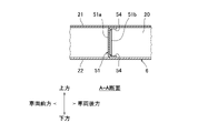
- FIG. 6 is a vertical sectional view showing the shape of the bulkhead 51 according to the second embodiment.
- FIG. 7 is a view seen from the rear of the vehicle showing the shape of the bulkhead 51 according to the second embodiment. Note that FIG. 6 is a vertical cross-sectional view of the AA portion shown in FIG. FIG. 7 is a vertical cross-sectional view of the BB portion shown in FIG.
- the shapes of the bulkheads 50 and 51 are different from those of the first embodiment.
- the bulkhead 51 on the front side of the vehicle is a plate-shaped member formed by being divided in the vehicle width direction according to the divided frame members 19 and 20. That is, the bulkhead 51 includes an inner bulkhead member 51a (first bulkhead member) fixed to the inner frame member 19 in the vehicle width direction and an outer bulkhead member fixed to the outer frame member 20 in the vehicle width direction. It has a two-divided structure composed of 51b (second bulkhead member).
- the inner bulkhead member 51a is arranged inside the frame member 19 arranged on the connecting side of the cross member 10 among the two frame members 19 and 20, and the three sides abut against the inner wall surface of the frame member 19 by welding. It is fixed.
- the outer bulkhead member 51b is arranged inside the frame member 20 arranged on the side opposite to the connecting side of the cross member 10 among the two frame members 19 and 20, and the three sides hit the inner wall surface of the frame member 20. It is in contact and fixed by welding.
- the inner bulkhead member 51a and the outer bulkhead member 51b are partially overlapped to form an overlapping portion 53, and are connected to each other by welding at the overlapping portion 53.
- the bulkhead 50 on the rear side of the vehicle is also a plate-shaped member formed by being divided in the vehicle width direction according to the divided frame members 19 and 20. That is, the bulkhead 50 is configured by connecting the inner bulkhead member 50a and the outer bulkhead member 50b.
- the inner bulkhead member 51a of the bulkhead 51 on the front side of the vehicle is provided with flange portions 54, 54 formed by bending the upper end portion and the lower end portion of the plate-shaped member toward the rear side of the vehicle toward the shackle 12, respectively.
- the flange portions 54, 54 and the upper wall 21 and the lower wall 22 of the side frame 6 are fixed by being overlapped with each other and welded.
- the outer bulkhead member 51b of the bulkhead 51 on the front side of the vehicle is not provided with a flange portion 54 because the upper end portion and the lower end portion are not bent, and the upper end portion and the lower end portion are the upper wall 21 of the side frame 6 and the lower end portion. It is fixed to the inner wall surface of the lower wall 22 by butt welding.
- the bulkheads 50 and 51 have a structure divided in the vehicle width direction, similarly to the side frame 6 having a structure divided in the vehicle width direction. Therefore, before the frame members 19 and 20 are butt-welded to form the side frame 6, the inner bulkhead members 50a and 51a and the outer bulkhead members 50b and 51b are previously fixed to the frame members 19 and 20 by welding, respectively. Can be done. Then, when the frame members 19 and 20 are butt-welded, for example, the overlapping portion 53 of the inner bulkhead members 50a and 51a and the outer bulkhead members 50b and 51b is welded from the holes provided in the frame members 19 and 20. Therefore, the bulkheads 50 and 51 can be easily installed.
- the frame member 19 inside the vehicle width direction to which the cross member 10 is connected suppresses the twist of the side frame 6 by the cross member 10, so that the frame member 19 is outside in the vehicle width direction.
- the stress is higher than that of the frame member 20 of the above, and durability is strongly required.
- the bulkhead 51 on the front side of the vehicle is also strongly required to have durability against the load from the shackle 12. Therefore, by providing the flange portion 54 on the inner bulkhead member 51a of the bulkhead 51 on the front side of the vehicle, the upper wall 21 and the lower wall 22 of the side frame 6 can be firmly supported and fixed, and the bulkhead can be firmly supported and fixed. The durability of the 51 and the side frame 6 can be effectively improved.
- the present invention is not limited to the above embodiment.
- the flange portion 54 is provided only on the inner bulkhead member 51a of the bulkhead 51 on the front side of the vehicle, but the flange portion 54 is provided on the other bulkhead members 51b, 50a, 50b. May be good. Further, the flange portions 54 may be provided on the bulkheads 50 and 51 of the first embodiment.
- one of the bulkhead 51 on the front side of the vehicle and the bulkhead 50 on the rear side of the vehicle may have a divided structure as in the second embodiment.
Abstract
Priority Applications (1)
| Application Number | Priority Date | Filing Date | Title |
|---|---|---|---|
| JP2022563582A JP7332061B2 (ja) | 2020-11-20 | 2021-08-25 | 車両のフレーム構造 |
Applications Claiming Priority (2)
| Application Number | Priority Date | Filing Date | Title |
|---|---|---|---|
| JP2020-193313 | 2020-11-20 | ||
| JP2020193313 | 2020-11-20 |
Publications (1)
| Publication Number | Publication Date |
|---|---|
| WO2022107410A1 true WO2022107410A1 (fr) | 2022-05-27 |
Family
ID=81708659
Family Applications (1)
| Application Number | Title | Priority Date | Filing Date |
|---|---|---|---|
| PCT/JP2021/031205 WO2022107410A1 (fr) | 2020-11-20 | 2021-08-25 | Structure de châssis de véhicule |
Country Status (2)
| Country | Link |
|---|---|
| JP (1) | JP7332061B2 (fr) |
| WO (1) | WO2022107410A1 (fr) |
Citations (3)
| Publication number | Priority date | Publication date | Assignee | Title |
|---|---|---|---|---|
| JPS6316278U (fr) * | 1986-07-18 | 1988-02-03 | ||
| JP2001055163A (ja) * | 1999-08-19 | 2001-02-27 | Toyota Auto Body Co Ltd | 車体構造 |
| JP2006219004A (ja) * | 2005-02-10 | 2006-08-24 | Honda Motor Co Ltd | 車両の車体後部構造 |
Family Cites Families (1)
| Publication number | Priority date | Publication date | Assignee | Title |
|---|---|---|---|---|
| DE102012103015B4 (de) | 2012-04-05 | 2013-12-05 | Pilz Gmbh & Co. Kg | Sicherheitsschaltvorrichtung mit Schaltelement im Hilfskontaktstrompfad |
-
2021
- 2021-08-25 JP JP2022563582A patent/JP7332061B2/ja active Active
- 2021-08-25 WO PCT/JP2021/031205 patent/WO2022107410A1/fr active Application Filing
Patent Citations (3)
| Publication number | Priority date | Publication date | Assignee | Title |
|---|---|---|---|---|
| JPS6316278U (fr) * | 1986-07-18 | 1988-02-03 | ||
| JP2001055163A (ja) * | 1999-08-19 | 2001-02-27 | Toyota Auto Body Co Ltd | 車体構造 |
| JP2006219004A (ja) * | 2005-02-10 | 2006-08-24 | Honda Motor Co Ltd | 車両の車体後部構造 |
Also Published As
| Publication number | Publication date |
|---|---|
| JPWO2022107410A1 (fr) | 2022-05-27 |
| JP7332061B2 (ja) | 2023-08-23 |
Similar Documents
| Publication | Publication Date | Title |
|---|---|---|
| JP5273730B2 (ja) | サスペンション用サブフレーム | |
| JP4774976B2 (ja) | 車両の後部車体構造 | |
| US6120060A (en) | Rear suspension support assembly | |
| KR100253881B1 (ko) | 서스펜션 프레임 브래킷 | |
| JP5637478B2 (ja) | 車両の前部構造 | |
| WO2015029550A1 (fr) | Structure de montage de suspension arrière pour véhicule | |
| JP2015128982A (ja) | 車体後部構造 | |
| KR20210153446A (ko) | 차량용 서브프레임 장치 | |
| JP6052512B2 (ja) | 自動車のリヤサブフレーム構造 | |
| JP5419264B2 (ja) | 車両の前下部構造 | |
| US11225288B2 (en) | Front vehicle body structure of vehicle | |
| WO2022107410A1 (fr) | Structure de châssis de véhicule | |
| JP6802297B2 (ja) | シャーシアセンブリ及び陸上車両 | |
| JP6327303B2 (ja) | 車両の下部車体構造 | |
| WO2023181249A1 (fr) | Structure inférieure de véhicule | |
| KR100280940B1 (ko) | 자동차의 차체 하부 보강구조 | |
| WO2023181248A1 (fr) | Structure de châssis de véhicule | |
| JP2001294172A (ja) | サスペンションフレーム構造 | |
| WO2022107533A1 (fr) | Structure de fixation de boîte de chargement de véhicule | |
| JP2020157983A (ja) | 車両のサイドメンバ構造 | |
| JPH08169360A (ja) | 車両用サブフレーム構造 | |
| JPH06278642A (ja) | サスペンション用サブフレーム | |
| US20230311993A1 (en) | Subframe | |
| KR102377398B1 (ko) | 초소형 전기자동차의 공용플렛폼 | |
| JP4908391B2 (ja) | 運搬車におけるリヤフェンダ支持構造 |
Legal Events
| Date | Code | Title | Description |
|---|---|---|---|
| 121 | Ep: the epo has been informed by wipo that ep was designated in this application |
Ref document number: 21894285 Country of ref document: EP Kind code of ref document: A1 |
|
| DPE2 | Request for preliminary examination filed before expiration of 19th month from priority date (pct application filed from 20040101) | ||
| ENP | Entry into the national phase |
Ref document number: 2022563582 Country of ref document: JP Kind code of ref document: A |
|
| REG | Reference to national code |
Ref country code: BR Ref legal event code: B01A Ref document number: 112023009632 Country of ref document: BR |
|
| NENP | Non-entry into the national phase |
Ref country code: DE |
|
| ENP | Entry into the national phase |
Ref document number: 112023009632 Country of ref document: BR Kind code of ref document: A2 Effective date: 20230518 |
|
| 122 | Ep: pct application non-entry in european phase |
Ref document number: 21894285 Country of ref document: EP Kind code of ref document: A1 |