EP1077101A2 - Méthode et appareil pour le contrôle d'un cordon de soudure à l'arc - Google Patents
Méthode et appareil pour le contrôle d'un cordon de soudure à l'arc Download PDFInfo
- Publication number
- EP1077101A2 EP1077101A2 EP00306377A EP00306377A EP1077101A2 EP 1077101 A2 EP1077101 A2 EP 1077101A2 EP 00306377 A EP00306377 A EP 00306377A EP 00306377 A EP00306377 A EP 00306377A EP 1077101 A2 EP1077101 A2 EP 1077101A2
- Authority
- EP
- European Patent Office
- Prior art keywords
- welding
- current waveform
- excursion
- positional
- short
- Prior art date
- Legal status (The legal status is an assumption and is not a legal conclusion. Google has not performed a legal analysis and makes no representation as to the accuracy of the status listed.)
- Granted
Links
Images

Classifications
-
- B—PERFORMING OPERATIONS; TRANSPORTING
- B23—MACHINE TOOLS; METAL-WORKING NOT OTHERWISE PROVIDED FOR
- B23K—SOLDERING OR UNSOLDERING; WELDING; CLADDING OR PLATING BY SOLDERING OR WELDING; CUTTING BY APPLYING HEAT LOCALLY, e.g. FLAME CUTTING; WORKING BY LASER BEAM
- B23K9/00—Arc welding or cutting
- B23K9/02—Seam welding; Backing means; Inserts
- B23K9/0216—Seam profiling, e.g. weaving, multilayer
-
- B—PERFORMING OPERATIONS; TRANSPORTING
- B23—MACHINE TOOLS; METAL-WORKING NOT OTHERWISE PROVIDED FOR
- B23K—SOLDERING OR UNSOLDERING; WELDING; CLADDING OR PLATING BY SOLDERING OR WELDING; CUTTING BY APPLYING HEAT LOCALLY, e.g. FLAME CUTTING; WORKING BY LASER BEAM
- B23K9/00—Arc welding or cutting
- B23K9/12—Automatic feeding or moving of electrodes or work for spot or seam welding or cutting
- B23K9/127—Means for tracking lines during arc welding or cutting
- B23K9/1272—Geometry oriented, e.g. beam optical trading
- B23K9/1276—Using non-contact, electric or magnetic means, e.g. inductive means
Definitions
- the present invention relates to a tracking monitoring device for determining the state of how a weld line is tracked under arc sensing control to let the oscillating center of a welding torch track a correct weld line along the groove center based on a welding current waveform when the welding torch is oscillated in the direction of the groove width, and a tracking control device using the monitoring technique.
- an arc sensing control is generally used as a method of controlling a welding torch to track a weld line.
- the arc sensing control based on change in the welding current associated with change in the wire extension length when the welding torch is oscillated in the direction of the groove width, the positional correction (moving the center of oscillation in the horizontal and vertical directions) is made in the groove width direction of the welding torch (hereinafter referred to as "the oscillating direction") and the groove vertical direction (hereinafter referred to as "the direction of the torch axis ").
- the arc phenomenon is very unstable and proceeds at an ultra high speed, and therefore the reliability of the present arc sensing control is limited.
- an objective methodology to determine the quality of welding has not been developed yet, and defectively welded products could be unexpectedly marketed at any time. Since the reliability of the present arc sensing control is low and in the fields requiring high quality of arc welding such as high speed welding for a thin steel plate, more complicated and expensive active control systems other than the arc sensing control such as providing a laser displacement sensor at the top of a welding torch for example is inevitable.
- the magnitudes of the integrated value of welding current at prescribed intervals obtained at both ends of weaving (oscillation) are compared each other mainly for adjusting displacement in the groove width direction.
- the welding torch has then its weaving center position corrected in the transverse direction based on the comparison signal and is made to track the correct weld line.
- the integrated value of welding current at both ends of weaving must be averaged several times in order to improve the positional detection accuracy, the output of the positional excursion correction signal is delayed by a time period corresponding to the number of averaging, and the tracking control accuracy of the welding torch is degraded. If the welding speed is slowed to shorten the weld line proceeding during this wasteful time, the tracking control accuracy certainly improves and yet the production efficiency is downed instead.
- the weaving frequency may be increased. If however the weaving frequency is increased, the weaving frequency is reduced, integrating and averaging the welding current including much disturbance information does not improve the removal ratio of the disturbance information. If the number of averaging is increased, the adverse effect of the disturbance information upon the correction signal may be reduced, but the output of the positional excursion correction signal is delayed for the increase in the number of averaging which would eventually prevent the tracking control accuracy from improving.
- the method proposed by Japanese Patent Publication No. Hei 2-4396 is directed to correction of positional excursion from a weld line in weaving welding process. More specifically, there are provided a comparator to identify whether it is in a short-circuit period or in an arc period based on a welding voltage signal for the arc period, a selecting circuit to extract a welding current signal in the process of arc duration by a signal identifying arc duration from the comparator, an integrator to integrate the output signal of the selecting circuit for one cycle or half the cycle of weaving, a counter to count arc period, an average value calculation circuit to output an average value signal produced by averaging the outputs of the integrator by the arc period, and a hold circuit to hold the average value signal at the end of one cycle or half the cycle of weaving.
- the output of the hold circuit and a set value for welding current are compared to determine a positional excursion in the vertical direction, i.e., the direction of the welding torch axis. Furthermore, a positional excursion in the horizontal direction, i.e., the direction perpendicular to the direction of the welding torch axis is further determined based on the polarity of the output of the hold circuit. A positional excursion correction instruction is then output to a correction motor.
- the welding current at both ends of weaving is detected and compared to a prescribed reference value to obtain a signal for positional excursion correction from the weld line.
- the detected welding current contains much disturbance information other than the positional information, and the position detection accuracy can be extremely low in a low current state such as in a short-circuiting transfer state and a globular transfer state.
- the method is therefore only limitatively applicable in a high current, spray transfer state.
- the tracking monitoring device for a weld line includes:
- the sampling means includes folding and superposing means for sampling a linearly interpolated welding current waveform at a plurality of intervals corresponding to one cycle of oscillation of the welding torch, and folding and superposing the sampled welding current waveforms at a position corresponding to half the cycle of oscillation.
- a height at a fixed point corresponding to the central position of the approximated straight line in other words, a point corresponding to a position of one fourth (90°) to three fourths (270°) of the cycle of the oscillation of the welding torch and a predetermined set value for welding current may be compared to display the difference as the positional excursion direction and positional excursion distance of the welding torch in the direction of the welding torch axis.
- the position at the fixed point might have to be set other than at a position corresponding to one fourth to three fourths of the cycle of oscillation.
- the welding current waveform When the welding current waveform is replaced by an approximated straight line by the replacing means, the welding current waveform may be previously converted into a smoothed current waveform using average means according to a moving-average method.
- indented waves in the welding current waveform created by sputtering or the like can be eliminated, and disturbance information other than the positional information of the welding torch can be removed as much as possible.
- by setting the waveform sampling cycle to be relatively long at the time of replacement to the approximated straight line sufficient tracking control accuracy in practice can be maintained as the operation speed is to be further increased.
- the short-circuiting current waveform removing means includes threshold value setting means for setting a reference welding voltage to differentiate an arc period and a short-circuit period in a welding voltage waveform as a threshold value.
- threshold value setting means for setting a reference welding voltage to differentiate an arc period and a short-circuit period in a welding voltage waveform as a threshold value.
- a waveform portion to be cancelled as a short-circuit period is extended backward and forward by the first operation means and the second operation means, and the welding current waveform including the part immediately before the start of a short- circuit period and the part immediately after the start of an arc period is canceled.
- the influence of the short- circuit period as a large disturbance factor can be substantially completely removed in monitoring the tracking of the welding torch.
- the tracking control device for a weld line includes:
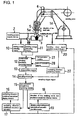
- Fig. 1 is a schematic block diagram of a tracking control device including a tracking monitoring device for a weld line according to one embodiment of the present invention.
- the device When there is no feedback from oscillating direction positional excursion operation means 17 and the direction of the welding torch axis positional excursion operation means 19 to a welding robot torch position control device 20, the device functions as a simple tracking determining device.
- the reference numeral 1 designates a consumable electrode gas shielded arc welding device (hereinafter simply as the "arc welding device") including a welding robot 1a, 2 a welding power supply device, 3 a base metal having a groove welding portion, and 4 a welding wire serving as a welding electrode.
- arc welding device a consumable electrode gas shielded arc welding device
- the supply side of the welding wire 4 is wound into a coil, and the contact tip end of the welding wire 4 let out at a prescribed speed from the supply side of the coil through a feed roller 6 is supplied toward the base metal 3 as it is held by a contact tip 5a of the welding torch 5.
- Reference numeral 10 represents welding current detecting means
- 11 represents welding voltage detecting means. These detecting means 10 and 11 detect welding current and welding voltage supplied from the welding power supply device 2 to the base metal 3 and the welding wire 4, respectively.
- Fig. 1 there are also short-circuiting current waveform removing means 12, interpolation means 13, sampling means 14, approximated straight line replacing means 15, oscillating direction positional excursion display means 16, oscillating direction positional excursion operation means 17, the positional excursion direction of the welding torch axis display means 18, the positional excursion direction of the welding torch axis operation means 19, a welding robot torch position control device 20, and oscillating direction detecting means 22.
- Each block will be further described.
- the welding power supply device 2 is a high speed control type device having its output controlled using an inverter type, and can control the waveforms of the welding current and the welding voltage.
- the welding current detecting means 10 is connected to the base metal 3 to detect the welding current
- the welding voltage detecting means 11 is connected to the welding wire 4 and the base metal 3 to detect the welding voltage.
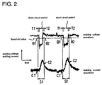
- Fig. 2 shows an example of the welding voltage and current waveforms detected by these detecting means.
- the short-circuiting current waveform removing means 12 removes waveforms S1 and S2 in short-circuit periods from the welding current waveform shown in Fig. 2. More specifically, a reference voltage for differentiating between the arc period and short-circuit period is set in the welding voltage waveform as a threshold value by threshold value setting means. Then, the welding current waveform corresponding to the voltage portion lower than the threshold value is basically removed as a short-circuit period.
- the technique of thus removing the welding current waveform in the short-circuit period has been partly proposed in a conventional technique for example by Japanese Patent Publication No. Hei 2-4396 in connection with the use of a comparator.
- the waveform portions corresponding to the extension portions before and after the current waveform for prescribed time periods T1 and T2 are also removed as a short- circuiting current waveform portion.
- first operation means 27 to perform operation to obtain a position in the welding current waveform corresponding to a point the prescribed time period T1 before the reaching point B1 at which the threshold value in the welding current waveform is reached as a starting point C1 for removing a short-circuiting current waveform (see Fig. 1).
- second operation means 28 to perform operation to obtain a position in the welding current waveform corresponding to a point the prescribed time period T2 after the departing point B2 which departs from the threshold value in the welding voltage waveform as an end point C2 for removing the short- circuiting current waveform (see Fig. 1). More specifically, these first and second operation means 27 and 28 are expressed as time steps in an operation program.
- the welding current waveform between the starting point C1 and the end point C2 for removing the short-circuit waveform is cancelled by the waveform canceling means.
- the waveform canceling means is expressed as a waveform memory clearing step in the operation program.
- the preceding time period T1 and succeeding time period T2 are for example set to 1 msec and 5 msec, respectively. However, the optimum values for the time periods differ depending upon the welding conditions and the level of the threshold value, and the values are set in view of specific conditions.
- the welding current waveform immediately after the start of an arc is generally less stable than that immediately before the start of a short-circuit, and therefore the succeeding time period T2 may be generally set longer than the preceding time period T1.
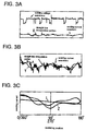
- the interpolation means 13 linearly interpolates a missing part of a waveform generated by the above-described removal of short-circuiting current waveform.
- the starting point C1 and the end point C2 for removing the short-circuiting current waveform in Fig. 2 are connected by a straight line (see the straight line part of the lower side waveform X in Fig. 3A).
- the linear interpolation is performed to improve the operation accuracy in operations to obtain an oscillating direction positional excursion or the direction of the welding torch axis positional excursion distance in the succeeding steps.
- the welding current in a short-circuit period completely disregarded in the conventional technique of extracting only the welding current signal during an arc period by the selecting circuit as disclosed by Japanese Patent Publication No.
- Hei 2-4396 is replaced with a linear welding current waveform free from noises.
- the behavior of actual arc welding is reflected upon the operation of the oscillating direction positional excursion or the direction of the welding torch axis positional excursion as much as possible.
- the moving average and approximated straight line replacement in the succeeding steps can be effective only with this linear interpolation.
- the sampling means 14 samples the linearly interpolated welding current waveform at a plurality of substantially equal intervals corresponding to the oscillating frequency of the welding torch.
- the waveform X in Fig. 3B is sampled at intervals of one cycle of oscillation.
- substantially equal suggests that strictly speaking, the time intervals between oscillation end points are not necessarily fixed.
- the sampling means 14 is controlled by an oscillated synchronizing pulse output representing an oscillating end point in a welding robot system.
- the waveform X in Fig. 3B is converted into the waveform Y in Fig. 3B by moving average employed as averaging means, and then the waveform Y is divided at each cycle of oscillation.
- the divisional parts may be subjected to moving average to obtain divided waveform Y.
- the interval of sampling is conveniently set as one cycle of oscillation in connection with folding and superposing means which will be described later, but the waveform may be sampled for each of half the cycle of oscillation without using the folding and superposing means.
- the sampling timing is applied by a sampling trigger signal from oscillating direction detecting means 22.
- the oscillated synchronizing pulse signal per se may be basically used as the sampling trigger signal. However, if the time delay between the oscillated synchronizing pulse signal and an actual welding torch oscillating end point is relatively large, the time delay is previously detected and the sampling timing of the welding current waveform by the sampling means is preferably set delayed from the oscillated synchronizing pulse signal by the time delay.
- the actual welding torch oscillating end point is measured by a laser displacement sensor attached to the welding torch for example, and the time delay is calculated by simultaneously measuring the oscillated synchronizing pulse signal and the end point by a laser displacement sensor output. Since the time delay is subtly different for each welding robot, each robot is detected for time delay before the welding operation.
- the folding and superposing means folds the waveform for one cycle of oscillation smoothed by moving average at a half-cycle position (180°) for superposing as shown in Fig 3C.
- the folding and superposing means folds the waveform for one cycle of oscillation at the half-cycle position in the center and superposes waveforms each for one cycle of oscillation with one another to make it possible to express the characteristic of the welding current waveform for one cycle of oscillation by the inclination and height of one straight line in the following approximated straight line replacement step. Note that if the welding current waveform is sampled for every half cycle of oscillation as described above, such folding and superposing means is not necessary.
- the going path (to the right) and the return path (to the left) of the curve Z in Fig. 3C are each independently subjected to approximated straight line replacement in the following step.
- the approximated straight line replacing means 15 replaces sampled welding current waveforms by an approximated straight line by a least square method or a method substantially equivalent thereto.
- the welding current waveform for one cycle of oscillation is expressed by the inclination and height of one approximated straight line
- the oscillating direction positional excursion information can be derived from the inclination angle and direction of the approximated straight line.
- the direction of the welding torch axis positional excursion information can be derived from the height of the approximated straight line.
- the approximated straight line is derived from a welding current waveform smoothed by moving average processing according to this embodiment, while the tracking monitoring accuracy and control accuracy are not lowered if the approximated straight line is directly derived from the original current waveform without moving averaging processing.
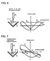
- the oscillating direction positional excursion display means 16 and the torch axis positional excursion display means 18 are typically a CRT screen or a liquid crystal display screen to display images as shown in the left part of Figs. 4 to 9.
- display means to give analog or digital indication of the oscillating direction positional excursion distance and the direction of the welding torch axis positional excursion distance or their changes with time may be employed.
- the images are displayed based on the operation results of the oscillating direction positional excursion operation means 17 and the torch axis positional excursion operation means 19.
- the operation contents of both operation means 17 and 19 will be described as follows by referring to waveforms in the right part of Figs. 4 to 9.
- the waveform in the right part in each figure is formed by folding and superposing a welding current waveform for one cycle of oscillation at a half cycle point and the vertical line corresponds to one fourth to three fourths of the cycle of oscillation.
- the thick horizontal line L in Figs. 4 to 6 and the thick inclined line L in Figs. 7 to 9 are both approximated straight lines L obtained from the waveforms in these figures by the least square method. Note, however, that the waveform itself is created for the convenience sake in view of decrease/increase in the welding current value depending upon the altitude between the welding torch 5 and the base metal 3 rather than a real waveform shown in Fig. 3C.
- the waveform in Fig. 4 represents a normal welding state in which the oscillating direction positional excursion and the direction of the welding torch axis positional excursion are both zero.
- the inclination of the approximated straight line L is zero (level), while the central height of the approximated straight line L is in coincidence with a reference height (set welding current value).
- Fig. 5 shows the state in which there is the direction of the welding torch axis positional excursion slightly downward from the correct welding state in Fig. 4.
- the welding current increases in inverse proportion to decrease in the altitude between the welding torch 5 and the base metal 3, so that the approximated straight line L moves upward still with the inclination of zero.
- Fig. 6 shows the state in which there is the direction of the welding torch axis positional excursion slightly upward from the normal welding state in Fig. 4.
- the welding current decreases in inverse proportion to increase in the altitude between the welding torch 5 and the base metal 3, and therefore the approximated straight line L moves downward still with the inclination of zero.
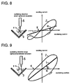
- Fig. 7 shows the state in which there is an oscillating direction positional excursion slightly leftward from the groove center.
- the altitude between the welding torch 5 and the base material 3 decreases on the left side of the oscillation center, the waveform Z becomes dissymmetry with greater current on the left side and therefore the approximated straight line L inclines in the upper left direction.
- Fig. 8 shows the state in which there is an oscillating direction positional excursion slightly rightward from the groove center.
- the waveform Z becomes dissymmetry with greater current on the right side and the approximated straight line inclines in the upper right direction.
- the oscillating direction positional excursion operation means 17 and the direction of the welding torch axis positional excursion operation means 19 perform operation to obtain the oscillating direction positional excursion amount ⁇ h and the direction of the welding torch axis positional excursion ⁇ v based on the inclination angle of the approximated straight line and the height corresponding to one fourth to three fourths of the cycle of oscillation as described above.
- the oscillating direction detecting means 22 basically uses a synchronizing pulse signal for oscillating direction instruction from the welding robot torch position control device 20 as it is. However, there exists a subtle response delay characteristic in practice between the synchronizing pulse signal described above and the operation of the welding robot.
- a displacement sensor is provisionally provided at the top of the welding torch 5, actual time delay after the rising of a synchronizing pulse signal for oscillating direction instruction until the detection of the oscillating end point by the displacement sensor is actually measured. Then, a separate pulse signal delayed for this time delay from the synchronizing pulse signal for oscillating direction instruction is used as a sampling trigger signal for the sampling means 14.
- the sampling trigger signal provides a sampling timing for sampling a welding current waveform corresponding to the oscillating frequency by the sampling means 14 described above. Sampling is started when the n-th synchronizing pulse (ON) is detected using the synchronizing pulse signal of the oscillating direction detection means 22 as a reference, while the sampling for the next one cycle is completed when the n+1-th synchronizing pulse signal (ON) is detected, and the sampling for the next cycle is started at a time. Note that when the synchronizing pulse signal attains an ON state, the welding torch 5 starts an oscillating stroke from one end to the other end. When the synchronizing pulse signal attains an OFF state, the welding torch 5 starts an oscillating stroke in the opposite direction, i.e., from the other end to the one end.
- the operation of the tracking control device will be now described.
- basic conditions such as the oscillating frequency, the oscillating width, the position of the welding torch height are input to the welding robot torch position control device 20 of the welding robot 1a.
- the welding robot 1a starts welding in response to a received start signal, and performs arc welding while the welding torch 5 aims at a plurality of prescribed taught points provided along the groove weld line of the base metal 3.
- the welding robot torch position control device 20 controls the torch position of the welding robot 1a so that the oscillating center of welding torch 5 tracks the weld line. More specifically, as long as the weld line is correctly tracked by appropriate welding current, the horizontal approximated straight line at an appropriate height is displayed as shown in Fig. 4. If however the welding torch 5 is shifted in the direction of the welding torch axis for example, a position in the approximated straight line corresponding to one fourth to three fourths of the cycle of oscillating positional excursions upward and downward as shown in Figs. 5 and 6.
- a signal from the direction of the welding torch axis positional excursion operation means 19 is input to the welding robot torch position control device 20. More specifically, in the welding robot torch position control device 20, if the current value of the approximated straight line at a position corresponding to one fourth to three fourths of the cycle of oscillation (the height of the approximated straight line L at the central position in Figs. 4 to 9) is higher than the initially set current value, the welding torch is controlled to be raised so that the difference therebetween can be reduced. Conversely, if the welding current value is lower than the initially set value for welding current, the welding torch is controlled to be lowered.
- the oscillating center is shifted from the weld line in the horizontal direction, as shown in Figs. 7 to 9, the approximated straight line inclines in the upper left or upper right direction.
- a signal from the oscillating direction positional excursion operation means 17 is input to the welding robot torch position control device 20.
- the direction of the welding torch axis control and the oscillating direction control are combined.
- the welding torch 5 is moved in the vertical and horizontal directions by the welding robot 1a, the oscillating center of the welding wire 4 is controlled to track the weld line, and the welding current is controlled to take a prescribed value.
- a correction instruction is issued to the welding robot torch position control device 20 in order to nullify the positional excursion.
- the position of the welding torch 5 (the position of oscillating center and the welding torch height) is corrected.
- a correction instruction is output to the welding robot torch position control device 20 based on the operation values of the oscillating direction positional excursion operation means 17 and the direction of the welding torch axis positional excursion operation means 19.
- the output values and the corrected operation values of the operation means 17 and 19 are held and accumulated. If their relative relation is learned by artificial intelligence, an optimum correction instruction value may be instantaneously output thereafter in other applications.
- the present invention may be subjected to various modifications other than this embodiment.
- the moving average method is employed in this embodiment in order to allow the welding current to have a smoothed waveform
- methods other than the moving average or a method substantially identical to the moving average to smooth a waveform may be employed.
- the approximated straight line is obtained according to the least square method in this embodiment, a similar approximated straight line may be obtained according to a method substantially identical method to the least square method.
- the tracking monitoring device may be implemented in an embodiment without the direction of the welding torch axis positional excursion display means other than the embodiment in which the oscillating direction positional excursion display means and the direction of the welding torch axis positional excursion display means are both provided.
- the oscillating direction positional excursion distance and the direction of the welding torch axis positional excursion distance for each cycle of oscillation of the welding torch are available based on the inclination angle and height of the approximated straight line substantially in real time. Therefore, as compared to the conventional tracking monitor or tracking control by averaging the integrated values of the welding current waveforms, there is very small time delay in the arc sensing control. Thus the tracking monitoring accuracy or the welding torch tracking control accuracy can be significantly improved in proportion to the oscillating frequency. Therefore, in the tracking monitoring device, the degree of the tracking positional excursion can be accurately monitored in real time, so that products defective in welding quality because of the tracking positional excursion can be surely prevented from being marketed. Furthermore, in the tracking control device, the tracking positional excursion can be instantaneously corrected and the manufacture of products defective in the welding quality per se can be prevented.
- the first and second operation means can remove the welding current including disturbance information including a portion immediately before the start of a short-circuit period and a portion immediately after the start of an arc period. Furthermore, the welding current in unstable welding such as in arc discontinuity can be removed, so that the disturbance information except for the welding torch positional information generated in the welding current detection can be removed as much as possible. Thus, without dependence upon the welding conditions, the arc positional excursion from the weld line can be detected with high accuracy. The welding quality can be improved and the man-hours involved in correction after the welding can be reduced.
- the aiming angle of the welding torch changes under the arc sensing control, high accuracy tracking control for a weld line is enabled, and the man-hours necessary for the operation of teaching the welding robot can be reduced accordingly.
- Some variations in the precision of parts or variations in connection with jigs do not affect the control of the welding torch at all. Therefore, the yield can be improved by lowering the part precision management standard and jigs can be simplified to reduce the cost.
- the conventional, well-known groove tracking device is not necessary.
- Various sensors which could be an obstacle in the way of welding is not attached to the welding torch, so that the flexibility of the working position can be improved, and high reliability can be provided in bad environments in association with sputtering, fume, arc heat or the like. As a result, the detection accuracy and durability can be prevented from being lowered.
Landscapes
- Engineering & Computer Science (AREA)
- Physics & Mathematics (AREA)
- Plasma & Fusion (AREA)
- Mechanical Engineering (AREA)
- Geometry (AREA)
- Butt Welding And Welding Of Specific Article (AREA)
- Arc Welding Control (AREA)
- Arc Welding In General (AREA)
Applications Claiming Priority (2)
| Application Number | Priority Date | Filing Date | Title |
|---|---|---|---|
| JP23088199 | 1999-08-17 | ||
| JP23088199A JP3746922B2 (ja) | 1999-08-17 | 1999-08-17 | 溶接線の倣い判定装置と倣い制御装置 |
Publications (4)
| Publication Number | Publication Date |
|---|---|
| EP1077101A2 true EP1077101A2 (fr) | 2001-02-21 |
| EP1077101A8 EP1077101A8 (fr) | 2001-05-16 |
| EP1077101A3 EP1077101A3 (fr) | 2003-03-26 |
| EP1077101B1 EP1077101B1 (fr) | 2008-02-06 |
Family
ID=16914778
Family Applications (1)
| Application Number | Title | Priority Date | Filing Date |
|---|---|---|---|
| EP00306377A Expired - Lifetime EP1077101B1 (fr) | 1999-08-17 | 2000-07-26 | Méthode et appareil pour le contrôle d'un cordon de soudure à l'arc |
Country Status (4)
| Country | Link |
|---|---|
| US (1) | US6429404B1 (fr) |
| EP (1) | EP1077101B1 (fr) |
| JP (1) | JP3746922B2 (fr) |
| DE (1) | DE60037953T2 (fr) |
Cited By (2)
| Publication number | Priority date | Publication date | Assignee | Title |
|---|---|---|---|---|
| CN102922094A (zh) * | 2012-10-09 | 2013-02-13 | 上海工程技术大学 | 一种基于热输入的超小尺度焊缝跟踪方法 |
| CN109848524A (zh) * | 2019-02-02 | 2019-06-07 | 浙江师范大学 | 窄间隙熔化极气体保护立焊焊缝跟踪方法 |
Families Citing this family (24)
| Publication number | Priority date | Publication date | Assignee | Title |
|---|---|---|---|---|
| JP4854860B2 (ja) * | 2001-02-19 | 2012-01-18 | 中央精機株式会社 | 溶接線の倣い判定装置と倣い制御装置 |
| US6751843B2 (en) * | 2001-03-09 | 2004-06-22 | Applied Kinetics, Inc. | Method for improved static attitude of head suspension assemblies with electrical interconnects |
| JP4515018B2 (ja) * | 2002-08-26 | 2010-07-28 | 株式会社ダイヘン | パルスアーク溶接の倣い制御方法 |
| SE525419C2 (sv) * | 2003-06-13 | 2005-02-15 | Abb Ab | Metod för avstämning av ett system för bågsvetsning samt bågsvetssystem, datorprogramprodukt och datorläsbart medium |
| FR2896716B1 (fr) * | 2006-01-31 | 2009-06-26 | Abb Mc Soc Par Actions Simplif | Procede de pilotage d'une station de travail robotisee et station de travail robotisee correspondante |
| US8927901B2 (en) * | 2008-03-17 | 2015-01-06 | Alcoa Inc. | Buried-arc welding of metal work pieces with through-the-arc seam tracking |
| US8310324B2 (en) * | 2008-04-11 | 2012-11-13 | Will Harris | Releasable guide and methods for using same |
| WO2010116695A1 (fr) * | 2009-04-08 | 2010-10-14 | パナソニック株式会社 | Procédé de soudage à l'arc et appareil de soudage à l'arc |
| US10058947B2 (en) * | 2009-11-25 | 2018-08-28 | Panasonic Intellectual Property Management Co., Ltd. | Welding method and welding device |
| KR101473639B1 (ko) * | 2013-02-25 | 2014-12-17 | 대우조선해양 주식회사 | 수평 맞대기 이음 대용착 용접 장치 및 그 방법 |
| US10052759B2 (en) * | 2013-03-29 | 2018-08-21 | Fanuc America Corporation | Adaptive control of robotic laser braze/weld operation |
| CN103438908B (zh) * | 2013-09-11 | 2015-07-22 | 哈尔滨工业大学 | 差动变压传感器的次级信号处理电路 |
| US9962785B2 (en) * | 2013-12-12 | 2018-05-08 | Lincoln Global, Inc. | System and method for true electrode speed |
| JP2017506583A (ja) * | 2014-02-11 | 2017-03-09 | マグナ インターナショナル インコーポレイテッド | 異種材料の接合方法 |
| CN104874946B (zh) * | 2015-04-30 | 2017-11-10 | 芜湖林一电子科技有限公司 | 一种机器视觉跟踪焊缝系统 |
| EP3165314A1 (fr) * | 2015-11-06 | 2017-05-10 | Siegfried Plasch | Procede de rechargement par soudure |
| JP6367985B2 (ja) * | 2017-01-26 | 2018-08-01 | ファナック株式会社 | アークセンサ調整装置、及びアークセンサ調整方法 |
| JP6496340B2 (ja) * | 2017-03-17 | 2019-04-03 | ファナック株式会社 | スキャナ制御装置、ロボット制御装置及びリモートレーザ溶接ロボットシステム |
| US11897060B2 (en) * | 2017-11-29 | 2024-02-13 | Lincoln Global, Inc. | Systems and methods for welding torch weaving |
| US11065707B2 (en) * | 2017-11-29 | 2021-07-20 | Lincoln Global, Inc. | Systems and methods supporting predictive and preventative maintenance |
| JP7369981B2 (ja) * | 2019-06-28 | 2023-10-27 | パナソニックIpマネジメント株式会社 | リペア溶接システム、リペア溶接方法、検査装置およびロボット制御装置 |
| CN111843115B (zh) * | 2020-06-19 | 2022-04-12 | 渤海造船厂集团有限公司 | 一种弧焊机器人用可调节同步触发焊接电流控制方法 |
| US11407110B2 (en) * | 2020-07-17 | 2022-08-09 | Path Robotics, Inc. | Real time feedback and dynamic adjustment for welding robots |
| CN117428302B (zh) * | 2023-12-20 | 2024-02-20 | 苏芯物联技术(南京)有限公司 | 一种焊接管道供气流速智能动态控制方法及系统 |
Citations (3)
| Publication number | Priority date | Publication date | Assignee | Title |
|---|---|---|---|---|
| JPS6056483A (ja) * | 1983-09-09 | 1985-04-02 | Yaskawa Electric Mfg Co Ltd | 溶接線追従装置 |
| US4587398A (en) * | 1983-08-26 | 1986-05-06 | Hitachi Ltd. | Weld line system and method for control |
| US5130514A (en) * | 1989-05-10 | 1992-07-14 | Daihen Corporation | Control apparatus for tracing a weld line in a welding apparatus and control method therefor |
Family Cites Families (3)
| Publication number | Priority date | Publication date | Assignee | Title |
|---|---|---|---|---|
| US4151395A (en) * | 1976-07-06 | 1979-04-24 | CRC-Crose, International, Inc. | Method and apparatus for electric arc and analogous welding under precision control |
| JPH0630809B2 (ja) * | 1986-12-27 | 1994-04-27 | フアナツク株式会社 | 自動ア−ク溶接機の制御装置 |
| JPH0647172B2 (ja) * | 1987-01-23 | 1994-06-22 | ファナック株式会社 | 自動溶接装置 |
-
1999
- 1999-08-17 JP JP23088199A patent/JP3746922B2/ja not_active Expired - Fee Related
-
2000
- 2000-07-26 DE DE60037953T patent/DE60037953T2/de not_active Expired - Fee Related
- 2000-07-26 US US09/625,668 patent/US6429404B1/en not_active Expired - Fee Related
- 2000-07-26 EP EP00306377A patent/EP1077101B1/fr not_active Expired - Lifetime
Patent Citations (3)
| Publication number | Priority date | Publication date | Assignee | Title |
|---|---|---|---|---|
| US4587398A (en) * | 1983-08-26 | 1986-05-06 | Hitachi Ltd. | Weld line system and method for control |
| JPS6056483A (ja) * | 1983-09-09 | 1985-04-02 | Yaskawa Electric Mfg Co Ltd | 溶接線追従装置 |
| US5130514A (en) * | 1989-05-10 | 1992-07-14 | Daihen Corporation | Control apparatus for tracing a weld line in a welding apparatus and control method therefor |
Non-Patent Citations (3)
| Title |
|---|
| OHSHIMA K ET AL: "Controlling of torch attitude and seam tracking using neuro arc sensor" INDUSTRIAL ELECTRONICS, CONTROL, AND INSTRUMENTATION, 1995., PROCEEDINGS OF THE 1995 IEEE IECON 21ST INTERNATIONAL CONFERENCE ON ORLANDO, FL, USA 6-10 NOV. 1995, NEW YORK, NY, USA,IEEE, US, 6 November 1995 (1995-11-06), pages 1185-1189, XP010154891 ISBN: 0-7803-3026-9 * |
| OHSHIMA K ET AL: "Sensor fusion using neural network in the robotic welding" INDUSTRY APPLICATIONS CONFERENCE, 1995. THIRTIETH IAS ANNUAL MEETING, IAS '95., CONFERENCE RECORD OF THE 1995 IEEE ORLANDO, FL, USA 8-12 OCT. 1995, NEW YORK, NY, USA,IEEE, US, 8 October 1995 (1995-10-08), pages 1764-1769, XP010193218 ISBN: 0-7803-3008-0 * |
| PATENT ABSTRACTS OF JAPAN vol. 009, no. 191 (M-402), 7 August 1985 (1985-08-07) & JP 60 056483 A (YASKAWA DENKI SEISAKUSHO KK), 2 April 1985 (1985-04-02) * |
Cited By (3)
| Publication number | Priority date | Publication date | Assignee | Title |
|---|---|---|---|---|
| CN102922094A (zh) * | 2012-10-09 | 2013-02-13 | 上海工程技术大学 | 一种基于热输入的超小尺度焊缝跟踪方法 |
| CN109848524A (zh) * | 2019-02-02 | 2019-06-07 | 浙江师范大学 | 窄间隙熔化极气体保护立焊焊缝跟踪方法 |
| CN109848524B (zh) * | 2019-02-02 | 2020-12-01 | 浙江师范大学 | 窄间隙熔化极气体保护立焊焊缝跟踪方法 |
Also Published As
| Publication number | Publication date |
|---|---|
| EP1077101A3 (fr) | 2003-03-26 |
| EP1077101B1 (fr) | 2008-02-06 |
| DE60037953T2 (de) | 2009-05-20 |
| JP3746922B2 (ja) | 2006-02-22 |
| JP2001047240A (ja) | 2001-02-20 |
| DE60037953D1 (de) | 2008-03-20 |
| US6429404B1 (en) | 2002-08-06 |
| EP1077101A8 (fr) | 2001-05-16 |
Similar Documents
| Publication | Publication Date | Title |
|---|---|---|
| US6429404B1 (en) | Method and apparatus for determining seam tracking control of arc welding | |
| US4151395A (en) | Method and apparatus for electric arc and analogous welding under precision control | |
| US4417126A (en) | Method of controlling a weaving path of a welding torch in arc welding with a consumable electrode | |
| JP6720452B2 (ja) | アーク倣い溶接方法 | |
| CN114619123B (zh) | 一种窄间隙焊接方法、装置及系统 | |
| JP4854860B2 (ja) | 溶接線の倣い判定装置と倣い制御装置 | |
| CN114682917B (zh) | 一种单道多层埋弧焊激光-磁控电弧复合式焊缝跟踪方法 | |
| EP0392961B1 (fr) | Alignement pour ligne d'assemblage entre parties accouplées | |
| JP2001208523A (ja) | 溶接ビード形状の検出方法および装置 | |
| JPS63192562A (ja) | 溶接倣い制御方法及び溶接倣い制御装置 | |
| JP3463142B2 (ja) | 溶接装置 | |
| JP3608060B2 (ja) | 溶接線倣い制御方法および装置 | |
| JP2504056B2 (ja) | 電縫管溶接の入熱制御方法およびその装置 | |
| Luo et al. | Laser visual sensing and process control in robotic arc welding of titanium alloys | |
| Lanzetta et al. | On-line control of robotized gas metal arc welding | |
| CN114043081B (zh) | 一种激光焊接的多焊缝类型特征点识别方法及系统 | |
| JP2515142B2 (ja) | 画像処理による開先検出法 | |
| JPH024396B2 (fr) | ||
| Pires et al. | Sensors for Welding Robots | |
| JPH0462829B2 (fr) | ||
| JPS6376762A (ja) | 自動溶接方法 | |
| JPH07266044A (ja) | 溶接ロボットの制御方法 | |
| JPS6348638B2 (fr) | ||
| JPH02243909A (ja) | 光切断像位置検出装置 | |
| JPH0571930A (ja) | 溶接線検出装置及び溶接線検出方法 |
Legal Events
| Date | Code | Title | Description |
|---|---|---|---|
| PUAI | Public reference made under article 153(3) epc to a published international application that has entered the european phase |
Free format text: ORIGINAL CODE: 0009012 |
|
| AK | Designated contracting states |
Kind code of ref document: A2 Designated state(s): AT BE CH CY DE DK ES FI FR GB GR IE IT LI LU MC NL PT SE |
|
| AX | Request for extension of the european patent |
Free format text: AL;LT;LV;MK;RO;SI |
|
| RIN1 | Information on inventor provided before grant (corrected) |
Inventor name: SUZUKI, YUKIMITSU |
|
| PUAL | Search report despatched |
Free format text: ORIGINAL CODE: 0009013 |
|
| AK | Designated contracting states |
Kind code of ref document: A3 Designated state(s): AT BE CH CY DE DK ES FI FR GB GR IE IT LI LU MC NL PT SE |
|
| AX | Request for extension of the european patent |
Extension state: AL LT LV MK RO SI |
|
| RIC1 | Information provided on ipc code assigned before grant |
Ipc: 7B 23K 9/127 B Ipc: 7B 23K 9/095 A |
|
| 17P | Request for examination filed |
Effective date: 20030926 |
|
| AKX | Designation fees paid |
Designated state(s): DE FR GB SE |
|
| 17Q | First examination report despatched |
Effective date: 20050203 |
|
| GRAP | Despatch of communication of intention to grant a patent |
Free format text: ORIGINAL CODE: EPIDOSNIGR1 |
|
| GRAS | Grant fee paid |
Free format text: ORIGINAL CODE: EPIDOSNIGR3 |
|
| GRAA | (expected) grant |
Free format text: ORIGINAL CODE: 0009210 |
|
| AK | Designated contracting states |
Kind code of ref document: B1 Designated state(s): DE FR GB SE |
|
| REG | Reference to a national code |
Ref country code: GB Ref legal event code: FG4D |
|
| REF | Corresponds to: |
Ref document number: 60037953 Country of ref document: DE Date of ref document: 20080320 Kind code of ref document: P |
|
| PG25 | Lapsed in a contracting state [announced via postgrant information from national office to epo] |
Ref country code: SE Free format text: LAPSE BECAUSE OF FAILURE TO SUBMIT A TRANSLATION OF THE DESCRIPTION OR TO PAY THE FEE WITHIN THE PRESCRIBED TIME-LIMIT Effective date: 20080506 |
|
| EN | Fr: translation not filed | ||
| PLBE | No opposition filed within time limit |
Free format text: ORIGINAL CODE: 0009261 |
|
| STAA | Information on the status of an ep patent application or granted ep patent |
Free format text: STATUS: NO OPPOSITION FILED WITHIN TIME LIMIT |
|
| 26N | No opposition filed |
Effective date: 20081107 |
|
| GBPC | Gb: european patent ceased through non-payment of renewal fee |
Effective date: 20080726 |
|
| PG25 | Lapsed in a contracting state [announced via postgrant information from national office to epo] |
Ref country code: FR Free format text: LAPSE BECAUSE OF FAILURE TO SUBMIT A TRANSLATION OF THE DESCRIPTION OR TO PAY THE FEE WITHIN THE PRESCRIBED TIME-LIMIT Effective date: 20081128 |
|
| PG25 | Lapsed in a contracting state [announced via postgrant information from national office to epo] |
Ref country code: GB Free format text: LAPSE BECAUSE OF NON-PAYMENT OF DUE FEES Effective date: 20080726 |
|
| PGFP | Annual fee paid to national office [announced via postgrant information from national office to epo] |
Ref country code: DE Payment date: 20090915 Year of fee payment: 10 |
|
| PG25 | Lapsed in a contracting state [announced via postgrant information from national office to epo] |
Ref country code: DE Free format text: LAPSE BECAUSE OF NON-PAYMENT OF DUE FEES Effective date: 20110201 |
|
| REG | Reference to a national code |
Ref country code: DE Ref legal event code: R119 Ref document number: 60037953 Country of ref document: DE Effective date: 20110201 |