EP1075949A2 - Antriebsverfahren und Antriebsvorrichtung eines Tintenstrahldruckkopfes - Google Patents
Antriebsverfahren und Antriebsvorrichtung eines Tintenstrahldruckkopfes Download PDFInfo
- Publication number
- EP1075949A2 EP1075949A2 EP00117084A EP00117084A EP1075949A2 EP 1075949 A2 EP1075949 A2 EP 1075949A2 EP 00117084 A EP00117084 A EP 00117084A EP 00117084 A EP00117084 A EP 00117084A EP 1075949 A2 EP1075949 A2 EP 1075949A2
- Authority
- EP
- European Patent Office
- Prior art keywords
- diaphragm
- nozzle
- pressure chamber
- actuator
- driven
- Prior art date
- Legal status (The legal status is an assumption and is not a legal conclusion. Google has not performed a legal analysis and makes no representation as to the accuracy of the status listed.)
- Granted
Links
- 238000000034 method Methods 0.000 title claims description 59
- 238000000638 solvent extraction Methods 0.000 claims abstract description 32
- 230000007935 neutral effect Effects 0.000 claims description 23
- XUIMIQQOPSSXEZ-UHFFFAOYSA-N Silicon Chemical compound [Si] XUIMIQQOPSSXEZ-UHFFFAOYSA-N 0.000 description 11
- 229910052710 silicon Inorganic materials 0.000 description 11
- 239000010703 silicon Substances 0.000 description 11
- 238000005452 bending Methods 0.000 description 7
- 238000004140 cleaning Methods 0.000 description 7
- 238000010586 diagram Methods 0.000 description 7
- 238000007599 discharging Methods 0.000 description 6
- 230000007423 decrease Effects 0.000 description 4
- 230000007246 mechanism Effects 0.000 description 4
- 230000003068 static effect Effects 0.000 description 4
- 230000001360 synchronised effect Effects 0.000 description 4
- 101150080085 SEG1 gene Proteins 0.000 description 3
- 101100421134 Schizosaccharomyces pombe (strain 972 / ATCC 24843) sle1 gene Proteins 0.000 description 3
- 238000009825 accumulation Methods 0.000 description 3
- 238000006073 displacement reaction Methods 0.000 description 3
- 239000011521 glass Substances 0.000 description 3
- 230000000630 rising effect Effects 0.000 description 3
- 238000000926 separation method Methods 0.000 description 3
- 230000005540 biological transmission Effects 0.000 description 2
- BASFCYQUMIYNBI-UHFFFAOYSA-N platinum Chemical compound [Pt] BASFCYQUMIYNBI-UHFFFAOYSA-N 0.000 description 2
- 230000004044 response Effects 0.000 description 2
- 230000007723 transport mechanism Effects 0.000 description 2
- 239000005388 borosilicate glass Substances 0.000 description 1
- 239000012141 concentrate Substances 0.000 description 1
- 239000013078 crystal Substances 0.000 description 1
- 230000000593 degrading effect Effects 0.000 description 1
- 230000002939 deleterious effect Effects 0.000 description 1
- 230000001419 dependent effect Effects 0.000 description 1
- 238000000151 deposition Methods 0.000 description 1
- 230000000694 effects Effects 0.000 description 1
- 238000005530 etching Methods 0.000 description 1
- 239000010408 film Substances 0.000 description 1
- 238000005192 partition Methods 0.000 description 1
- 230000000149 penetrating effect Effects 0.000 description 1
- 229910052697 platinum Inorganic materials 0.000 description 1
- 239000010970 precious metal Substances 0.000 description 1
- 238000002360 preparation method Methods 0.000 description 1
- 238000010926 purge Methods 0.000 description 1
- 239000000565 sealant Substances 0.000 description 1
- 239000000758 substrate Substances 0.000 description 1
- 239000010409 thin film Substances 0.000 description 1
- 230000003936 working memory Effects 0.000 description 1
Images


Classifications
-
- B—PERFORMING OPERATIONS; TRANSPORTING
- B41—PRINTING; LINING MACHINES; TYPEWRITERS; STAMPS
- B41J—TYPEWRITERS; SELECTIVE PRINTING MECHANISMS, i.e. MECHANISMS PRINTING OTHERWISE THAN FROM A FORME; CORRECTION OF TYPOGRAPHICAL ERRORS
- B41J2/00—Typewriters or selective printing mechanisms characterised by the printing or marking process for which they are designed
- B41J2/005—Typewriters or selective printing mechanisms characterised by the printing or marking process for which they are designed characterised by bringing liquid or particles selectively into contact with a printing material
- B41J2/01—Ink jet
- B41J2/015—Ink jet characterised by the jet generation process
- B41J2/04—Ink jet characterised by the jet generation process generating single droplets or particles on demand
- B41J2/045—Ink jet characterised by the jet generation process generating single droplets or particles on demand by pressure, e.g. electromechanical transducers
- B41J2/04501—Control methods or devices therefor, e.g. driver circuits, control circuits
- B41J2/04588—Control methods or devices therefor, e.g. driver circuits, control circuits using a specific waveform
-
- B—PERFORMING OPERATIONS; TRANSPORTING
- B41—PRINTING; LINING MACHINES; TYPEWRITERS; STAMPS
- B41J—TYPEWRITERS; SELECTIVE PRINTING MECHANISMS, i.e. MECHANISMS PRINTING OTHERWISE THAN FROM A FORME; CORRECTION OF TYPOGRAPHICAL ERRORS
- B41J2/00—Typewriters or selective printing mechanisms characterised by the printing or marking process for which they are designed
- B41J2/005—Typewriters or selective printing mechanisms characterised by the printing or marking process for which they are designed characterised by bringing liquid or particles selectively into contact with a printing material
- B41J2/01—Ink jet
- B41J2/015—Ink jet characterised by the jet generation process
- B41J2/04—Ink jet characterised by the jet generation process generating single droplets or particles on demand
- B41J2/045—Ink jet characterised by the jet generation process generating single droplets or particles on demand by pressure, e.g. electromechanical transducers
- B41J2/04501—Control methods or devices therefor, e.g. driver circuits, control circuits
- B41J2/04525—Control methods or devices therefor, e.g. driver circuits, control circuits reducing occurrence of cross talk
-
- B—PERFORMING OPERATIONS; TRANSPORTING
- B41—PRINTING; LINING MACHINES; TYPEWRITERS; STAMPS
- B41J—TYPEWRITERS; SELECTIVE PRINTING MECHANISMS, i.e. MECHANISMS PRINTING OTHERWISE THAN FROM A FORME; CORRECTION OF TYPOGRAPHICAL ERRORS
- B41J2/00—Typewriters or selective printing mechanisms characterised by the printing or marking process for which they are designed
- B41J2/005—Typewriters or selective printing mechanisms characterised by the printing or marking process for which they are designed characterised by bringing liquid or particles selectively into contact with a printing material
- B41J2/01—Ink jet
- B41J2/015—Ink jet characterised by the jet generation process
- B41J2/04—Ink jet characterised by the jet generation process generating single droplets or particles on demand
- B41J2/045—Ink jet characterised by the jet generation process generating single droplets or particles on demand by pressure, e.g. electromechanical transducers
- B41J2/04501—Control methods or devices therefor, e.g. driver circuits, control circuits
- B41J2/04541—Specific driving circuit
-
- B—PERFORMING OPERATIONS; TRANSPORTING
- B41—PRINTING; LINING MACHINES; TYPEWRITERS; STAMPS
- B41J—TYPEWRITERS; SELECTIVE PRINTING MECHANISMS, i.e. MECHANISMS PRINTING OTHERWISE THAN FROM A FORME; CORRECTION OF TYPOGRAPHICAL ERRORS
- B41J2/00—Typewriters or selective printing mechanisms characterised by the printing or marking process for which they are designed
- B41J2/005—Typewriters or selective printing mechanisms characterised by the printing or marking process for which they are designed characterised by bringing liquid or particles selectively into contact with a printing material
- B41J2/01—Ink jet
- B41J2/015—Ink jet characterised by the jet generation process
- B41J2/04—Ink jet characterised by the jet generation process generating single droplets or particles on demand
- B41J2/045—Ink jet characterised by the jet generation process generating single droplets or particles on demand by pressure, e.g. electromechanical transducers
- B41J2/04501—Control methods or devices therefor, e.g. driver circuits, control circuits
- B41J2/04578—Control methods or devices therefor, e.g. driver circuits, control circuits controlling heads based on electrostatically-actuated membranes
-
- B—PERFORMING OPERATIONS; TRANSPORTING
- B41—PRINTING; LINING MACHINES; TYPEWRITERS; STAMPS
- B41J—TYPEWRITERS; SELECTIVE PRINTING MECHANISMS, i.e. MECHANISMS PRINTING OTHERWISE THAN FROM A FORME; CORRECTION OF TYPOGRAPHICAL ERRORS
- B41J2/00—Typewriters or selective printing mechanisms characterised by the printing or marking process for which they are designed
- B41J2/005—Typewriters or selective printing mechanisms characterised by the printing or marking process for which they are designed characterised by bringing liquid or particles selectively into contact with a printing material
- B41J2/01—Ink jet
- B41J2/015—Ink jet characterised by the jet generation process
- B41J2/04—Ink jet characterised by the jet generation process generating single droplets or particles on demand
- B41J2/045—Ink jet characterised by the jet generation process generating single droplets or particles on demand by pressure, e.g. electromechanical transducers
- B41J2/04501—Control methods or devices therefor, e.g. driver circuits, control circuits
- B41J2/04581—Control methods or devices therefor, e.g. driver circuits, control circuits controlling heads based on piezoelectric elements
-
- B—PERFORMING OPERATIONS; TRANSPORTING
- B41—PRINTING; LINING MACHINES; TYPEWRITERS; STAMPS
- B41J—TYPEWRITERS; SELECTIVE PRINTING MECHANISMS, i.e. MECHANISMS PRINTING OTHERWISE THAN FROM A FORME; CORRECTION OF TYPOGRAPHICAL ERRORS
- B41J2/00—Typewriters or selective printing mechanisms characterised by the printing or marking process for which they are designed
- B41J2/005—Typewriters or selective printing mechanisms characterised by the printing or marking process for which they are designed characterised by bringing liquid or particles selectively into contact with a printing material
- B41J2/01—Ink jet
- B41J2/135—Nozzles
- B41J2/14—Structure thereof only for on-demand ink jet heads
- B41J2/14314—Structure of ink jet print heads with electrostatically actuated membrane
Definitions
- the invention relates to a method of driving an inkjet head and a device for carrying out the method.
- the invention also relates to an inkjet printer having such device.
- JP-A-2-289351 discloses an electrostatic inkjet head having, for each of a plurality of ink nozzles, a respective ink pressure chamber equipped with an electrostatic actuator.
- the actuator comprises two electrodes facing each other across a narrow gap.
- One electrode is formed by a diaphragm constituting the bottom of the pressure chamber and the other electrode is a plate-like counter electrode.
- the volume of a respective pressure chamber is changed by applying a drive voltage between the corresponding two electrodes to produce an electrostatic force causing the diaphragm to bend toward the counter electrode.
- the resulting change in pressure is used to eject an ink droplet from the nozzle communicating with the respective pressure chamber onto a recording medium.
- a large number of nozzles must be disposed in high density in order to achieve a print result of high quality. This requires a similarly high density of the ink paths communicating with the nozzles, and more specifically of the pressure chambers.
- the walls partitioning the pressure chambers must, therefore, be extremely thin.
- the pressure change in the pressure chamber 22(3) of the driven nozzle 21(3) will differ depending on whether none, one or both adjacent nozzles are simultaneously driven or not driven.
- the ink discharge characteristics (speed and discharge volume) of the driven nozzle vary according to the drive status of adjacent nozzles, leading possibly to a low print quality.
- JP-A-7-170339 describe a delay circuit used to offset the ink ejection timing when adjacent even and odd numbered nozzles are driven to print on the same line. This method, however, complicates the inkjet head driver circuit, and thus introduces new problems, specifically increased cost and slower printing because more time is required to print from adjacent nozzles.
- ink discharge characteristics can also deteriorate due to pressure crosstalk between the pressure chambers of non-adjacent nozzles. That is, the pressure chambers of the individual nozzles generally communicate with a common ink chamber. Pressure crosstalk can thus be relayed between non-adjacent pressure chambers by way of this common ink chamber, thus degrading ink discharge characteristics and preventing normal, stable ink droplet discharge.
- An object of the present invention is to provide a method and a driver device for driving an inkjet head so that ink discharge operations can be accomplished without bending partitioning walls between ink pressure chambers, thereby preventing pressure crosstalk between ink pressure chambers even in high density arrangements, and enabling precise printing at high resolution and high print quality.
- a further object of the invention is to provide a method and a driver device for driving an inkjet head so that ink discharge operations can be accomplished without bending partitioning walls between ink pressure chambers and without inviting complication of the driver circuit or a drop in printing speed.
- a yet further object of our invention is to provide a method and a driver device for driving an inkjet head for preventing pressure crosstalk between ink pressure chambers communicating with the nozzles, and easily assuring high resolution, precise print quality, even when a large number of nozzles is arranged in line.
- a yet further object of our invention is to provide a printer employing the novel driver device.
- the method of the invention holds the diaphragm of the second pressure chamber communicating with the second nozzle, which is non-driven and does not discharge, attracted to and in contact with the corresponding second segment electrode. Elastic displacement of the second diaphragm is thus restricted and the rigidity of the second pressure chamber walls is high so that compliance of the second pressure chamber is low. As a result, movement and bending of the partitioning wall separating the second pressure chamber and the driven first pressure chamber is prevented or suppressed.
- the partitioning walls between the pressure chambers are typically about 15 ⁇ m thick and the nozzle plate is about 77 ⁇ m thick, but the diaphragm is much thinner, typically about 0.8 ⁇ m thick.
- the diaphragm of the non-driven nozzle unit If the diaphragm of the non-driven nozzle unit is free and not in contact with the corresponding segment electrode, the diaphragm, which is thinner than the nozzle plate, will bend. Because the transfer of pressure from the driven nozzle unit is not interrupted, the partitioning wall also bends. As a result, pressure in the pressure chamber of the driven nozzle unit works to bend the partitioning wall rather than discharge ink from the nozzle.
- non-driven nozzle units other than the adjacent second nozzle unit(s) are preferably driven and controlled in the same way as the second nozzle unit(s).
- the invention can thus also be applied to inkjet heads, such as inkjet heads using piezoelectric elements, which discharge ink by vibrating a diaphragm.
- inkjet head 1 has a three layer structure in which a silicon layer 2 is disposed between a nozzle plate 3 made of the same silicon, and a borosilicate glass layer 4 having a thermal expansion coefficient near that of silicon.
- a common ink chamber 6, and ink supply openings 7 connecting the common ink chamber 6 with each of the pressure chambers 5, are formed by channels, a recess and grooves, respectively, provided in the silicon layer 2 and covered by the nozzle plate 3.
- the channels, recess and grooves are formed by anisotropic etching of the (100) crystal face of the silicon layer 2 with KOH (solution).
- the pressure chambers 5 are separated from one another by respective partitioning walls 8 (8(1) to 8(4)).
- An ink intake opening 12 is formed in the bottom of the recess defining the common ink chamber 6. Ink is supplied from an external ink tank (not shown in the figure) through this opening 12 to common ink chamber 6, from which it is delivered through the respective ink supply openings 7 to the pressure chambers 5.
- Nozzles 11 are formed in the nozzle plate 3 at positions respectively corresponding to the front end part of the pressure chambers 5, that is, the end part opposite to that into which the ink supply opening 7 opens.
- each pressure chamber 5 The bottom (or part of it) of each pressure chamber 5 is thin and constitutes a diaphragm 51 (51(1) to 51(5)) that is flexibly displaceable in a direction substantially perpendicular to its plane, that is, up and down as seen in Fig. 1 (where only diaphragm 51(1) is shown). Because the silicon layer 2 is conductive, the diaphragms 51 are electrically connected to one another, each forming the common electrode of a respective electrostatic actuator constituted by this common electrode 51 and a corresponding counter or segment electrode 10.
- Shallowly etched recesses 9 (9(1) to 9(5)) are formed in the top surface of glass layer 4, which is bonded to silicon layer 2. These recesses 9 are each positioned to face a corresponding one of diaphragms 51.
- the segment electrodes 10 (10(1) to 10(5)) are formed on the bottom of the recesses 9, respectively.
- Each segment electrode 10 has an ITO electrode segment 10a and a terminal part 10b.
- the diaphragms 51 are made to oppose the electrode segments 10a, respectively, with an extremely narrow gap G in between.
- This gap G is sealed by a sealant 60 disposed between silicon layer 2 and glass layer 4, and is thus tight.
- a common electrode terminal 27 is formed on silicon layer 2 by depositing a platinum or other precious metal thin film on the surface of the silicon layer 2.
- Drive voltage is selectively applied by a voltage applying means 26 between the common electrode terminal 27 and the terminal parts 10b of the segment electrodes 10.
- the diaphragm 51 separates from the surface of segment electrode 10 and returns to its initial neutral position by the inherent elasticity of the diaphragm. This quickly reduces the volume of the pressure chamber 5. Part of the ink inside the pressure chamber is thus discharged as an ink droplet from the nozzle 11 communicating with this pressure chamber 5.
- the gap G between a segment electrode and the corresponding diaphragm is from approximately 0.14 to 0.19 ⁇ m.
- the electrically effective length of this gap G (the "air gap") is approximately 0.17 to 0.22 ⁇ m when the thickness of an insulating oxide film on the segment electrodes is additionally considered.
- the embodiment described above is a face eject type inkjet head in which ink droplets are discharged from nozzles (holes) penetrating nozzle plate 3 in the direction of the thickness of the nozzle plate.
- the invention can also be applied to an edge eject type inkjet head in which ink droplets are discharged from nozzles (holes) formed in the edge of the nozzle plate.
- FIG. 4 (a) and (b) show three nozzle units (2), (3) and (4) each composed of a nozzle 11 (11(2) to 11(4)), the associated pressure chamber 5 (5(2) to 5(4)) and the associated electrostatic actuator with diaphragm 51 (51(2) to 51(4)) and segment electrode 10 (10(2) to 10(4)). It should be noted that there is hardly any crosstalk from one nozzle unit to an adjacent one if both are driven at the same time. The worst case is that of a "driven nozzle unit" in between two adjacent "non-driven nozzle units".
- nozzle unit (3) is a "driven nozzle unit", i.e., an ink droplet is to be discharged from nozzle 11(3), while the nozzle units (2) and (4), which are immediately adjacent to nozzle unit (3) on both sides thereof, are "non-driven nozzle units", i.e., no ink droplets are to be discharged from nozzles 11(2) and 11(4).
- step ST51 in Fig. 5 When print data is received and printing (by means of nozzle 11(3)) starts (step ST51 in Fig. 5), a drive voltage is applied between respective pairs of diaphragms 51(2) to 51(4) and segment electrodes 10(2) to 10(4) of nozzle units (2) to (4). In response to this, the diaphragms 51(2) to 51(4) are simultaneously deformed and each attracted to the associated one of segment electrodes 10(2) to 10(4). As a result, diaphragms 51(2) to 51(4) contact the segment electrodes 10(2) to 10(4), respectively, as shown in Fig. 4 (a) (step ST53 in Fig. 5, diaphragm attraction).
- diaphragms 51(2) and 51(4) of the non-driven nozzle units (2) and (4) are held in contact with segment electrodes 10(2) and 10(4), respectively, (steps ST54, ST55 in Fig. 5, second diaphragm attract and hold step), the diaphragm 51(3) of the driven nozzle unit (3) is caused to quickly separate from segment electrode 10(3).
- diaphragm 51(3) returns to its neutral position, the volume of pressure chamber 5(3) rapidly decreases, and an ink droplet is discharged from nozzle 11(3) (ST54, ST56: ink discharge ).
- Diaphragms 51(2) and 51(4) of the non-driven nozzle units (2) and (4) are then separated from segment electrodes 10(2) and 10(4), respectively (step ST57: diaphragm release step). These diaphragms are made to separate from the respective segment electrodes and return to their neutral positions at a speed low enough to prevent ink droplets from being discharged from nozzles 11(2) and 11(4). This completes one ink discharge operation. This ink discharge operation is repeated as many times as needed to print the print data, and the printing operation then ends (steps ST52, ST58 in Fig. 5).
- Exemplary drive voltage waveforms applied between the diaphragms (the common electrodes) and the segment electrodes to achieve the above described operation are shown in Fig. 6.
- the potential waveforms applied to the electrodes to create drive voltage pulses such as shown are generated by voltage applying means 26 shown in Fig. 2, and more specifically by a head driver IC 109 described in further detail below (see Fig. 9).
- a basic pulse waveform Vp1 is shown in Fig. 6 (f).
- Each pulse period of this pulse waveform defines one discharge operation (discharge cycle).
- the time intervals t1 to t6, and t6 to t11 each define one discharge cycle. These discharge cycles are repeated.
- Each pulse of this basic pulse waveform has a sharp rising edge (from time t1 to t2) and a falling edge (from time t4 to t5) with a gradual slope.
- Fig. 6 (a) shows that a common electrode potential applied to the diaphragms 51(2) to 51(4) has the same shape as the basic pulse waveform in the first discharge cycle from time t1 to t6, while it is equal to the ground potential GND in the second discharge cycle, that is from time t6 to t11.
- the potential of segment electrode 10(3) of the driven nozzle unit (3) is the ground potential from time t1 to time t3 in the first discharge cycle, then rises suddenly to the common electrode potential at time t3, and is then kept at the common electrode potential until time t6.
- the potential of segment electrode 10(3) rises sharply at time t6, is held at a high potential until time t8, then falls sharply to ground potential, and is thereafter held at ground potential until time t11.
- the potential difference between diaphragm 51(3) and segment electrode 10(3) of the driven nozzle unit (3) is positive from time t1 to t3 in the first discharge cycle as shown in Fig. 6 (c), and is negative from time t6 to t8 in the second discharge cycle.
- a force attracting the diaphragm to the segment electrode is generated during each of these positive and negative pulses.
- both the diaphragm 51(3) and the segment electrode 10(3) are held at the same potential so that no attraction force is generated.
- diaphragm 51(3) is attracted quickly toward segment electrode 10(3) from time t1 and is held in contact therewith (the first diaphragm attraction step) until time t3 when it separates rapidly from segment electrode 10(3) and returns to the neutral position (ink discharge step).
- the first diaphragm attraction step the first diaphragm attraction step
- an ink droplet is discharged from nozzle 11(3) at a point a certain time after time t3.
- diaphragm 51(3) is attracted quickly toward segment electrode 10(3) from time t6 and is held in contact therewith (first diaphragm attraction step) until time t8 when it separates rapidly from segment electrode 10(3) and returns to the neutral position (ink discharge step).
- an ink droplet is discharged from nozzle 11(3) at a point a certain time after time t8.
- the potential of segment electrode 10(2) of the non-driven nozzle unit (2) is equal to the ground potential in the first discharge cycle, and equal to that of the basic pulse waveform in the second discharge cycle.
- the potential of the segment electrode 10(2) can thus be said to be just opposite to that (i.e., common electrode potential) of the diaphragm 51(2) in the sense that, in the first discharge cycle, when the common electrode potential is that of the basic pulse waveform, the segment electrode 10(2) is at ground potential, while, in the second discharge cycle, when the common electrode potential is the ground potential, the potential of segment electrode 10(2) is equal to that of the basic pulse waveform.
- the waveform of the potential difference between the diaphragm 51(2) and the segment electrode 10(2) of this non-driven nozzle unit (2) resembles the basic pulse waveform both, in the first discharge cycle and the second discharge cycle, as shown in Fig. 6 (e).
- diaphragm 51(2) is attracted from time t1 in the first discharge cycle to segment electrode 10(2), and is held in contact therewith until time t4 (second diaphragm attraction step). Then, the potential difference gradually decreases, i.e., the charge on these electrodes is gradually discharged. As a result, diaphragm 51(2) begins separating between time t4 and time t5, and returns at a speed lower than that during attraction (separation step). Likewise, diaphragm 51(2) is attracted to segment electrode 10(2) from time t6 in the second discharge cycle (second diaphragm attraction step), and is held in contact therewith until time t9 (second diaphragm attract and hold step). Again, the electrodes are gradually discharged and the potential difference decreases correspondingly. As a result, diaphragm 51(2) begins separating between time t9 and time t10, and returns at a speed slower than that during attraction (separation step).
- Diaphragm 51(2) for the non-driven nozzle unit (2) is thus attracted in synchronism with the attraction of diaphragm 51(3) of the driven nozzle unit (3) and, as shown in Fig. 4 (a), the diaphragms of all nozzle units (1) to (5) contact the corresponding segment electrode.
- an ink droplet is discharged from nozzle 11(3) while this contact state is held for diaphragm 51(2).
- the diaphragm 51(2) of the non-driven nozzle unit (2) separates from the segment electrode 10(2) and returns gradually to the original position.
- diaphragm 51(4) of the second non-driven nozzle unit (4) is controlled and behaves in the same way as diaphragm 51(2).
- the rate of diaphragm return is provided for reference. If we assume, for a typical inkjet head as indicated above, the size of gap G to be typically 0.175 ⁇ m, approximately 1 ⁇ s is required for the diaphragm to return, and the average rate of diaphragm return is approximately 0.175 m/s.
- the field strength produced between the diaphragm and segment electrode during first and second diaphragm attraction and separation is approximately 1.1 to 1.3 MV/cm, and the field strength when each diaphragm is held at its segment electrode is approximately 2.2 to 3.3 MV/cm.
- the partitioning walls 8(2), 8(3) separating the pressure chamber 5(3) from the pressure chambers 5(2), 5(4) can be prevented or suppressed from bending as a result of pressure change in the pressure chamber 5(3) of the driven nozzle unit (3).
- the diaphragms of all non-driven nozzle units are released from the corresponding segment electrodes at the end of each discharge cycle and attracted again at the begin of the next discharge cycle.
- the diaphragm of each non-driven nozzle unit may be kept in contact with the corresponding segment electrode beyond the end of a discharge cycle, provided the particular nozzle unit remains to be a non-driven nozzle unit in the next discharge cycle and there are still print data to be printed.
- the diaphragms of driven nozzle units are released for ink ejection and subsequently re-attracted while the other diaphragms stay attracted between successive discharge cycles.
- Fig. 7 is typical flow chart of this embodiment of the drive method that is described below with reference to Fig. 4 and Fig. 7. It is again assumed here, that the nozzle unit (3) is a driven nozzle unit and the adjacent nozzle units (2) and (4), respectively, are non-driven nozzle units.
- step ST70 in Fig. 7 When print data is received and printing starts (step ST70 in Fig. 7), voltage is applied to the electrostatic actuator in each nozzle unit (2) to (4) to simultaneously attract diaphragms 51(2) to 51(4) to the corresponding segment electrodes 10(2) to 10(4) and hold contact therebetween (step S71 in Fig. 7: diaphragm attraction). By then keeping voltage applied between diaphragms 51(2) to 51(4) and the corresponding segment electrodes 10(2) to 10(4), these diaphragms are held in contact with the respective segment electrodes (step ST72 in Fig. 7: diaphragm hold).
- each actuator to maintain contact between its diaphragm 51 and segment electrode 10 is lower than the voltage required for initially attracting the diaphragm to the segment electrode. This is because the electrostatic force is inversely proportional to the square of the distance between the two electrodes.
- step ST72-ST74 contact between diaphragms 51(2) and 51(4) and segment electrodes 10(2) and 10(4) is maintained for the non-driven nozzle units (2) and (4) (steps ST72-ST74 in Fig. 7).
- the diaphragm 51(3) of the driven nozzle unit (3) is quickly released from the segment electrode 10(3). This is accomplished by applying to the segment electrode 10(3) a potential equal to that of the diaphragm 51(3), and thereby quickly discharging the electrodes.
- This allows diaphragm 51(3) to return to its neutral position as shown in Fig. 4 (b) due to its inherent elasticity, thus rapidly reducing the volume of pressure chamber 5(3) and discharging an ink droplet from nozzle 11(3) (step ST75, Fig. 7: ink discharge).
- step S76 restore attraction of first diaphragm, and step S72.
- the contact state shown in Fig. 4 (a) is thus re-established.
- step ST73 and ST77 release diaphragm
- the speed at which the diaphragms are released is lower than that used to discharge ink droplets.
- Fig. 8 is a waveform diagram of the drive voltage applied between the segment electrodes and the diaphragms to achieve the above operation.
- This drive voltage is generated by the voltage applying means 26 shown in Fig. 2 or, more specifically, by the head driver IC shown in Fig. 9.
- a complete print control process (e.g. printing of one line in a serial printer or one page in a line printer) is accomplished in the interval from time t1 to time t7.
- Two ink droplets are discharged during this period in the present example.
- the following period from time t8 to t10 is the period in which potential inversion control unaccompanied by ink droplet discharge is applied. This potential inversion control is further described below.
- the basic pulse waveform Vp1 is shown in Fig. 8 (b).
- One ink droplet is discharged at each pulse of this basic pulse waveform Vp1.
- An ink droplet is discharged from a nozzle due to the sharp change in the basic pulse waveform Vp1 at time t3 and time t5.
- These first and second discharge cycles are performed repeatedly.
- This basic pulse waveform Vp1 has a sharp rising edge (the change to potential Vh beginning at times t3 and t5) and a falling edge (change to ground potential GND beginning at times t4 and t6) with a slope that is less steep than the rising edge.
- Vp0 in Fig. 8 (a) is the supply potential of a high voltage source (higher than the normal logic level or the CPU operating voltage of 3.3 to 5 V).
- the slope of the rise in Vp0 at t1 and that of the fall at t7 are the same; they are sufficiently gradual to prevent an ink droplet from being discharged if the change in the potential difference between supply potential Vp2 and ground potential GND occurs between a diaphragm and segment electrode.
- the diaphragms 51 are held at the supply potential Vp2 from t1 to t7 as shown in Fig. 8 (c). From t8 to t10 when potential inversion control is applied, the diaphragms 51 are held at ground potential GND. The diaphragms 51 are held in contact with the respective segment electrodes 10 from time t2 in a standby state.
- the potential of the segment electrode 10(3) of the driven nozzle unit (3) has the same shape as the basic pulse waveform Vp1.
- this potential rises sharply to the supply potential Vp2 (the common electrode potential) at t3, and is then held at the common electrode potential until shortly before t4.
- the segment electrode is again held at the ground potential GND.
- the potential rises sharply again at t5 is held at this high potential to until shortly before t6, and is then again held at the ground potential GND.
- the potential difference between the diaphragm 51(3) and the segment electrode 10(3) of the driven nozzle unit (3) is positive between t2 and t3 in the first discharge cycle and between t4 and t5 in the second discharge cycle; it is zero between t3 and t4 in the first discharge cycle and t5 and t6 in the second discharge cycle.
- no static charge attracting the diaphragm to the segment electrode is formed on theses electrodes.
- the positive potential difference created at the other times produces a static charge pulling the diaphragm and segment electrode together so that the diaphragm is held in contact with the segment electrode.
- diaphragm 51(3) is quickly released from segment electrode 10(3) at t3 and thus returns to its neutral position causing an ink droplet to be discharged from the nozzle 11(3) a certain time after t3. Then at time t4, diaphragm 51(3) is again pulled to segment electrode 10(3), and the contact state (standby state) between the two is restored.
- diaphragm 51(3) is quickly released from segment electrode 10(3) at t5 and thus returns to its neutral position causing an ink droplet to be discharged from the nozzle 11(3) a certain time after t5. Then at time t6, diaphragm 51(3) is again pulled to segment electrode 10(3), and the contact state between the two is again restored.
- Figs. 8 (h) and 8 (i) The displacement of diaphragm 51(3) of the driven nozzle unit (3) on the one hand and diaphragms 51(2) to 51(4) of the non-driven nozzle units (2) and (4) on the other hand, are shown in Figs. 8 (h) and 8 (i), respectively.
- the displacement is shown in the vertical direction in these charts where G indicates the gap between diaphragm 51 and segment electrode 10 when no voltage is applied between the electrodes.
- a decrease in the gap G is shown as a (-) change, and an increase as a (+) change.
- diaphragms 51(2) and 51(4) of the non-driven nozzle units (2) and (4) are pulled into contact with segment electrodes 10(2) and 10(4), respectively, from t1 to t2 (ST71, diaphragm attraction). Contact between these electrodes is then held until t7 (ST72, hold diaphragm).
- diaphragms 51(2) and 51(4) are held in contact with the segment electrodes 10(2) and 10(4) even when diaphragm 51(3) of the driven nozzle unit (3) is driven to discharge ink, and compliance of the pressure chambers 5(2) and 5(4) is therefore low. Because the compliance is low while the respective electrodes (diaphragm and segment electrode) are held in contact with each other, partitioning walls 8(1) to 8(4) will not be deflected, and there will be no pressure loss in the pressure chamber 5(3) of the driven nozzle unit (3) when diaphragm 51(3) is driven to discharge ink through nozzle 11(3). As a result, there will be no discrepancy between the expected ink ejection and the actual ink ejection from nozzle 11(3), and uniform ink droplets are obtained.
- diaphragms 51(2) and 51(4) of the non-driven nozzle units (2) and (4) are released from segment electrodes 10(2) and 10(4) and gradually return to their neutral positions ending the standby state of the print control process. As noted above, no ink is discharged from non-driven nozzles 11(2) and 11(4) at this time (ST77, release diaphragm).
- diaphragms 51(2), 51(4) of the non-driven nozzle units (2) and (4) are held in contact with the corresponding segment electrodes throughout the period in which diaphragm 51(3) of the driven nozzle unit (3) is held in contact with the segment electrode 10(3) and is released to discharge ink; in the standby state shown in Fig. 4 (a) the diaphragm of all nozzle units (2) to (4) is held in contact with the corresponding segment electrode. While the diaphragms of the non-driven nozzle units (2) and (4) remain in contact with the corresponding segment electrodes, ink is discharged from the driven nozzle 11(3).
- diaphragms 51(2), 51(4) of non-driven nozzle units are released from the segment electrodes 10(2), 10(4) and gradually return to their neutral positions.
- ink can be reliably prevented from being discharged from any non-driven nozzle unit (2) and (4) when the diaphragm thereof returns to the neutral position.
- a drive method achieves and maintains low compliance of the pressure chambers of non-driven nozzle units (2) and (4) adjacent to a driven nozzle unit (3) by pulling the diaphragms 11(2) and 11(4) of these non-driven nozzle units to the respective segment electrodes and maintaining this state between the electrodes throughout the discharge cycle of the driven nozzle unit.
- the partitioning walls between the driven and non-driven nozzle units can be reliably prevented from bending as a result of a change in pressure in the pressure chamber of the driven nozzle unit.
- the period t8 to t10 in Fig. 8 is a potential inversion period for performing a potential inversion control.
- the potential inversion control involves application of a voltage to the electrostatic actuators whose polarity is opposite to that of the normal drive voltage applied in the period of t1 to t7.
- the purpose of the polarity inversion is to avoid charge accumulation on the electrodes of the actuators. More specifically, in electrostatic actuators used to deform a diaphragm and discharge ink droplets, potential inversion control is a technique for eliminating any residual charge remaining in the diaphragm, and assuring consistently good ink droplet discharge.
- any residual charge accumulated during the first drive mode is removed by applying a voltage of a second polarity opposite to the first polarity between the diaphragm and segment electrode during a second drive mode.
- this second drive mode no ink is discharged from the nozzle.
- the second drive mode occurs between successive print control processes, i.e., at a frequency lower than that of the first drive mode.
- the common electrode potential shown in Fig. 8 (c) goes to the ground potential GND after t8 (Fig. 8) during this potential inversion control.
- the segment electrode potential shown in Figs. 8 (d) and (f) goes to the supply potential Vp2.
- the waveform of the potential difference between the electrodes shown in Fig. 8 (e) and (g) is essentially the inverse of the waveform of the supply potential Vp2.
- potential inversion control is used to eliminate residual charges and stabilize diaphragm operation. It is also possible, however, to eliminate this residual charge in the process of cleaning the nozzles, the so-called purging.
- ink is ejected from the nozzles to remove high viscosity ink from the ink paths in the inkjet head to prevent nozzle clogging.
- the cleaning process is typically executed before a printing process and/or in accordance with the actual usage of the inkjet head, i.e., the more often the longer the standby time (of the whole inkjet head or particular nozzles) is.
- Potential inversion control combined with such cleaning process means ejecting ink for cleaning purposes by applying drive pulses to the electrostatic actuators whose polarity is opposite to that of the drive pulses applied during the printing process.
- positive voltage pulses are applied for printing as exemplified in the period t1 to t7.
- negative voltage pulses would be applied to the actuators of some (those with little usage) or all nozzle units in the cleaning process. Different from what is shown in period t8 to t10 in Fig. 8, this would typically involve application of multiple short negative pulses to sequentially eject a certain number of ink droplets instead the single pulse shown.
- Fig. 9 is a block diagram of a head controller 100 for driving the inkjet head 1 shown in Fig. 1 to Fig. 3.
- Controller 100 comprises a CPU, a ROM, a RAM, a character generator 104, a gate array 105 and a pulse generator 106.
- Printing information is supplied from an external device 103 to the CPU through a bus.
- the ROM, RAM and character generator 104 are connected to the CPU by an internal bus. Part of the RAM is used as working memory for running a control program stored in the ROM and generating a drive control signal for the inkjet head based on character data generated by the character generator 104.
- Gate array 105 supplies the drive control signal corresponding to the print data to a head driver IC 109 based on a control signal from the CPU, and supplies a control signal to the pulse generator 106.
- pulse generator 106 When the control signal from gate array 105 is supplied to pulse generator 106, the latter generates the basic pulse waveform Vp1 and supplies it to head driver IC 109.
- the pulse generator 106 generates the basic pulse waveform Vp1 from a digital control signal by means of a D/A converter. In other words, pulse generator 106 generates pulse waveform Vp1 from a control signal relating to the pulse signal conditions, including the drive voltage pulse length, voltage, rise time, and fall time.
- a desired pulse waveform Vp1 can be easily generated at a desired precision by suitably selecting the step size or resolution (the number bits) of the D/A converter.
- a CR circuit can be alternatively used for the drive voltage pulse generator 106. In this case the drive voltage pulse generator 106 can be provided at a lower cost than when a D/A converter is used.
- the drive control signal and basic pulse waveform Vp1 are passed through a connector 107 to the head driver IC 109 formed on head substrate 108.
- the head driver IC 109 (switching means) operates according to the supply potential Vp2 and the logic circuit drive voltage Vcc.
- the head driver IC 109 switches between Vp1 and ground potential GND based on the supplied drive control signal, and thus applies a particular voltage to the electrostatic actuators of the nozzle units in inkjet head 1 as has been explained before.
- Fig. 10 is a block diagram of the inside of head driver IC 109 shown in Fig. 9.
- head driver IC 109 operates according to logic circuit drive voltage Vcc and supply potential Vp2supplied from supply circuit 110.
- the head driver IC 109 switches between the pulse waveform Vp1 and ground potential GND according to the supplied drive control signal, and applies the selected potentials to the opposing electrodes of the ink nozzle selected for ink discharge.
- the same reference signs refer to both the signals applied to head drive IC 109 and the respective terminals of the head drive IC.
- Head driver IC 109 is a 64-bit output CMOS driver of high withstand voltage.
- the head driver IC 109 is equivalent to the voltage applying means 26 shown in Fig. 2, which can be achieved by designing the head driver IC 109 to operate in 5 bit units.
- reference numeral 91 denotes a 64-bit static shift register to which logic gate array 105 applies 64-bit data blocks DI in a serial bit stream synchronized to a pulse signal XSCL (reference clock pulse). Shift register 91 converts each data block DI into parallel data representing the nozzle selection information for each of 64 nozzles.
- Reference numeral 92 is a 64-bit static latch circuit for latching and storing the 64 bit data stored in shift register 91 as controlled by latch pulse LP. The latched data is then output to bit inverter 93. The latch circuit 92 outputs 64 nozzle control bits for controlling the potential to be applied to the segment electrodes of 64 nozzle units.
- Inverter 93 generates the exclusive OR of the control bits from latch circuit 92 and a signal REV and outputs the result to a level shifter 94.
- Level shifter 94 converts the voltage level (logic level of 5 V or 3.3 V) of the signal from inverter 93 to the voltage level of the head driver (0 V to 45 V).
- Segment driver 95 is a 64 channel transmission gate. Based on the input from level shifter 94, segment driver 95 outputs either the basic pulse waveform Vp1 or ground potential GND at respective output terminals SEG1 to SEG64.
- COM driver 96 When the signal Vsel is high (at high logic level), COM driver 96 outputs either pulse waveform Vp1 or GND to output terminal COM depending on the signal REV.
- the basic pulse waveform Vp1 is applied to terminal Vp1, and Vp2 is applied to terminal Vp2.
- the potential inversion control shown in Fig. 6 and Fig. 8 can be achieved by simply setting the signal REV low.
- the inkjet head cleaning process described above for removing increased viscosity ink can be achieved by setting Vsel high so as to drive with a polarity opposite to that of the normal drive pulses, or with alternating polarity.
- Output terminals SEG1 to SEG64 are electrically connected to the terminals parts 10b of the segment electrodes 10, respectively.
- the output terminal COM is electrically connected to the common electrode terminal 27.
- the signals XSCL, DI, LP and REV are logic level signals, and are sent from gate array 105 to head driver IC 109.
- head driver IC 109 Even if the number of nozzle units (segment electrodes) increases, the electrodes can be easily switched between pulse waveform Vp1 and GND, and the potential inversion control described above can be easily achieved.
- Table 1 shows the head drive IC's truth table, i.e., the output signals (potentials) at an arbitrary one of outputs SEG1 to SEG64 and at the common output COM in their dependency on the input signals DI (the print data signal for the nozzle unit considered), REV and Sel. Depending on these signals there are 8 possible combinations #1 to #8 of segment electrode potential and common electrode potential.
- Table 2 shows which of these combinations are employed in the embodiment of Fig. 6, while Table 3 shows the corresponding combinations for the Fig. 8 embodiment.
- driven refers to a driven nozzle unit and "non-driven” refers to a non-driven nozzle unit.
- FIG. 11 shows the CMOS circuit design of a one bit unit of segment driver 95
- Fig. 11 shows the CMOS circuit design of COM driver 96.
- COM driver 96 is designed to switch output terminal COM between Vh, Vp1, Vp2, and GND. Note that COM driver 96 is a two-way transmission gate.
- segment driver 95 By thus comprising segment driver 95 and COM driver 96, a variety of drive control methods can be achieved, including the potential inversion control technique described with reference to Fig. 8.
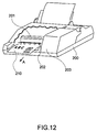
- Fig. 12 shows the appearance of an exemplary inkjet printer 200 according to the present invention in which the drive method of the present invention is employed.
- This inkjet printer 200 has an electrostatic inkjet head 201.
- This electrostatic inkjet head 201 is a line type inkjet head and is basically identical to the inkjet head 1 shown in Fig. 1 to Fig. 3. It has 1440 nozzles arrayed in line opposite the printing paper 210 at a 0.07 mm pitch (360 dpi).
- the inkjet printer 200 further has a paper transport mechanism 202 for advancing the printing paper 210 in the direction of arrow A. Ink droplets are discharged from the inkjet head 201 synchronized to the transport speed of printing paper 210, and the printer thus prints on the paper or other recording medium used in place of paper.
- An ink supply mechanism is accommodated in a compartment 203.
- the ink supply mechanism has an ink tank for storing ink, an ink circulation pump for feeding ink to and recovering ink from the inkjet head 201, and an ink tube connecting the ink tank, circulation pump and inkjet head 201. These various parts of the ink supply mechanism are housed in the compartment 203.
- This inkjet printer 200 further has a head controller 100 (driving means) for implementing the drive method described above.
- This head controller 100 controls the inkjet head 201, the transport mechanism 202, and the ink supply mechanism in response to print data received from a higher device, such as a bar code scanner or other device connected directly thereto or indirectly by way of a network, for example.
- inkjet head 201 of this embodiment is described as a line type head that is held stationary for printing on a printing paper 210 advanced past the inkjet head, it will be obvious that the present invention can also be applied to other types of inkjet printers, including serial printers that print by scanning the recording medium with the inkjet head and discharging ink droplets to the medium synchronized to advancement of the medium.
- An inkjet printer can thus achieve high resolution, precise printing because it uses a high density electrostatic inkjet head 201 driven by a head controller 100 according to this invention. It can also achieve high speed, high resolution printing by means of simple control by the inkjet head.
- the drive method has been described above with reference to an electrostatic inkjet head by way of example only, the method according to the invention can also be applied to other types of inkjet heads that have a pressure chamber and a diaphragm displaceable to change the volume of the pressure chamber. More particularly, the invention can also be used to drive piezoelectric elements using the method shown in Fig. 16 of JP-A-9-314837, for example.
Landscapes
- Particle Formation And Scattering Control In Inkjet Printers (AREA)
- Facsimile Heads (AREA)
Applications Claiming Priority (4)
| Application Number | Priority Date | Filing Date | Title |
|---|---|---|---|
| JP22580999A JP4003353B2 (ja) | 1999-08-09 | 1999-08-09 | 静電式インクジェットヘッドの駆動方法 |
| JP22580999 | 1999-08-09 | ||
| JP2000129934 | 2000-04-08 | ||
| JP2000129934A JP4038958B2 (ja) | 2000-04-28 | 2000-04-28 | 静電式インクジェットヘッドの駆動方法および静電式インクジェットプリンタ |
Publications (4)
| Publication Number | Publication Date |
|---|---|
| EP1075949A2 true EP1075949A2 (de) | 2001-02-14 |
| EP1075949A3 EP1075949A3 (de) | 2001-05-02 |
| EP1075949B1 EP1075949B1 (de) | 2006-11-02 |
| EP1075949B8 EP1075949B8 (de) | 2006-12-20 |
Family
ID=26526841
Family Applications (1)
| Application Number | Title | Priority Date | Filing Date |
|---|---|---|---|
| EP00117084A Expired - Lifetime EP1075949B8 (de) | 1999-08-09 | 2000-08-09 | Antriebsverfahren und Antriebsvorrichtung eines Tintenstrahldruckkopfes |
Country Status (4)
| Country | Link |
|---|---|
| US (1) | US6481833B1 (de) |
| EP (1) | EP1075949B8 (de) |
| AT (1) | ATE344145T1 (de) |
| DE (1) | DE60031609T8 (de) |
Cited By (3)
| Publication number | Priority date | Publication date | Assignee | Title |
|---|---|---|---|---|
| US6428140B1 (en) | 2001-09-28 | 2002-08-06 | Hewlett-Packard Company | Restriction within fluid cavity of fluid drop ejector |
| US6474785B1 (en) | 2000-09-05 | 2002-11-05 | Hewlett-Packard Company | Flextensional transducer and method for fabrication of a flextensional transducer |
| US6685302B2 (en) | 2001-10-31 | 2004-02-03 | Hewlett-Packard Development Company, L.P. | Flextensional transducer and method of forming a flextensional transducer |
Families Citing this family (6)
| Publication number | Priority date | Publication date | Assignee | Title |
|---|---|---|---|---|
| US7334871B2 (en) | 2004-03-26 | 2008-02-26 | Hewlett-Packard Development Company, L.P. | Fluid-ejection device and methods of forming same |
| US7625075B2 (en) * | 2007-07-31 | 2009-12-01 | Hewlett-Packard Development Company, L.P. | Actuator |
| JP2011183764A (ja) * | 2010-03-11 | 2011-09-22 | Seiko Epson Corp | 液体噴射装置 |
| JP5657156B1 (ja) * | 2014-03-31 | 2015-01-21 | ナガセテクノエンジニアリング株式会社 | 静電塗布装置、静電塗布装置用電源装置及び静電塗布方法 |
| JP2018501126A (ja) * | 2015-01-13 | 2018-01-18 | オセ−テクノロジーズ ビーブイ | インクジェットノズルの動作状態を検出するための方法 |
| JP7205224B2 (ja) * | 2018-12-28 | 2023-01-17 | セイコーエプソン株式会社 | 液滴吐出装置および液滴吐出ヘッド |
Citations (4)
| Publication number | Priority date | Publication date | Assignee | Title |
|---|---|---|---|---|
| JPH02289351A (ja) | 1989-02-17 | 1990-11-29 | Ricoh Co Ltd | 記録ヘッド及び記録装置 |
| JPH0569544A (ja) | 1991-04-05 | 1993-03-23 | Ricoh Co Ltd | 液体噴射記録ヘツドの駆動方法 |
| JPH0717039A (ja) | 1993-07-02 | 1995-01-20 | Brother Ind Ltd | インク噴射装置の駆動方法 |
| JPH09314837A (ja) | 1996-03-26 | 1997-12-09 | Seiko Epson Corp | インクジェットヘッド並びにそれを用いた印刷装置及びその制御方法 |
Family Cites Families (9)
| Publication number | Priority date | Publication date | Assignee | Title |
|---|---|---|---|---|
| JPH02187352A (ja) | 1989-07-24 | 1990-07-23 | Seiko Epson Corp | インクジェットヘッド |
| JP2656132B2 (ja) | 1990-03-07 | 1997-09-24 | シャープ株式会社 | インクジェット記録ヘッド |
| JPH0531896A (ja) | 1991-08-02 | 1993-02-09 | Seiko Epson Corp | インクジエツトヘツド |
| JPH05305710A (ja) | 1992-02-24 | 1993-11-19 | Rohm Co Ltd | インクジェットプリントヘッド及びそれを備える電子機器 |
| JPH08295014A (ja) * | 1995-04-26 | 1996-11-12 | Citizen Watch Co Ltd | インクジェットプリンタの記録ヘッドの駆動方法 |
| JP3511766B2 (ja) | 1995-11-29 | 2004-03-29 | セイコーエプソン株式会社 | インクジェットヘッドの駆動方法及びそれを用いたインクジェットプリンタ |
| JPH1016211A (ja) * | 1996-07-05 | 1998-01-20 | Seiko Epson Corp | インクジェット式記録装置 |
| US6234608B1 (en) * | 1997-06-05 | 2001-05-22 | Xerox Corporation | Magnetically actuated ink jet printing device |
| AU755025B2 (en) | 1997-11-28 | 2002-11-28 | Sony Corporation | Apparatus and method for driving recording head for ink-jet printer |
-
2000
- 2000-08-09 AT AT00117084T patent/ATE344145T1/de not_active IP Right Cessation
- 2000-08-09 EP EP00117084A patent/EP1075949B8/de not_active Expired - Lifetime
- 2000-08-09 US US09/635,997 patent/US6481833B1/en not_active Expired - Fee Related
- 2000-08-09 DE DE60031609T patent/DE60031609T8/de active Active
Patent Citations (4)
| Publication number | Priority date | Publication date | Assignee | Title |
|---|---|---|---|---|
| JPH02289351A (ja) | 1989-02-17 | 1990-11-29 | Ricoh Co Ltd | 記録ヘッド及び記録装置 |
| JPH0569544A (ja) | 1991-04-05 | 1993-03-23 | Ricoh Co Ltd | 液体噴射記録ヘツドの駆動方法 |
| JPH0717039A (ja) | 1993-07-02 | 1995-01-20 | Brother Ind Ltd | インク噴射装置の駆動方法 |
| JPH09314837A (ja) | 1996-03-26 | 1997-12-09 | Seiko Epson Corp | インクジェットヘッド並びにそれを用いた印刷装置及びその制御方法 |
Cited By (3)
| Publication number | Priority date | Publication date | Assignee | Title |
|---|---|---|---|---|
| US6474785B1 (en) | 2000-09-05 | 2002-11-05 | Hewlett-Packard Company | Flextensional transducer and method for fabrication of a flextensional transducer |
| US6428140B1 (en) | 2001-09-28 | 2002-08-06 | Hewlett-Packard Company | Restriction within fluid cavity of fluid drop ejector |
| US6685302B2 (en) | 2001-10-31 | 2004-02-03 | Hewlett-Packard Development Company, L.P. | Flextensional transducer and method of forming a flextensional transducer |
Also Published As
| Publication number | Publication date |
|---|---|
| DE60031609D1 (de) | 2006-12-14 |
| US6481833B1 (en) | 2002-11-19 |
| DE60031609T8 (de) | 2007-12-27 |
| EP1075949A3 (de) | 2001-05-02 |
| EP1075949B1 (de) | 2006-11-02 |
| EP1075949B8 (de) | 2006-12-20 |
| ATE344145T1 (de) | 2006-11-15 |
| DE60031609T2 (de) | 2007-09-06 |
Similar Documents
| Publication | Publication Date | Title |
|---|---|---|
| EP0437106B1 (de) | Verfahren und Gerät zum Drucken mit in der Grösse veränderbaren Tintentropfen unter Verwendung eines auf Anforderung reagierenden Tintenstrahl-Druckkopfes | |
| JP5309808B2 (ja) | 液体吐出装置、及び、液体吐出装置の制御方法 | |
| US8662612B2 (en) | Image forming apparatus including recording head for ejecting liquid droplets | |
| US7673953B2 (en) | Liquid ejection apparatus for suppressing a decrease in speed of liquid droplets which are discharged from adjacent nozzles during the same discharge period | |
| US20150116400A1 (en) | Image forming apparatus including recording head for ejecting liquid droplets | |
| EP1911594A1 (de) | Verfahren zur Steuerung eines Tintenstrahldruckkopfes | |
| WO2004096552A1 (en) | Image reproducing/forming apparatus with print head operated under improved driving waveform | |
| US6494555B1 (en) | Ink ejecting device | |
| JPH11216880A (ja) | インクジェットプリンタヘッドの駆動方法 | |
| EP1515854B1 (de) | Kopfsteuervorrichtung und bildaufzeichnungsvorrichtung | |
| EP1075949B1 (de) | Antriebsverfahren und Antriebsvorrichtung eines Tintenstrahldruckkopfes | |
| US6460959B1 (en) | Ink jet recording apparatus | |
| JP4389800B2 (ja) | 液体噴射装置 | |
| JP3912270B2 (ja) | 液体噴射装置 | |
| JP2003182075A5 (de) | ||
| JP4187150B2 (ja) | 液滴吐出ヘッドおよび画像形成装置 | |
| EP1319511B1 (de) | Flüssigkeitsstrahlapparat und Ansteuerverfahren dafür | |
| JP3777705B2 (ja) | インクジェットプリンタにおけるインク吐出制御装置 | |
| JP7105621B2 (ja) | 液体噴射ヘッドおよび液体噴射記録装置 | |
| JP3419372B2 (ja) | インクジェット式記録装置 | |
| JP4038958B2 (ja) | 静電式インクジェットヘッドの駆動方法および静電式インクジェットプリンタ | |
| JP2002059541A (ja) | インクジェットヘッドの駆動方法および駆動装置 | |
| JP4345346B2 (ja) | 静電式インクジェットヘッドの駆動方法、及びインクジェットプリンタ | |
| JP4228599B2 (ja) | インクジェットヘッドの駆動方法 | |
| JP3991680B2 (ja) | 液体噴射装置及び同装置の駆動方法 |
Legal Events
| Date | Code | Title | Description |
|---|---|---|---|
| PUAI | Public reference made under article 153(3) epc to a published international application that has entered the european phase |
Free format text: ORIGINAL CODE: 0009012 |
|
| AK | Designated contracting states |
Kind code of ref document: A2 Designated state(s): AT BE CH CY DE DK ES FI FR GB GR IE IT LI LU MC NL PT SE |
|
| AX | Request for extension of the european patent |
Free format text: AL;LT;LV;MK;RO;SI |
|
| PUAL | Search report despatched |
Free format text: ORIGINAL CODE: 0009013 |
|
| AK | Designated contracting states |
Kind code of ref document: A3 Designated state(s): AT BE CH CY DE DK ES FI FR GB GR IE IT LI LU MC NL PT SE |
|
| AX | Request for extension of the european patent |
Free format text: AL;LT;LV;MK;RO;SI |
|
| 17P | Request for examination filed |
Effective date: 20011016 |
|
| AKX | Designation fees paid |
Free format text: AT BE CH CY DE DK ES FI FR GB GR IE IT LI LU MC NL PT SE |
|
| 17Q | First examination report despatched |
Effective date: 20050208 |
|
| GRAP | Despatch of communication of intention to grant a patent |
Free format text: ORIGINAL CODE: EPIDOSNIGR1 |
|
| GRAS | Grant fee paid |
Free format text: ORIGINAL CODE: EPIDOSNIGR3 |
|
| GRAA | (expected) grant |
Free format text: ORIGINAL CODE: 0009210 |
|
| AK | Designated contracting states |
Kind code of ref document: B1 Designated state(s): AT BE CH CY DE DK ES FI FR GB GR IE IT LI LU MC NL PT SE |
|
| PG25 | Lapsed in a contracting state [announced via postgrant information from national office to epo] |
Ref country code: BE Free format text: LAPSE BECAUSE OF FAILURE TO SUBMIT A TRANSLATION OF THE DESCRIPTION OR TO PAY THE FEE WITHIN THE PRESCRIBED TIME-LIMIT Effective date: 20061102 Ref country code: FI Free format text: LAPSE BECAUSE OF FAILURE TO SUBMIT A TRANSLATION OF THE DESCRIPTION OR TO PAY THE FEE WITHIN THE PRESCRIBED TIME-LIMIT Effective date: 20061102 Ref country code: NL Free format text: LAPSE BECAUSE OF FAILURE TO SUBMIT A TRANSLATION OF THE DESCRIPTION OR TO PAY THE FEE WITHIN THE PRESCRIBED TIME-LIMIT Effective date: 20061102 Ref country code: AT Free format text: LAPSE BECAUSE OF FAILURE TO SUBMIT A TRANSLATION OF THE DESCRIPTION OR TO PAY THE FEE WITHIN THE PRESCRIBED TIME-LIMIT Effective date: 20061102 |
|
| REG | Reference to a national code |
Ref country code: GB Ref legal event code: FG4D |
|
| REG | Reference to a national code |
Ref country code: IE Ref legal event code: FG4D |
|
| REG | Reference to a national code |
Ref country code: CH Ref legal event code: EP |
|
| REF | Corresponds to: |
Ref document number: 60031609 Country of ref document: DE Date of ref document: 20061214 Kind code of ref document: P |
|
| REG | Reference to a national code |
Ref country code: CH Ref legal event code: NV Representative=s name: E. BLUM & CO. PATENTANWAELTE Ref country code: CH Ref legal event code: PK Free format text: DAS PRIORITAETSDATUM WURDE BERICHTIGT: |
|
| PG25 | Lapsed in a contracting state [announced via postgrant information from national office to epo] |
Ref country code: DK Free format text: LAPSE BECAUSE OF FAILURE TO SUBMIT A TRANSLATION OF THE DESCRIPTION OR TO PAY THE FEE WITHIN THE PRESCRIBED TIME-LIMIT Effective date: 20070202 Ref country code: SE Free format text: LAPSE BECAUSE OF FAILURE TO SUBMIT A TRANSLATION OF THE DESCRIPTION OR TO PAY THE FEE WITHIN THE PRESCRIBED TIME-LIMIT Effective date: 20070202 |
|
| PG25 | Lapsed in a contracting state [announced via postgrant information from national office to epo] |
Ref country code: ES Free format text: LAPSE BECAUSE OF FAILURE TO SUBMIT A TRANSLATION OF THE DESCRIPTION OR TO PAY THE FEE WITHIN THE PRESCRIBED TIME-LIMIT Effective date: 20070213 |
|
| PG25 | Lapsed in a contracting state [announced via postgrant information from national office to epo] |
Ref country code: PT Free format text: LAPSE BECAUSE OF FAILURE TO SUBMIT A TRANSLATION OF THE DESCRIPTION OR TO PAY THE FEE WITHIN THE PRESCRIBED TIME-LIMIT Effective date: 20070402 |
|
| NLV1 | Nl: lapsed or annulled due to failure to fulfill the requirements of art. 29p and 29m of the patents act | ||
| ET | Fr: translation filed | ||
| PLBE | No opposition filed within time limit |
Free format text: ORIGINAL CODE: 0009261 |
|
| STAA | Information on the status of an ep patent application or granted ep patent |
Free format text: STATUS: NO OPPOSITION FILED WITHIN TIME LIMIT |
|
| 26N | No opposition filed |
Effective date: 20070803 |
|
| REG | Reference to a national code |
Ref country code: CH Ref legal event code: PFA Owner name: SEIKO EPSON CORPORATION Free format text: SEIKO EPSON CORPORATION#4-1, NISHI-SHINJUKU 2-CHOME#SHINJUKU-KU, TOKYO 163-0811 (JP) -TRANSFER TO- SEIKO EPSON CORPORATION#4-1, NISHI-SHINJUKU 2-CHOME#SHINJUKU-KU, TOKYO 163-0811 (JP) |
|
| PG25 | Lapsed in a contracting state [announced via postgrant information from national office to epo] |
Ref country code: GR Free format text: LAPSE BECAUSE OF FAILURE TO SUBMIT A TRANSLATION OF THE DESCRIPTION OR TO PAY THE FEE WITHIN THE PRESCRIBED TIME-LIMIT Effective date: 20070203 Ref country code: MC Free format text: LAPSE BECAUSE OF NON-PAYMENT OF DUE FEES Effective date: 20070831 |
|
| PG25 | Lapsed in a contracting state [announced via postgrant information from national office to epo] |
Ref country code: IE Free format text: LAPSE BECAUSE OF NON-PAYMENT OF DUE FEES Effective date: 20070809 |
|
| PG25 | Lapsed in a contracting state [announced via postgrant information from national office to epo] |
Ref country code: LU Free format text: LAPSE BECAUSE OF NON-PAYMENT OF DUE FEES Effective date: 20070809 Ref country code: CY Free format text: LAPSE BECAUSE OF FAILURE TO SUBMIT A TRANSLATION OF THE DESCRIPTION OR TO PAY THE FEE WITHIN THE PRESCRIBED TIME-LIMIT Effective date: 20061102 |
|
| PGFP | Annual fee paid to national office [announced via postgrant information from national office to epo] |
Ref country code: CH Payment date: 20100812 Year of fee payment: 11 |
|
| PGFP | Annual fee paid to national office [announced via postgrant information from national office to epo] |
Ref country code: DE Payment date: 20100812 Year of fee payment: 11 Ref country code: FR Payment date: 20100824 Year of fee payment: 11 Ref country code: IT Payment date: 20100817 Year of fee payment: 11 |
|
| PGFP | Annual fee paid to national office [announced via postgrant information from national office to epo] |
Ref country code: GB Payment date: 20100811 Year of fee payment: 11 |
|
| REG | Reference to a national code |
Ref country code: CH Ref legal event code: PL |
|
| GBPC | Gb: european patent ceased through non-payment of renewal fee |
Effective date: 20110809 |
|
| PG25 | Lapsed in a contracting state [announced via postgrant information from national office to epo] |
Ref country code: CH Free format text: LAPSE BECAUSE OF NON-PAYMENT OF DUE FEES Effective date: 20110831 Ref country code: LI Free format text: LAPSE BECAUSE OF NON-PAYMENT OF DUE FEES Effective date: 20110831 |
|
| REG | Reference to a national code |
Ref country code: FR Ref legal event code: ST Effective date: 20120430 |
|
| PG25 | Lapsed in a contracting state [announced via postgrant information from national office to epo] |
Ref country code: IT Free format text: LAPSE BECAUSE OF NON-PAYMENT OF DUE FEES Effective date: 20110809 |
|
| REG | Reference to a national code |
Ref country code: DE Ref legal event code: R119 Ref document number: 60031609 Country of ref document: DE Effective date: 20120301 |
|
| PG25 | Lapsed in a contracting state [announced via postgrant information from national office to epo] |
Ref country code: GB Free format text: LAPSE BECAUSE OF NON-PAYMENT OF DUE FEES Effective date: 20110809 Ref country code: FR Free format text: LAPSE BECAUSE OF NON-PAYMENT OF DUE FEES Effective date: 20110831 |
|
| PG25 | Lapsed in a contracting state [announced via postgrant information from national office to epo] |
Ref country code: DE Free format text: LAPSE BECAUSE OF NON-PAYMENT OF DUE FEES Effective date: 20120301 |