EP1074870A2 - Vorrichtung zum Abisolieren von unmantelten Kabeln - Google Patents
Vorrichtung zum Abisolieren von unmantelten Kabeln Download PDFInfo
- Publication number
- EP1074870A2 EP1074870A2 EP00116725A EP00116725A EP1074870A2 EP 1074870 A2 EP1074870 A2 EP 1074870A2 EP 00116725 A EP00116725 A EP 00116725A EP 00116725 A EP00116725 A EP 00116725A EP 1074870 A2 EP1074870 A2 EP 1074870A2
- Authority
- EP
- European Patent Office
- Prior art keywords
- blade
- cable
- cable guide
- stripping
- blades
- Prior art date
- Legal status (The legal status is an assumption and is not a legal conclusion. Google has not performed a legal analysis and makes no representation as to the accuracy of the status listed.)
- Withdrawn
Links
Images


Classifications
-
- G—PHYSICS
- G02—OPTICS
- G02B—OPTICAL ELEMENTS, SYSTEMS OR APPARATUS
- G02B6/00—Light guides; Structural details of arrangements comprising light guides and other optical elements, e.g. couplings
- G02B6/46—Processes or apparatus adapted for installing or repairing optical fibres or optical cables
- G02B6/56—Processes for repairing optical cables
- G02B6/566—Devices for opening or removing the mantle
Definitions
- the present invention relates to a device for stripping of sheathed cables, in particular of fiber optic wires (Fiber optic core), which is an optical waveguide (Fiber optic) and have an insulating jacket.
- fiber optic wires Fiber optic core
- Fiber optic optical waveguide
- fiber optic wires have been used like other cables stripped at their ends by making the casing ring-shaped or circumferentially separated with the help of a blade after which you strip off the severed part of the casing could.
- the stripping of the separated casing can either directly with the known device the blade itself, or with a separate one Intervention device. Accordingly, includes a generic Device for stripping sheathed cables a cable guide and a blade, the cable routing to it serves to set an exact cutting depth of the blade.
- the known device can only be relatively short Strip the end sections from sheathed cables, otherwise the force required to strip off the severed Sheathing becomes too large.
- the device for stripping sheathed cables, in particular fiber optic wires, with a cable guide and at least one blade is characterized in that the blade is arranged with respect to the cable guide in a manner that removes at least part of the sheathing allowed.
- the sheath is removed by machining in each blade essentially in the direction of extension of the cable, while the cable or the optical waveguide is guided through the device. Accordingly, the stripping can take place over a practically unlimited length, stripping at the central sections of cables or optical fibers also being possible.
- the cable guide advantageously guides the cable to be processed both upstream and downstream of the blade, viewed with respect to the direction of movement of the cable through the device.
- the blade is covered deliverable on the cable guide.
- the device can be different Cable types, especially with different insulation thicknesses or set wire diameter.
- Various arrangements can be made to be deliverable are used, such as those provided in the blade Elongated holes or adjusting screws familiar to a specialist.
- the blade is preferably angular adjustable with regard to the cable routing.
- the blade can be adjusted with respect to the angle of the cable routing the device can be adapted to different cable types. Especially with different sheath thicknesses or also with different materials of the casing can achieve an optimal rake angle through an angular adjustment the blade can be adjusted. If an example Stripping cable with a thin sheath should be the angle the blade as flat as possible with respect to the cable routing be set so that when the insulation is removed Not the cable itself and especially the wire contained in it deformed. This can damage the wire by the Blade to be avoided.
- the blade forms an angle with the cable from between 10 and 60 °, in particular from between 30 and 45 °. In a particularly preferred embodiment forms the blade forms an angle of approximately 37 ° with the cable.
- the angular ranges given above have been found to be suitable Rake angle for currently available cables and fiber optic wires shown.
- the device advantageously comprises a Spanumlenkabêt so that the separated Chip can move freely.
- the chip deflection section can for example an inclined surface or a curved surface if, for example, a spiral formation of the separated Spanes is desired.
- the cable routing Downstream of the blade in size and / or shape adapted the processed cable can improve cable routing become.
- the cable routing points above the blade when using a cable or an optical fiber core with a circular cut a corresponding one circular diameter, which is below the blade practically merges into the shape of an oval or the shape of a circle minus one segment of a circle per used Blade matches.
- This configuration allows twisting or twisting of the cable in the device be avoided, so that when using, for example, only the blade stripping the cable can take place at a predetermined position of the cable.
- the cable routing is advantageously at least partially funnel-shaped. If, for example, the introductory is funnel-shaped, the user can more easily the cable or the fiber optic wire into the device insert even if the cable routing the cable practical can record without play. Furthermore, the funnel-shaped Shaping the risk of damage to the Cable is reduced by bending on edges.
- the device preferably comprises a support element with a Cavity. Part of the device, including the cable routing, the blade holder and the blade itself can are carried by the support element in such a way that the stripped cable in or through the cavity of the Support body can occur.
- the stripping length is advantageously determined by the dimension the support body and / or the cavity is determined. If for example after stepping on the blade or the Sound the stripped cable in the cavity of the support body is guided and the cavity has a bottom surface, so the cable can be stripped until the end is the bottom surface touched. This allows a preset stripping length on a large number of cables or optical fibers become.
- the device according to the invention with any Number of blades can be provided, it is preferred that an even number of blades is provided, in particular face each other. If for example two each other opposite blades on both sides with the one to be machined If cables engage, a balance of forces can be formed be, so that a deformation of the cable, and in particular the vein, does not take place.
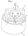
- the device consists of an embodiment upper part and a support body designed as a hollow cylinder 14.
- the upper part comprises a base plate 2 and one blade holder portion connected to the base plate 2 10.
- Section 10 has an opening at its upper end on, which forms the beginning of the cable guide 20.
- this cable duct 20 is one in the illustrated embodiment Cable 1 inserted.
- a blade 27 is received, which by means of a Jaw 30 and screws 32 is fixed.
- the illustrated Embodiment is also that of the cable 1 machined separated part of the insulation shown, which after the Cut off on the visible side of the blade. The remaining rest of the cable runs in the illustrated Embodiment behind the blade and is therefore not visible.
- the cutting edge which is located at the upper end of the blade 27, completely covered by the jaw 30 so that it is protected from external influences is protected. Furthermore, a user can due to the concealed arrangement of the cutting edge on the device overall hardly hurt.
- the surface 3 of the base plate 2 serves as chip deflection in the illustrated embodiment, so that the separated chip of insulation material is distracted.
- the upper part of the device on a hollow cylindrical support body 40 stored.
- the support body 40 comprises a base 46, on which the upper part can rest.
- the hollow cylinder 40 also has a cavity 42 in which the Cable can occur after stripping.
- the support body has a circumferential bead 44 which a stop edge for the base surface 2 of the upper part Are defined.
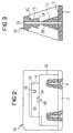
- Fig. 2 is the upper part of the device shown in Fig. 1 shown in side view, parts for clarification are broken away, and being the one shown in FIG Jaw 30 with the screws 32 and the blade 27 not shown are.
- the base plate 2 is by means of screw 4 with the screwed upper section 10.
- the upper section 10 which in the embodiment shown is milled from aluminum or a similar metal, a recess 12, which is suitable for receiving the blade is.
- a recess 12 which is suitable for receiving the blade is.
- Fig. 3 is a cross-sectional view of the upper part as shown in Fig. 2.
- the sectional view runs essentially in the middle by the representation of Fig. 2 and shows the cable guide 20 in the middle of it.
- the cable guide 20 is the cable guide 20 at the top with a Funnel 21 provided the introduction of the to be processed Cable relieved.
- the cable guide 20 also extends through the base plate 2.
- the recess 12 provides a contact surface 11 which can rest the blade 27, not shown.
- the contact surface 11 is angled with respect to the cable guide 20, the upper End of a blade is made possible, at least partially in the To protrude cable guide 20.
- the insulation can be lifted off the cable.
- the recesses 14 and 16 form a receiving space for the jaw intended for fastening the blade 30.
- various delivery and / or adjustment mechanisms are provided especially the position of the blade with regard to the angle or also with respect to the Degree at which the blade protrudes into the cable guide 20 can.
- the illustrated embodiment are on both Symmetrical arrangements are made on both sides of the Arrange two opposing blades for the cable to be processed to be able to.
- FIG. 4a, b and c each show one Front view, side view and top view of the in Fig. 1 jaw 30 shown for fixing the blade 27 serves.
- the jaw 30 corresponds essentially in shape the recesses 14, 16 and shown in Fig. 2 comprises Bores 32 that are aligned with the bores 18 of the section 10 are aligned.
- these holes 32 also as elongated holes be formed and additionally or alternatively an angular Allow adjustability.
- On the configurations of the angular and positional adjustment of the blade should not discussed further here as these options are familiar to the expert. However, it should be mentioned that, for example, by designing the inclined surface 36 a corresponding inclination of the blade can be achieved can.
- the Jaw 30 has a recess 37 at a corresponding position on.
- FIGS. 5a and 5b the one shown in FIG. 1 is also shown Support body 40 shown in detail.
- the support body 40 is also made of aluminum in the embodiment shown or other suitable material and has a height sufficient to at least the desired length of stripped cable.
- At the The upper side of the support body 40 has a support surface 46 on which the upper part at least partially rest can. This support surface 46 preferably runs essentially parallel to the bottom plate 2 of the upper part.
- the Stand area 46 can also provide an additional span deflection function meet, as shown in Fig. 1. To a Slipping of the upper part with respect to the support element 40 to avoid, this has an at least partially revolving Bead 44.
- any sections and any Stripped lengths of cables, especially fiber optic wires can be.
- the device enables a versatile Use and can be adjusted to different Parameters of the cable to be processed, such as Overall cable diameter, sheath thickness, material properties the sheathing and so on.
- the specialist will further recognize that various modifications regarding the described preferred embodiment possible are, as included in the claims or as Equivalents have to be considered. These include in particular various material selections for the device itself, different types of blades, such as razor blades, as well as the multiple-addressed delivery and adjustment options, that are familiar to the expert.
Landscapes
- Physics & Mathematics (AREA)
- General Physics & Mathematics (AREA)
- Optics & Photonics (AREA)
- Removal Of Insulation Or Armoring From Wires Or Cables (AREA)
- Light Guides In General And Applications Therefor (AREA)
Abstract
Description

Claims (12)
- Vorrichtung zum Abisolieren von ummantelten Kabeln, insbesondere von Lichtwellenleiter-Adern mit einer Kabelführung (20) und zumindest einer Klinge (27), dadurch gekennzeichnet, daß die Klinge (27) mit Bezug auf die Kabelführung (20) in einer Weise angeordnet ist, die ein Abspanen von zumindest einem Teil der Ummantelung erlaubt.
- Vorrichtung nach Anspruch 1, dadurch gekennzeichnet, daß die Klinge (27) mit Bezug auf die Kabelführung (20) zustellbar ist.
- Vorrichtung nach Anspruch 1 oder 2, dadurch gekennzeichnet, daß die Klinge (27) mit Bezug auf die Kabelführung winkelmäßig einstellbar ist.
- Vorrichtung nach einem der Ansprüche 1 bis 3, dadurch gekennzeichnet, daß die Klinge (27) mit dem Kabel (1) einen Winkel von zwischen 10° und 60°, insbesondere von zwischen 30° und 45° bildet.
- Vorrichtung nach einem der vorangegangenen Ansprüche, dadurch gekennzeichnet, daß ein Spanumlenkabschnitt (3, 46) vorgesehen ist.
- Vorrichtung nach einem der vorangegangenen Ansprüche, dadurch gekennzeichnet, daß die Kabelführung (20) flußabwärts der Klinge (27) liegend größen- und/oder formmäßig auf das bearbeitete Kabel angepaßt ist.
- Vorrichtung nach einem der vorangegangenen Ansprüche, dadurch gekennzeichnet, daß die Kabelführung (20) zumindest teilweise trichterförmig ausgebildet ist.
- Vorrichtung nach einem der vorangegangenen Ansprüche, dadurch gekennzeichnet, daß sie ein Stützelement (40) mit einem Hohlraum (42) aufweist.
- Vorrichtung nach Anspruch 8, dadurch gekennzeichnet, daß die Abisolierlänge durch die Abmessungen des Stützkörpers (40)und/oder des Hohlraumes (42) bestimmt ist.
- Vorrichtung nach einem der vorangegangenen Ansprüche, dadurch gekennzeichnet, daß die Schneidkante der Klinge (27) vollständig verdeckt ist.
- Vorrichtung nach einem der vorangegangenen Ansprüche, dadurch gekennzeichnet, daß zwei Klingen (27) vorgesehen sind, die insbesondere einander gegenüberliegend beidseitig des Kabels (1) angeordnet sind.
- Vorrichtung nach Anspruch 11, dadurch gekennzeichnet, daß die zwei Klingen (27) voneinander um zumindest den Durchmesser der Ader des Kabels (1) beabstandet sind.
Applications Claiming Priority (2)
| Application Number | Priority Date | Filing Date | Title |
|---|---|---|---|
| DE19936345 | 1999-08-02 | ||
| DE19936345A DE19936345A1 (de) | 1999-08-02 | 1999-08-02 | Vorrichtung zum Abisolieren von ummantelten Kabeln |
Publications (2)
| Publication Number | Publication Date |
|---|---|
| EP1074870A2 true EP1074870A2 (de) | 2001-02-07 |
| EP1074870A3 EP1074870A3 (de) | 2001-05-30 |
Family
ID=7916916
Family Applications (1)
| Application Number | Title | Priority Date | Filing Date |
|---|---|---|---|
| EP00116725A Withdrawn EP1074870A3 (de) | 1999-08-02 | 2000-08-02 | Vorrichtung zum Abisolieren von unmantelten Kabeln |
Country Status (2)
| Country | Link |
|---|---|
| EP (1) | EP1074870A3 (de) |
| DE (1) | DE19936345A1 (de) |
Families Citing this family (1)
| Publication number | Priority date | Publication date | Assignee | Title |
|---|---|---|---|---|
| DE20214365U1 (de) | 2002-09-16 | 2002-11-21 | Klann Tools Ltd., Oxfordshire | Vorrichtung zum Entmanteln einer Bremsleitung |
Family Cites Families (2)
| Publication number | Priority date | Publication date | Assignee | Title |
|---|---|---|---|---|
| DE4236251A1 (de) * | 1992-10-20 | 1994-04-21 | Hoechst Ag | Vorrichtung zum Entfernen der Schutzhülle von Optischen Fasern |
| DE4416817A1 (de) * | 1994-05-13 | 1995-11-16 | Rehau Ag & Co | Schneidwerkzeug |
-
1999
- 1999-08-02 DE DE19936345A patent/DE19936345A1/de not_active Withdrawn
-
2000
- 2000-08-02 EP EP00116725A patent/EP1074870A3/de not_active Withdrawn
Also Published As
| Publication number | Publication date |
|---|---|
| DE19936345A1 (de) | 2001-02-08 |
| EP1074870A3 (de) | 2001-05-30 |
Similar Documents
| Publication | Publication Date | Title |
|---|---|---|
| DE3856256T2 (de) | Gerät zum Schneiden einer optischen Glasfaser | |
| DE69831996T2 (de) | Handwerkzeug | |
| EP3069419B1 (de) | Vorrichtung zum verschweissen von elektrischen leitern | |
| EP1560310B1 (de) | Abisolierzange | |
| DE2721437C2 (de) | Abisolierwerkzeug für Draht | |
| DE2849975A1 (de) | Verbindungsstecker fuer ein optisches mehrfaser-kabel | |
| EP0306710B1 (de) | Rasierklingeneinheit | |
| EP1557920B1 (de) | Abisolierzange mit automatischer Anpassung an verschiedene Leiterquerschnitte | |
| DE69633897T2 (de) | Abisoliervorrichtung für Faserbändchen | |
| DE4236251A1 (de) | Vorrichtung zum Entfernen der Schutzhülle von Optischen Fasern | |
| EP1816716B1 (de) | Abmantelwerkzeug | |
| EP0682273A1 (de) | Schneidwerkzeug | |
| EP2523265B1 (de) | Zugentlastungs-/Biegeschutzvorrichtung | |
| DE102020133953B3 (de) | Abisoliereinheit eines Presswerkzeugs, Presswerkzeug und Verfahren zur Montage einer Einstelleinheit | |
| EP0610841A2 (de) | Kabelschneider für Schnitte längs der Mantellinie und der Umfangslinie | |
| DE19936345A1 (de) | Vorrichtung zum Abisolieren von ummantelten Kabeln | |
| DE19543390C1 (de) | Abisoliergerät | |
| DE2932501C2 (de) | Abisoliergerät | |
| DE1222763C2 (de) | Spanabhebendes werkzeug | |
| EP0140038A2 (de) | Abisoliergerät für Kabelenden | |
| DE60100137T2 (de) | Werkzeug zum Abschneiden eines Wellrohres | |
| DE10112930C1 (de) | Verfahren und Vorrichtung zum Durchtrennen einer Schweißelektrode an einer bestimmten Trennstelle | |
| EP1365714B1 (de) | Klingenhalterung für ein chirurgisches instrument und verfahren zur befestigung einer klinge | |
| DE3100954C2 (de) | Vorrichtung zum Anschneiden des Faserkernes einer optischen Leitung | |
| DE2629208A1 (de) | Abmantelwerkzeug fuer lichtwellenleiter-einzeladern |
Legal Events
| Date | Code | Title | Description |
|---|---|---|---|
| PUAI | Public reference made under article 153(3) epc to a published international application that has entered the european phase |
Free format text: ORIGINAL CODE: 0009012 |
|
| AK | Designated contracting states |
Kind code of ref document: A2 Designated state(s): AT BE CH CY DE DK ES FI FR GB GR IE IT LI LU MC NL PT SE |
|
| AX | Request for extension of the european patent |
Free format text: AL;LT;LV;MK;RO;SI |
|
| PUAL | Search report despatched |
Free format text: ORIGINAL CODE: 0009013 |
|
| AK | Designated contracting states |
Kind code of ref document: A3 Designated state(s): AT BE CH CY DE DK ES FI FR GB GR IE IT LI LU MC NL PT SE |
|
| AX | Request for extension of the european patent |
Free format text: AL;LT;LV;MK;RO;SI |
|
| 17P | Request for examination filed |
Effective date: 20011110 |
|
| RAP1 | Party data changed (applicant data changed or rights of an application transferred) |
Owner name: CCS TECHNOLOGY, INC. |
|
| AKX | Designation fees paid |
Free format text: AT BE CH CY DE DK ES FI FR GB GR IE IT LI LU MC NL PT SE |
|
| STAA | Information on the status of an ep patent application or granted ep patent |
Free format text: STATUS: THE APPLICATION IS DEEMED TO BE WITHDRAWN |
|
| 18D | Application deemed to be withdrawn |
Effective date: 20040302 |