EP3069419B1 - Vorrichtung zum verschweissen von elektrischen leitern - Google Patents
Vorrichtung zum verschweissen von elektrischen leitern Download PDFInfo
- Publication number
- EP3069419B1 EP3069419B1 EP14803063.8A EP14803063A EP3069419B1 EP 3069419 B1 EP3069419 B1 EP 3069419B1 EP 14803063 A EP14803063 A EP 14803063A EP 3069419 B1 EP3069419 B1 EP 3069419B1
- Authority
- EP
- European Patent Office
- Prior art keywords
- edge
- stop
- axial direction
- stop edge
- sonotrode
- Prior art date
- Legal status (The legal status is an assumption and is not a legal conclusion. Google has not performed a legal analysis and makes no representation as to the accuracy of the status listed.)
- Revoked
Links
Images

Classifications
-
- B—PERFORMING OPERATIONS; TRANSPORTING
- B23—MACHINE TOOLS; METAL-WORKING NOT OTHERWISE PROVIDED FOR
- B23K—SOLDERING OR UNSOLDERING; WELDING; CLADDING OR PLATING BY SOLDERING OR WELDING; CUTTING BY APPLYING HEAT LOCALLY, e.g. FLAME CUTTING; WORKING BY LASER BEAM
- B23K20/00—Non-electric welding by applying impact or other pressure, with or without the application of heat, e.g. cladding or plating
- B23K20/10—Non-electric welding by applying impact or other pressure, with or without the application of heat, e.g. cladding or plating making use of vibrations, e.g. ultrasonic welding
-
- H—ELECTRICITY
- H01—ELECTRIC ELEMENTS
- H01R—ELECTRICALLY-CONDUCTIVE CONNECTIONS; STRUCTURAL ASSOCIATIONS OF A PLURALITY OF MUTUALLY-INSULATED ELECTRICAL CONNECTING ELEMENTS; COUPLING DEVICES; CURRENT COLLECTORS
- H01R43/00—Apparatus or processes specially adapted for manufacturing, assembling, maintaining, or repairing of line connectors or current collectors or for joining electric conductors
- H01R43/02—Apparatus or processes specially adapted for manufacturing, assembling, maintaining, or repairing of line connectors or current collectors or for joining electric conductors for soldered or welded connections
- H01R43/0263—Apparatus or processes specially adapted for manufacturing, assembling, maintaining, or repairing of line connectors or current collectors or for joining electric conductors for soldered or welded connections for positioning or holding parts during soldering or welding process
-
- B—PERFORMING OPERATIONS; TRANSPORTING
- B23—MACHINE TOOLS; METAL-WORKING NOT OTHERWISE PROVIDED FOR
- B23K—SOLDERING OR UNSOLDERING; WELDING; CLADDING OR PLATING BY SOLDERING OR WELDING; CUTTING BY APPLYING HEAT LOCALLY, e.g. FLAME CUTTING; WORKING BY LASER BEAM
- B23K2101/00—Articles made by soldering, welding or cutting
- B23K2101/36—Electric or electronic devices
- B23K2101/38—Conductors
Definitions
- the present invention relates to an apparatus for welding rod-shaped electrical conductors provided with an outer insulating sheath, having sheath-free blank regions whose length is defined by an axial sheath end surface comprising a compression space for receiving connecting regions of the conductors to be connected to each other, wherein the compression space in a first axis direction on two opposite sides by a working surface of a sonotrode transmitting ultrasonic vibrations in the first axis direction and a counter surface of a counter electrode and in a second axis direction on two opposite sides by a boundary surface of a movable in the second axis direction slider element and a Limiting surface of a limiting element is limited, wherein the compression space has at least one guide element, which ang laterally to the slide element eordnet and relative to the slider element in the second axis direction is movable, and the guide element has a leading edge for positioning a conductor in the second axis direction relative to the boundary surface of the limiting element.
- a device of the type mentioned is from the EP 1 765 545 A1 known.
- conductors to be welded together are inserted into the open compression space with their blank regions such that the blank regions of the conductors with sections which form the connection regions of the welding node when subjected to oscillation by the sonotrode in a first axial direction, in a mutually overlapping stack arrangement aligned parallel to each other in front of the slider element opposite the boundary surface of the limiting element are positioned.
- the slider element of the known device is arranged laterally to the slider element and provided in the second axis direction, ie parallel to the travel of the slider element guiding elements, each having a leading edge, which in a preferred embodiment to the boundary surface the boundary element is inclined, so that the guide edges together with the boundary surface of the limiting element form a V-shaped recess which ensures the desired unique positioning of the blank areas of the conductors in the second axis direction when inserting the conductor in the open compression space.
- the correct positioning of the blank areas in the compression space in the longitudinal axis direction of the conductors, ie in a third axis direction is such that the connection areas are in the desired position in the subsequent vibration application Length train, depending on the skill of the manager in the compaction room inserting operator.
- the present invention is therefore based on the object to improve the manufacturing quality in the production of ultrasonic welded joints.
- the guide element is provided with a stop edge for axial positioning of the envelope end face, wherein the distance of the stop edge of the working surface of the sonotrode is selected so that in a stop of Umhüllungsend components against the stop edge and in a third axis parallel to the working surface of the sonotrode and the boundary surface of the boundary element aligned blank area, the blank area extends with a defined length within the compression space.
- the device according to the invention thus makes it possible for an operator when inserting the blank area of the conductors into the open compression space only to ensure that the envelope end faces of the conductors abut against the stop edge of the guide element to ensure that the blank area of the conductor is defined with a section Length projects into the compression space.
- the positioning of the conductors in their longitudinal axis direction is thus no longer dependent on the "eye size" of the operator, but is reproducibly adjustable by means of the stop edge.
- the conductors which are welded together in the apparatus according to the invention are generally rod-shaped conductors, that is to say essentially conductors dimensioned in their dimension by the longitudinal extent, which have an at least low flexural rigidity, as long as no radial load on the conductors acts - despite flexible training to maintain their longitudinal extent.
- Such conductors can be formed, for example, as an insulated strand, which, in particular in the form of a strand, is bundled into bundles of strands of a plurality of strands and inserted into the compression space.
- the stop edge has an edge thickness which is smaller than 2 mm, so that the desired effect of the stop edge as resistance to axial displacement of the wrap end beyond the stop edge also still exists when a conductor with a low relative inclination to the stop edge in the direction is moved to the stop edge.
- the edge thickness of the stop edge is formed, the more pronounced the stop effect can be realized; even if, due to a coating designed with a particularly low layer thickness, the wrapping end surface forms a shoulder of minimal height relative to the blank area, so that the heel could readily slide over an edge with a comparatively much greater edge strength even at a low relative inclination to the stop edge.
- edge thickness which is smaller than 1.5 mm or even less than 1 mm, the choice of the actual edge strength ultimately represents a compromise between the desired stop action and about avoiding a risk of injury to the operator too low edge thickness, so too sharp edges.
- the guide element is provided with a feed device which is a positioning of the stop edge relative to the working surface of Sonotrode allows in the third axis direction, can be set in a comfortable or very time-saving manner, the length of the section with which the blank area protrudes into the compression space, changeable.
- the positioning of the stop edge can be adjusted via an adjustment of the guide element relative to the slide element.
- an adaptation of the desired positioning of the stop edge may optionally be made via the replacement of the stopper body.
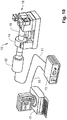
- Fig. 10 shows the basic arrangement of components of an ultrasonic welding apparatus 10, which includes a converter 12, a booster 14 and a sonotrode 16.
- the sonotrode 16 or one of these associated counter electrode 21 limit, as in particular in Fig.1 is shown, in a first axis direction (z-axis), a compression chamber 18 which is adjustable in height and width in order to adjust the cross section of the compression chamber 18 to the number or cross section of the conductors to be welded together.
- the converter 12 is connected via a line 11 to a generator 13, which in turn is connected via a line 15 to a computer 17 to input welding parameters or the cross-sectional geometry of the conductors to be welded together.
- the power output of the generator 13 can then be determined in order to retrieve the required welding parameters by means of a program stored in the computer 17 and to generate ultrasonic vibrations correspondingly by means of the converter 12, which are transmitted via the booster 14 to the sonotrode 16 or its working surface 19 (FIG. Fig.1 ) be transmitted.
- the Fig. 1 and 4 show the essential elements of the adjustable cross-section, so in the embodiments in height and width adjustable compression chamber 18.
- the compression chamber 18 is in the first axis direction (z-axis) on two opposite sides bounded by a working surface 19 of the ultrasonic vibrations sonotrode 16 and a mating surface 20 of a movable in a second axis direction (y-axis) counter electrode 21.
- a working surface 19 of the ultrasonic vibrations sonotrode 16 and a mating surface 20 of a movable in a second axis direction (y-axis) counter electrode 21.
- y-axis second axis direction
- the compression space 18 is bounded on two opposite sides by a boundary surface 22 of a movable in the y-axis direction slider element 23 and a boundary surface 24 of the same as the counter electrode 21 movable in the z-axis direction limiting element 25.
- FIG. 1 illustrated embodiment of the compression chamber 18 are two stacked arrangement one above the other arranged connecting portions 26, 27 of each other by means of an ultrasonic welding connection to be connected conductors 28, 29 on the working surface 19 of the sonotrode 16, said Fig. 1 the connecting regions 26, 27 immediately after insertion into the open compression chamber 18 shows.
- Fig. 4 shows the compression chamber 18 in the closed configuration in which the compaction space 18 delimiting components, so the sonotrode 16, the counter electrode 21, the slider element 23 and the limiting element 25, are moved against each other so that the now reduced in its volume compression space 18 a Form 37 forms, which allows for an application of the connecting portions 26, 27 of the conductors 28, 29 with mechanical vibrations of the sonotrode 16 in a friction welding a compression and connection of the connecting portions 26, 27 with each other to form a welding node.
- the compression space 18 is provided with a guide 40, which in the present case comprises two guide elements 41, 42, which are arranged on both sides of the slide element 23 and, as by the in Fig. 1 registered double arrow is illustrated relative to the slide element 23 in the second axis direction (y-axis) are displaceable.
- the guide elements 41, 42 are each provided with a stop edge 43 for the axial positioning of the connecting regions 26, 27 of the conductors 28, 29 in the third axis direction (x-axis) in the compression space 18.
- the abutment edges 43 in the case of the present embodiment of the guide 40 are formed as guide edges, which serve to insert the blank areas 33, 34 of the conductors 28, 29 in the open compression space 18, the blank areas 33, 34 in the second axis direction (y -Axis) so that the blank areas 33, 34 abut the boundary surface 24 of the limiting element 25 or at least immediately adjacent to the boundary surface 24 are arranged.
- Fig. 2 shows, thus determines the axial abutment of the envelope end faces 35, 36 against the stop edges 43, the length l, with which the blank portions 33, 34 of the conductors 28, 29 protrude into the compression space 18.
- FIG. 2 By way of example, illustrated stacking arrangement of the blank portions 33, 34, which serves to produce a passage welding node 38 so that the interconnected via the passage welding node 38 conductors 28, 29 extend in opposite directions, thus defining the stop edges 43 of the guide elements 41, 42, the respective length l with which the blank areas 33, 34 from different directions in the third axis direction (x-axis) in Compaction space 18 extend, whereby on the one hand, the length l 1 of the connecting portions 26, 27 of the blank areas 33, 34 and thus the length of the through-welding node 38 produced by the ultrasonic welding process is defined.
- the length l with which the blank regions 33, 34 extend in the connection space 18, defines the length l 2 , that is, after the passage welding node 38 has been produced between the envelope end faces 35, 36 of the conductors 28, 29 and the connection regions 26, 27, ie the passage welding node 38, remaining distance.
- the desired node geometry is predetermined by the stop edges 43 formed on the guide elements 41, 42.
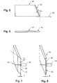
- FIGS. 5 and 6 is a guide element 41 mit a stop edge 43, which serves as a leading edge for the above-described radial positioning of the conductors 28, 29 and an inclination angle ⁇ relative to a through the working surface 19 of the sonotrode 16 (16).
- Fig.1 defined working level 39, shown in individual representation.
- the angle of inclination ⁇ is preferably chosen according to the number and the diameter of the inserted into the compression space conductor and is usually between 20 and 60 °.
- Fig. 7 shows that the stop edge 43 is formed as an edge provided with a one-sided bevel having an edge angle ⁇ , so that an edge thickness s 1 is minimized and the edge thickness s practically goes to zero.
- Fig. 8 shows an alternative embodiment of a guide member 45 having a stop edge formed as a step edge 46, which is formed by a stepped configuration of a leading edge of the guide element 45.
- FIGS. 7 and 8 the axial abutment end surface 35 of a conductor 28 against the stop edge 43 and 46th
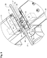
- stop edges 47 as stepped edges is also the in Fig. 9 shown embodiment of guide elements 48, 49 can be seen.
- the stop edges 47 are formed on a arranged on the respective guide element 48, 49 stop body 50.
- the stopper body 50 are releasably connected in the present case via screw 51 with a carrier 52 of the respective guide element 48, 49.
- the stop edge 47 of the guide elements 48, 49 serves to guide the edge when the blank areas 33, 34 of the conductors 28, 29 are in each case connected to the boundary surface 24 of the delimiting element 25 and the working surface 19 of the sonotrode 16 inclined, such that the blank portions 33, 34 are radially positioned along a radially guide along the stop edges 47 immediately adjacent to the boundary surface 24 on the working surface 19 of the sonotrode 16.
- the stop edges 47 ensure that, in the case of axial abutment of the envelope end faces 35, 36, the blank regions 33, 34 extend into the opened compression chamber 18 with a defined length l ( Fig. 2 ).
- the height h or the supernatant of the stop edges relative to the carrier 52 in the radial direction with respect to the longitudinal axis 44 of the conductors 28, 29 selected so that the height h is at least so great that a radial contact between the stop edges 47 and Blank areas 33, 34 is given and thus a secure axial support of the envelope end faces 35, 36 is ensured at the stop edges 47.
Description
- Die vorliegende Erfindung betrifft eine Vorrichtung zum Verschweißen von stabförmigen, mit einer äußeren isolierenden Umhüllung versehenen elektrischen Leitern, die von der Umhüllung befreite Blankbereiche aufweisen, deren Länge durch eine axiale Umhüllungsendfläche definiert ist, umfassend einen Verdichtungsraum zur Aufnahme von miteinander zu verbindenden Verbindungsbereichen der Leiter, wobei der Verdichtungsraum in einer ersten Achsenrichtung an zwei einander gegenüberliegenden Seiten durch eine Arbeitsfläche einer in die erste Achsenrichtung Ultraschallschwingungen übertragenden Sonotrode und eine Gegenfläche einer Gegenelektrode sowie in einer zweiten Achsenrichtung an zwei einander gegenüberliegenden Seiten durch eine Begrenzungsfläche eines in die zweite Achsenrichtung verfahrbaren Schieberelements und eine Begrenzungsfläche eines Begrenzungselements begrenzt ist, wobei der Verdichtungsraum zumindest ein Leitelement aufweist, das seitlich zum Schieberelement angeordnet und relativ zum Schieberelement in die zweite Achsenrichtung bewegbar ist, und das Leitelement eine Führungskante zur Positionierung eines Leiter in der zweiten Achsenrichtung relativ zur Begrenzungsfläche des Begrenzungselements aufweist.
- Eine Vorrichtung der eingangs genannten Art ist aus der
EP 1 765 545 A1 bekannt. Vor Durchführung des Ultraschallschweißvorgangs werden miteinander zu verschweißende Leiter mit ihren Blankbereichen so in den geöffneten Verdichtungsraum eingelegt, dass die Blankbereiche der Leiter mit Abschnitten, die die Verbindungsbereiche des Schweißknotens bei einer Schwingungsbeaufschlagung durch die Sonotrode in einer ersten Achsenrichtung ausbilden, in einer einander überdeckenden Stapelanordnung und parallel zueinander ausgerichtet vor der dem Schieberelement gegenüberliegenden Begrenzungsfläche des Begrenzungselements positioniert sind. Um diese Relativpositionierung gegenüber der Begrenzungsfläche zu erzielen, ist das Schieberelement der bekannten Vorrichtung mit seitlich zum Schieberelement angeordneten und sich in die zweite Achsenrichtung, also parallel zum Verfahrweg des Schieberelements erstreckenden Leitelementen versehen, die jeweils eine Führungskante aufweisen, welche in einer bevorzugten Ausführungsform zur Begrenzungsfläche des Begrenzungselements hin geneigt verläuft, sodass die Führungskanten zusammen mit der Begrenzungsfläche des Begrenzungselements eine V-förmig ausgebildete Ausnehmung ausbilden, die beim Einlegen der Leiter in den geöffneten Verdichtungsraum für die gewünschte eindeutige Positionierung der Blankbereiche der Leiter in der zweiten Achsenrichtung sorgt. - Im Gegensatz zu der vorstehend erläuterten Positionierungshilfe zur korrekten Positionierung der Blankbereiche der Leiter in der zweiten Achsenrichtung ist die korrekte Positionierung der Blankbereiche im Verdichtungsraum in Längsachsenrichtung der Leiter, also in einer dritten Achsenrichtung, derart, dass sich bei der nachfolgenden Schwingungsbeaufschlagung die Verbindungsbereiche in der gewünschten Länge ausbilden, vom Geschick der die Leiter in den Verdichtungsraum einlegenden Bedienperson abhängig.
- Hierdurch ist es möglich, dass letztendlich fehlerhafte Schweißknoten hergestellt werden oder geringstenfalls nicht sichergestellt werden kann, dass Toleranzvorgaben betreffend die geometrischen Parameter des Schweißknotens, also insbesondere die Länge der Verbindungsbereiche, nicht eingehalten werden können.
- Der vorliegenden Erfindung liegt daher die Aufgabe zugrunde, die Fertigungsqualität bei der Herstellung von Ultraschallschweißverbindungen zu verbessern.
- Diese Aufgabe wird durch eine Vorrichtung mit den Merkmalen des Anspruchs 1 gelöst.
- Bei der erfindungsgemäßen Vorrichtung ist das Leitelement mit einer Anschlagkante zur axialen Positionierung der Umhüllungsendfläche versehen, wobei der Abstand der Anschlagkante von der Arbeitsfläche der Sonotrode so gewählt ist, dass bei einem Anschlag der Umhüllungsendfläche gegen die Anschlagkante und in einer dritten Achsenrichtung parallel zur Arbeitsfläche der Sonotrode und der Begrenzungsfläche des Begrenzungselements ausgerichtetem Blankbereich sich der Blankbereich mit einer definierten Länge innerhalb des Verdichtungsraumes erstreckt.
- Die erfindungsgemäße Vorrichtung ermöglicht es also, dass eine Bedienperson beim Einlegen der Blankbereichs der Leiter in den geöffneten Verdichtungsraum lediglich noch darauf achten muss, dass die Umhüllungsendflächen der Leiter gegen die Anschlagkante des Leitelements anschlagen, um sicherzustellen, dass der Blankbereich des Leiters mit einem Abschnitt definierter Länge in den Verdichtungsraum hineinragt.
- Die Positionierung der Leiter in deren Längsachsenrichtung ist somit nicht mehr abhängig vom "Augenmaß" der Bedienperson, sondern ist vermittels der Anschlagkante reproduzierbar einstellbar.
- Bei den in der erfindungsgemäßen Vorrichtung miteinander verschweißten Leitern handelt es sich in der Regel um stabförmige, also im Wesentlichen in ihrer Dimension durch die Längserstreckung bestimmte Leiter, die eine zumindest geringe Biegesteifigkeit aufweisen, um - solange keine radiale Belastung auf die Leiter wirkt - trotz flexibler Ausbildung ihre Längserstreckung beizubehalten. Derartige Leiter können beispielsweise als eine isolierte Litze ausgebildet sein, die, insbesondere in der Ausbildung als Litze zu Litzenpaketen aus einer Mehrzahl von Litzen zusammengefasst, in den Verdichtungsraum eingelegt werden.
- Vorzugsweise weist die Anschlagkante eine Kantenstärke auf, die kleiner ist als 2 mm, sodass die gewünschte Wirkung der Anschlagkante als Widerstand gegen eine axiale Verschiebung der Umhüllungsendfläche über die Anschlagkante hinaus auch dann noch gegeben ist, wenn ein Leiter mit geringer relativer Neigung zur Anschlagkante in Richtung auf die Anschlagkante bewegt wird. Grundsätzlich gilt natürlich dabei, dass je geringer die Kantenstärke der Anschlagkante ausgebildet ist, desto ausgeprägter kann die Anschlagwirkung realisiert werden; selbst dann noch, wenn aufgrund einer mit besonders geringer Schichtstärke ausgeführten Umhüllung die Umhüllungsendfläche einen Absatz von minimaler Höhe gegenüber dem Blankbereich ausbildet, so dass der Absatz bereits bei geringer relativer Neigung zur Anschlagkante über eine Kante mit vergleichbar wesentlich größerer Kantenstärke leicht hinweg gleiten könnte.
- Besonders bevorzugt wird daher auch die Ausbildung einer Kantenstärke, die kleiner als 1,5 mm oder gar kleiner als 1 mm ist, wobei die Wahl der tatsächlichen Kantenstärke letztendlich einen Kompromiss darstellt, zwischen der gewünschten Anschlagwirkung und etwa der Vermeidung einer Verletzungsgefahr für die Bedienperson bei zu geringen Kantenstärken, also zu scharfkantigen Anschlagkanten.
- Besonders vorteilhaft ist es, wenn die Anschlagkante durch die Führungskante ausgebildet ist, sodass die Führungskante mit einer entsprechenden Doppelfunktion ausgestattet ist.
- Wenn das Leitelement mit einer Zustelleinrichtung versehen ist, die eine Positionierung der Anschlagkante gegenüber der Arbeitsfläche der Sonotrode in der dritten Achsenrichtung ermöglicht, kann auf komfortable oder besonders zeitsparende Weise die Länge des Abschnitts, mit der der Blankbereich in den Verdichtungsraum hineinragt, veränderbar eingestellt werden.
- Wenn die Zustelleinrichtung eine Kopplungseinrichtung zwischen dem Leitelement und dem Schieberelement aufweist, kann die Einstellung der Positionierung der Anschlagkante über eine Verstellung des Leitelements gegenüber dem Schieberelement erfolgen.
- In dem Fall, wenn die Anschlagkante an einem an dem Leitelement angeordneten Anschlagkörper ausgebildet ist, kann eine Anpassung der gewünschten Positionierung der Anschlagkante gegebenenfalls über den Austausch des Anschlagkörpers erfolgen.
- Nachfolgend wird eine bevorzugte Ausführungsform der Vorrichtung anhand der Zeichnung näher erläutert.
- Es zeigen:
- Fig. 1
- eine Vorderansicht eines Verdichtungsraums einer Ultraschallschweißvorrichtung mit zwei in einer Stapelanordnung übereinander angeordneten Verbindungsbereichen von miteinander zu verschweißenden Leitern;
- Fig. 2
- den in
Fig. 1 dargestellten Verdichtungsraum in Draufsicht; - Fig. 3
- den in
Fig. 1 dargestellten Verdichtungsraum in einer Schnittansicht gemäß Schnittlinienverlauf III-III; - Fig. 4
- den in
Fig. 1 dargestellten Verdichtungsraum in Schließstellung; - Fig. 5
- ein Leitelement in Seitenansicht;
- Fig. 6
- das in
Fig. 5 dargestellte Leitelement in Draufsicht; - Fig. 7
- das in
Fig. 5 dargestellte Leitelement in isometrischer Darstellung; - Fig. 8
- eine alternative Ausführungsform eines Leitelements in isometrischer Darstellung;
- Fig. 9
- einen Verdichtungsraum mit Leitelementen in isometrischer Darstellung;
- Fig. 10
- eine Prinzipdarstellung einer Ultraschallschweißvorrichtung.
-
Fig. 10 zeigt die grundsätzliche Anordnung von Komponenten einer Ultraschallschweißvorrichtung 10, die einen Konverter 12, einen Booster 14 sowie eine Sonotrode 16 umfasst. Die Sonotrode 16 bzw. eine dieser zugeordnete Gegenelektrode 21 begrenzen, wie insbesondere inFig.1 dargestellt ist, in einer ersten Achsenrichtung (z-Achse) einen Verdichtungsraum 18, der in Höhe und Breite verstellbar ist, um den Querschnitt des Verdichtungsraums 18 an die Anzahl bzw. den Querschnitt der miteinander zu verschweißenden Leiter einstellen zu können. Der Konverter 12 wird über eine Leitung 11 mit einem Generator 13 verbunden, der seinerseits über eine Leitung 15 mit einem Rechner 17 verbunden ist, um Schweißparameter bzw. die Querschnittsgeometrie der miteinander zu verschweißenden Leiter einzugeben. Die Leistungsabgabe des Generators 13 kann sodann bestimmt werden, um mittels eines in dem Rechner 17 abgespeicherten Programms die erforderlichen Schweißparameter abzurufen und entsprechend mittels des Konverters 12 Ultraschallschwingungen zu erzeugen, die über den Booster 14 auf die Sonotrode 16 bzw. deren Arbeitsfläche 19 (Fig.1 ) übertragen werden. - Die
Fig. 1 und 4 zeigen die wesentlichen Elemente des im Querschnitt verstellbaren, also in den Ausführungsbeispielen in Höhe und Breite verstellbaren Verdichtungsraums 18. Der Verdichtungsraum 18 ist in der ersten Achsenrichtung (z-Achse) an zwei einander gegenüberliegenden Seiten durch eine Arbeitsfläche 19 der Ultraschallschwingungen übertragenden Sonotrode 16 und eine Gegenfläche 20 einer in einer zweiten Achsenrichtung (y-Achse) verfahrbaren Gegenelektrode 21 begrenzt. In der zweiten Achsenrichtung, die inFig. 1 durch die y-Achse dargestellt ist, ist der Verdichtungsraum 18 an zwei einander gegenüberliegenden Seiten durch eine Begrenzungsfläche 22 eines in y-Achsenrichtung verfahrbaren Schieberelements 23 und eine Begrenzungsfläche 24 eines ebenso wie die Gegenelektrode 21 in die z-Achsenrichtung verfahrbaren Begrenzungselements 25 begrenzt. - Bei dem in
Fig. 1 dargestellten Ausführungsbeispiel des Verdichtungsraums 18 befinden sich zwei in Stapelanordnung übereinander liegend angeordnete Verbindungsbereiche 26, 27 von miteinander mittels einer Ultraschallschweißverbindung zu verbindenden Leitern 28, 29 auf der Arbeitsfläche 19 der Sonotrode 16, wobeiFig. 1 die Verbindungsbereiche 26, 27 unmittelbar nach dem Einlegen in den geöffneten Verdichtungsraum 18 zeigt. -
Fig. 4 zeigt den Verdichtungsraum 18 in der geschlossenen Konfiguration, in der die den Verdichtungsraum 18 begrenzenden Komponenten, also die Sonotrode 16, die Gegenelektrode 21, das Schieberelement 23 und das Begrenzungselement 25, so gegeneinander verfahren sind, dass der nunmehr in seinem Volumen reduzierte Verdichtungsraum 18 eine Form 37 ausbildet, die bei einer Beaufschlagung der Verbindungsbereiche 26, 27 der Leiter 28, 29 mit mechanischen Schwingungen der Sonotrode 16 in einem Reibschweißvorgang eine Komprimierung und Verbindung der Verbindungsbereiche 26, 27 miteinander zur Ausbildung eines Schweißknotens ermöglicht. - Wie aus einer Zusammenschau der
Fig. 1 bis 3 deutlich wird, ist der Verdichtungsraum 18 mit einer Leiteinrichtung 40 versehen, die im vorliegenden Fall zwei Leitelemente 41, 42 umfasst, welche beidseitig des Schieberelements 23 angeordnet sind und, wie durch den inFig. 1 eingetragenen Doppelpfeil verdeutlicht wird, relativ zum Schieberelement 23 in der zweiten Achsenrichtung (y-Achse) verschiebbar sind. Die Leitelemente 41, 42 sind jeweils mit einer Anschlagkante 43 zur axialen Positionierung der Verbindungsbereiche 26, 27 der Leiter 28, 29 in der dritten Achsenrichtung (x-Achse) im Verdichtungsraum 18 versehen. Gleichzeitig sind die Anschlagkanten 43 im Fall des vorliegenden Ausführungsbeispiels der Leiteinrichtung 40 als Führungskanten ausgebildet, die bei einem Einlegen der Blankbereiche 33, 34 der Leiter 28, 29 in den geöffneten Verdichtungsraum 18 dazu dienen, die Blankbereiche 33, 34 in der zweiten Achsenrichtung (y-Achse) so zu positionieren, dass die Blankbereiche 33, 34 an der Begrenzungsfläche 24 des Begrenzungselements 25 anliegen oder zumindest unmittelbar benachbart zu der Begrenzungsfläche 24 angeordnet sind. - Neben dieser Positionierung der Blankbereiche 33, 34 in y-Achsenrichtung oder bezogen auf eine Längsachse 44 der Leiter 28, 29 in radialer Richtung, ermöglichen, wie insbesondere der
Fig. 2 zu entnehmen ist, die Anschlagkanten 43 eine axiale Positionierung der Leiter 28, 29 bzw. deren Blankbereiche 33, 34, dadurch, dass Umhüllungsendflächen 35, 36 einer isolierenden Umhüllung 30 der Leiter 28, 29 während des Einlegevorgangs zur axialen Anlage gegen die Anschlagkanten 43 der Leitelemente 41, 42 gebracht werden. Wie insbesondereFig. 2 zeigt, bestimmt somit die axiale Anlage der Umhüllungsendflächen 35, 36 gegen die Anschlagkanten 43 die Länge l, mit der die Blankbereiche 33, 34 der Leiter 28, 29 in den Verdichtungsraum 18 hineinragen. - Bei der in
Fig. 2 beispielhaft dargestellten Stapelanordnung der Blankbereiche 33, 34, die zur Herstellung eines Durchgangsschweißknotens 38 dient, so dass sich die über den Durchgangsschweißknoten 38 miteinander verbundenen Leiter 28, 29 in entgegengesetzte Richtungen erstrecken, definieren somit die Anschlagkanten 43 der Leitelemente 41, 42 die jeweilige Länge l, mit der sich die Blankbereiche 33, 34 aus unterschiedlichen Richtungen in der dritten Achsenrichtung (x-Achse) im Verdichtungsraum 18 erstrecken, wodurch einerseits die Länge l1 der Verbindungsbereiche 26, 27 der Blankbereiche 33, 34 und somit die Länge des durch den Ultraschallschweißvorgang hergestellten Durchgangschweißknotens 38 definiert ist. Zum anderen wird durch die Länge l, mit der die Blankbereiche 33, 34 sich im Verbindungsraum 18 erstrecken, die Länge l2 vorgegeben, also der nach Herstellung des Durchgangsschweißknotens 38 zwischen den Umhüllungsendflächen 35, 36 der Leiter 28, 29 und den Verbindungsbereichen 26, 27, also dem Durchgangsschweißknoten 38, verbleibende Abstand. - Somit wird die gewünschte Knotengeometrie durch die an den Leitelementen 41, 42 ausgebildeten Anschlagkanten 43 vorgegeben.
- Wie aus einer Zusammenschau der
Fig. 1 und 4 folgt, werden nach einer Schließung des Verdichtungsraums 18 durch entsprechende Zustellbewegungen der Gegenelektrode 21, des Schieberelements 23 und des Begrenzungselements 25 die Leitelemente 41, 42 aus dem Einwirkungsbereich der Sonotrode 16 verfahren, um den nachfolgenden Ultraschallschweißvorgang nicht zu behindern. - In den
Fig. 5 und 6 ist ein Leitelement 41mit einer Anschlagkante 43, die gleichzeitig als Führungskante zur eingangs beschriebenen radialen Positionierung der Leiter 28, 29 dient und einen Neigungswinkel α gegenüber einer durch die Arbeitsfläche 19 der Sonotrode 16 (Fig.1 ) definierten Arbeitsebene 39 aufweist, in Einzeldarstellung dargestellt. Der Neigungswinkel α wird vorzugsweise entsprechend der Anzahl und dem Durchmesser der in den Verdichtungsraum eingelegten Leiter gewählt und beträgt in der Regel zwischen 20 und 60°. -
Fig. 7 zeigt, dass die Anschlagkante 43 als eine mit einer einseitigen Schräge versehene Kante ausgebildet ist, die einen Kantenwinkel β aufweist, so dass eine Kantenstärke s1 minimiert ist und die Kantenstärke s praktisch gegen Null geht. -
Fig. 8 zeigt eine alternative Ausgestaltung eines Leitelements 45 mit einer als Stufenkante ausgebildeten Anschlagkante 46, die durch eine abgestufte Ausgestaltung einer Führungskante des Leitelements 45 ausgebildet ist. - Ferner verdeutlichen die
Fig. 7 und 8 die axiale Anlage einer Umhüllungsendfläche 35 eines Leiters 28 gegen die Anschlagkante 43 bzw. 46. - Eine Ausgestaltung von Anschlagkanten 47 als abgestufte Kanten ist auch der in
Fig. 9 dargestellten Ausführungsform von Leitelementen 48, 49 zu entnehmen. Wie die isometrische Darstellung gemäßFig. 9 zeigt, sind die Anschlagkanten 47 an einem an dem jeweiligen Leitelement 48, 49 angeordneten Anschlagkörper 50 ausgebildet. Die Anschlagkörper 50 sind im vorliegenden Fall über Schraubverbindungen 51 lösbar mit einem Träger 52 des jeweiligen Leitelements 48, 49 verbunden. - Wie aus der isometrischen Darstellung besonders deutlich hervorgeht, dient die Anschlagkante 47 der Leitelemente 48, 49 bei einem Einliegen der Blankbereiche 33, 34 der Leiter 28, 29 als Führungskante, die jeweils zu der Begrenzungsfläche 24 des Begrenzungselements 25 und der Arbeitsfläche 19 der Sonotrode 16 geneigt verläuft, derart, dass die Blankbereiche 33, 34 bei einer radialen Führung längs den Anschlagkanten 47 unmittelbar angrenzend an die Begrenzungsfläche 24 auf der Arbeitfläche 19 der Sonotrode 16 radial positioniert werden. Gleichzeitig sorgen die Anschlagkanten 47 dafür, dass bei axialer Anlage der Umhüllungsendflächen 35, 36 die Blankbereiche 33, 34 sich mit einer definierten Länge l in den geöffneten Verdichtungsraum 18 hineinerstrecken (
Fig. 2 ). - Bei dem in
Fig. 9 dargestellten Ausführungsbeispiel ist die Höhe h oder der Überstand der Anschlagkanten gegenüber dem Träger 52 in radialer Richtung bezogen auf die Längsachse 44 der Leiter 28, 29 so gewählt, dass die Höhe h zumindest so groß ist, dass ein radialer Kontakt zwischen den Anschlagkanten 47 und den Blankbereichen 33, 34 gegeben ist und somit eine sichere axiale Abstützung der Umhüllungsendflächen 35, 36 an den Anschlagkanten 47 gewährleistet ist.
Claims (9)
- Vorrichtung zum Verschweißen von stabförmigen, mit einer äußeren isolierenden Umhüllung (30) versehenen elektrischen Leitern (28, 29), die von der Umhüllung befreite Blankbereiche (33, 34) aufweisen, deren Länge (l) durch eine axiale Umhüllungsendfläche (35, 36) definiert ist, umfassend einen Verdichtungsraum (18) zur Aufnahme von miteinander zu verbindenden Verbindungsbereichen (26,27) der Leiter, wobei der Verdichtungsraum in einer ersten Achsenrichtung (z) an zwei einander gegenüberliegenden Seiten durch eine Arbeitsfläche (19) einer in die erste Achsenrichtung Ultraschallschwingungen übertragenden Sonotrode (16) und eine Gegenfläche (20) einer Gegenelektrode (21) sowie in einer zweiten Achsenrichtung (y) an zwei gegenüberliegenden Seiten durch eine Begrenzungsfläche (22) eines in die zweite Achsenrichtung verfahrbaren Schieberelementes (23) und eine Begrenzungsfläche (24) eines Begrenzungselementes (25) begrenzt ist, wobei der Verdichtungsraum zumindest ein Leitelement (41, 42, 45, 48, 49) aufweist, das seitlich zum Schieberelement angeordnet und relativ zum Schieberelement in die zweite Achsenrichtung bewegbar ist, und das Leitelement eine Führungskante zur Positionierung eines Leiters in der zweiten Achsenrichtung relativ zur Begrenzungsfläche des Begrenzungselementes aufweist,
dadurch gekennzeichnet,
dass das Leitelement mit einer Anschlagkante (43, 46, 47) zur axialen Positionierung der Umhüllungsendfläche versehen ist, wobei der Abstand der Anschlagkante von der Arbeitsfläche der Sonotrode so gewählt ist, dass bei einem Anschlag der Umhüllungsendfläche gegen die Anschlagkante und in einer dritten Achsenrichtung parallel zur Arbeitsfläche der Sonotrode und der Begrenzungsfläche des Begrenzungselements ausgerichtetem Blankbereich sich der Blankbereich mit einer definierten Länge (l) innerhalb des Verdichtungsraumes erstreckt. - Vorrichtung nach Anspruch 1,
dadurch gekennzeichnet,
dass die Anschlagkante (43, 46, 47) eine Kantenstärke aufweist, die kleiner als 2 mm ist. - Vorrichtung nach Anspruch 2,
dadurch gekennzeichnet,
dass die Anschlagkante (43, 46, 47) eine Kantenstärke aufweist, die kleiner als 1,5 mm ist. - Vorrichtung nach Anspruch 2,
dadurch gekennzeichnet,
dass die Anschlagkante (43, 46, 47) eine Kantenstärke aufweist, die kleiner als 1 mm ist. - Vorrichtung nach einem der vorangehenden Ansprüche,
dadurch gekennzeichnet,
dass die Anschlagkante (43, 46, 47) durch die Führungskante ausgebildet ist. - Vorrichtung nach einem der vorangehenden Ansprüche,
dadurch gekennzeichnet,
dass das Leitelement mit einer Zustelleinrichtung versehen ist, die eine Positionierung der Anschlagkante (43, 46, 47) gegenüber der Arbeitsfläche (19) der Sonotrode (16) in der dritten Achsenrichtung (x) ermöglicht. - Vorrichtung nach Anspruch 6,
dadurch gekennzeichnet,
dass die Zustelleinrichtung eine Kopplungseinrichtung zwischen dem Leitelement (41, 42, 45, 48, 49) und dem Schieberelement (23) aufweist. - Vorrichtung nach einem der vorangehenden Ansprüche,
dadurch gekennzeichnet,
dass die Anschlagkante (47) an einem an dem Leitelement (48, 49) angeordneten Anschlagkörper (50) ausgebildet ist. - Vorrichtung nach Anspruch 9,
dadurch gekennzeichnet,
dass der Anschlagkörper (50) austauschbar mit dem Leitelement (48, 49) verbunden ist.
Priority Applications (2)
| Application Number | Priority Date | Filing Date | Title |
|---|---|---|---|
| RS20181092A RS57769B1 (sr) | 2013-11-11 | 2014-11-06 | Uređaj za zavarivanje električnih provodnika |
| PL14803063T PL3069419T3 (pl) | 2013-11-11 | 2014-11-06 | Urządzenie do zgrzewania przewodów elektrycznych |
Applications Claiming Priority (2)
| Application Number | Priority Date | Filing Date | Title |
|---|---|---|---|
| DE102013222938.0A DE102013222938B3 (de) | 2013-11-11 | 2013-11-11 | Vorrichtung zum Verschweißen von elektrischen Leitern |
| PCT/EP2014/073941 WO2015067700A1 (de) | 2013-11-11 | 2014-11-06 | VORRICHTUNG ZUM VERSCHWEIßEN VON ELEKTRISCHEN LEITERN |
Publications (2)
| Publication Number | Publication Date |
|---|---|
| EP3069419A1 EP3069419A1 (de) | 2016-09-21 |
| EP3069419B1 true EP3069419B1 (de) | 2018-07-18 |
Family
ID=51987126
Family Applications (1)
| Application Number | Title | Priority Date | Filing Date |
|---|---|---|---|
| EP14803063.8A Revoked EP3069419B1 (de) | 2013-11-11 | 2014-11-06 | Vorrichtung zum verschweissen von elektrischen leitern |
Country Status (9)
| Country | Link |
|---|---|
| US (1) | US10406628B2 (de) |
| EP (1) | EP3069419B1 (de) |
| CN (1) | CN105917532B (de) |
| DE (1) | DE102013222938B3 (de) |
| HU (1) | HUE040352T2 (de) |
| MX (1) | MX357079B (de) |
| PL (1) | PL3069419T3 (de) |
| RS (1) | RS57769B1 (de) |
| WO (1) | WO2015067700A1 (de) |
Families Citing this family (12)
| Publication number | Priority date | Publication date | Assignee | Title |
|---|---|---|---|---|
| DE102015222013B3 (de) * | 2015-11-09 | 2016-11-03 | Schunk Sonosystems Gmbh | Ultraschallschweißvorrichtung |
| DE102015222011A1 (de) * | 2015-11-09 | 2017-05-11 | Schunk Sonosystems Gmbh | Verfahren zum Schneiden von Schneidgut |
| DE102016214227B3 (de) * | 2016-08-02 | 2017-12-07 | Schunk Sonosystems Gmbh | Vorrichtung und Verfahren zur Herstellung einer geprüften Schweißverbindung |
| DE102017119809A1 (de) * | 2017-08-29 | 2019-02-28 | Schunk Sonosystems Gmbh | Verfahren zum Schweißen von elektrischen Leitern sowie Ultraschallmetallschweißvorrichtung |
| DE102017220085A1 (de) * | 2017-11-10 | 2019-05-16 | Schunk Sonosystems Gmbh | Positionierungshilfe |
| EP3717170B1 (de) | 2017-11-29 | 2024-01-10 | Telsonic Holding AG | Ultraschallbearbeitungsvorrichtung, verfahren zur konfiguration einer ultraschallbearbeitungsvorrichtung, system mit solcher ultraschallbearbeitungsvorrichtung |
| EP3572177B1 (de) * | 2018-05-22 | 2021-04-21 | Aptiv Technologies Limited | Verfahren zum verbinden von kabeln und schweissmaschine |
| CN112074993B (zh) * | 2018-05-24 | 2022-03-01 | 株式会社自动网络技术研究所 | 电线的连接结构及电线的连接方法 |
| JP7394989B2 (ja) * | 2019-11-05 | 2023-12-08 | シュンク ソノジステム ゲゼルシャフト ミット ベシュレンクテル ハフツング | 可動停止要素を有する超音波溶着装置 |
| CN114599473B (zh) * | 2019-11-05 | 2023-10-03 | 崇德超声波有限公司 | 具有v形接合部件容座的超声波焊接装置 |
| SI3906133T1 (sl) * | 2019-11-05 | 2022-07-29 | Schunk Sonosystems Gmbh | Ultrazvočna varilna naprava z detekcijo položaja spojnih partnerjev |
| CN115635203A (zh) * | 2022-12-23 | 2023-01-24 | 福州泰全工业有限公司 | 一种旋变定子与多股线焊接方法及焊接装置 |
Citations (3)
| Publication number | Priority date | Publication date | Assignee | Title |
|---|---|---|---|---|
| US5815916A (en) | 1995-12-01 | 1998-10-06 | Axon'cable S.A. | Method for connecting a cable to an electrical connector |
| US20030181100A1 (en) | 2002-03-22 | 2003-09-25 | Keiji Kuroda | Coaxial connector contact and coaxial connector having it |
| EP1765545A1 (de) | 2004-07-09 | 2007-03-28 | SCHUNK Ultraschalltechnik GmbH | Anordnung zum verschweissen von werkstücken mittels einer ultraschallschweissvorrichtung |
Family Cites Families (12)
| Publication number | Priority date | Publication date | Assignee | Title |
|---|---|---|---|---|
| DE3745065C1 (de) * | 1987-06-06 | 1994-05-19 | Stapla Ultraschalltechnik Gmbh | Verfahren zum Verbinden elektrischer Leiter und Vorrichtung zur Durchführung des Verfahrens |
| FR2739731B1 (fr) * | 1995-10-09 | 1998-01-02 | Axon Cable Sa | Procede de raccordement de micro-cables coaxiaux aux pistes d'un circuit imprime |
| US6588646B2 (en) * | 2001-11-24 | 2003-07-08 | Delphi Technologies, Inc. | Ultrasonic welding of wires through the insulation jacket thereof |
| DE10342534B4 (de) * | 2003-08-22 | 2007-08-16 | Schunk Ultraschalltechnik Gmbh | Vorrichtung zum Verdichten und/oder Verschweißen von elektrischen Leitern |
| WO2005042202A1 (de) * | 2003-10-29 | 2005-05-12 | Schunk Ultraschalltechnik Gmbh | Verfahren zum verschweissen von leitern |
| CN101001712B (zh) * | 2004-07-23 | 2013-02-06 | 申克超声波技术有限责任公司 | 制造焊接连接的方法以及焊接连接 |
| DE102008025585A1 (de) * | 2008-05-28 | 2009-12-03 | Aumann Gmbh | Verfahren zur elektrischen Kontaktierung und eine nach einem solchen Verfahren hergestellte Kontaktfahne |
| DE102009059307A1 (de) * | 2009-12-23 | 2011-06-30 | Schunk Sonosystems GmbH, 35435 | Verfahren zum elektrisch leitenden Verbinden von Drähten |
| DE102011052499A1 (de) * | 2011-08-08 | 2013-02-14 | Tyco Electronics Amp Gmbh | Verfahren zur Verbesserung des Übergangswiderstandes in einer elektrischen Verbindung zwischen zwei Kontaktelementen und Bauteil mit einer elektrischen Verbindung zwischen zwei Kontaktelementen |
| DE102013222939B3 (de) * | 2013-11-11 | 2015-04-30 | Schunk Sonosystems Gmbh | Vorrichtung zum Verschweißen von elektrischen Leitern |
| JP6136969B2 (ja) * | 2014-02-13 | 2017-05-31 | 住友電装株式会社 | 端子金具 |
| DE102015222013B3 (de) * | 2015-11-09 | 2016-11-03 | Schunk Sonosystems Gmbh | Ultraschallschweißvorrichtung |
-
2013
- 2013-11-11 DE DE102013222938.0A patent/DE102013222938B3/de not_active Revoked
-
2014
- 2014-11-06 EP EP14803063.8A patent/EP3069419B1/de not_active Revoked
- 2014-11-06 CN CN201480061611.5A patent/CN105917532B/zh active Active
- 2014-11-06 HU HUE14803063A patent/HUE040352T2/hu unknown
- 2014-11-06 RS RS20181092A patent/RS57769B1/sr unknown
- 2014-11-06 WO PCT/EP2014/073941 patent/WO2015067700A1/de active Application Filing
- 2014-11-06 PL PL14803063T patent/PL3069419T3/pl unknown
- 2014-11-06 US US15/035,382 patent/US10406628B2/en active Active
- 2014-11-06 MX MX2016005623A patent/MX357079B/es active IP Right Grant
Patent Citations (3)
| Publication number | Priority date | Publication date | Assignee | Title |
|---|---|---|---|---|
| US5815916A (en) | 1995-12-01 | 1998-10-06 | Axon'cable S.A. | Method for connecting a cable to an electrical connector |
| US20030181100A1 (en) | 2002-03-22 | 2003-09-25 | Keiji Kuroda | Coaxial connector contact and coaxial connector having it |
| EP1765545A1 (de) | 2004-07-09 | 2007-03-28 | SCHUNK Ultraschalltechnik GmbH | Anordnung zum verschweissen von werkstücken mittels einer ultraschallschweissvorrichtung |
Non-Patent Citations (1)
| Title |
|---|
| "elsoSplice Kabelpositionierer", TELSOSPLICE SYSTEM TABLE |
Also Published As
| Publication number | Publication date |
|---|---|
| WO2015067700A1 (de) | 2015-05-14 |
| CN105917532A (zh) | 2016-08-31 |
| DE102013222938B3 (de) | 2015-04-30 |
| HUE040352T2 (hu) | 2019-03-28 |
| RS57769B1 (sr) | 2018-12-31 |
| MX357079B (es) | 2018-06-25 |
| CN105917532B (zh) | 2019-01-18 |
| US10406628B2 (en) | 2019-09-10 |
| US20180200827A1 (en) | 2018-07-19 |
| PL3069419T3 (pl) | 2019-01-31 |
| MX2016005623A (es) | 2016-12-09 |
| EP3069419A1 (de) | 2016-09-21 |
Similar Documents
| Publication | Publication Date | Title |
|---|---|---|
| EP3069419B1 (de) | Vorrichtung zum verschweissen von elektrischen leitern | |
| EP1960151B1 (de) | Verfahren zum herstellen einer schweissverbindung zwischen elektrischen leitern mittels eines ultraschallschweissverfahrens | |
| EP1771274B1 (de) | Verfahren zur herstellung einer schweissverbindung zwischen elektrischen litzen mit einem träger | |
| EP3050163B1 (de) | Verfahren zum herstellen einer elektrisch leitenden verbindung zwischen einer elektrischen leitung und einem elektrisch leitenden bauteil | |
| EP2981389B1 (de) | Vorrichtung und verfahren zum verschweissen mittels ultraschall mit einer beweglichen begrenzungsfläche | |
| DE102013222939B3 (de) | Vorrichtung zum Verschweißen von elektrischen Leitern | |
| EP3624981B1 (de) | Vorrichtung zum verschweissen von stabförmigen elektrischen leitern | |
| EP3374120A1 (de) | Verfahren zum schneiden von schneidgut | |
| EP3252443A1 (de) | Dünstellengelenk | |
| DE102004044480A1 (de) | Verfahren zur Herstellung einer Schweißverbindung sowie Schweißverbindung | |
| EP3698441B1 (de) | Vorrichtung und verfahren zum ultraschallverbinden von elektrischen leitern | |
| EP3744278A1 (de) | Elektrochirurgisches instrument und verfahren zu dessen herstellung | |
| WO2012152505A1 (de) | Zugentlastungs-/biegeschutzvorrichtung | |
| DE1903547A1 (de) | Verfahren zum Verjuengen der Enden von flexiblen Wellen | |
| DE10342534B4 (de) | Vorrichtung zum Verdichten und/oder Verschweißen von elektrischen Leitern | |
| EP3419121B1 (de) | Verfahren zur herstellung einer elektrischen verbindung und ein ultraschallschweisssystem | |
| DE3637626C2 (de) | Verfahren zum Festlegen eines Metallstifts innerhalb eines keramischen Isolierkörpers | |
| DE102014107491B4 (de) | Verfahren zur Herstellung eines Kabelschuhs | |
| DE2003013C3 (de) | Brillengestell mit flexiblen Seitenbügeln und Verfahren zu seiner Herstellung | |
| EP3474391A1 (de) | Verfahren zum verbinden mindestens zweier mehrdrähtiger litzen mittels ultraschalls | |
| EP4054787B1 (de) | Ultraschallschweisseinrichtung mit v-förmiger fügeteilaufnahme | |
| DE102015207811A1 (de) | Verfahren zur Herstellung eines Fahrzeuginnenverkleidungsteils sowie Fahrzeuginnenverkleidungsteil | |
| DE3700257C2 (de) | Vorrichtung zum Verbinden elektrischer Leiter | |
| EP4188632A1 (de) | Verfahren zum mehrstufigen schweissen von knoten mittels einer ultraschallschweisseinrichtung, entsprechendes leiterbündel | |
| EP4348775A1 (de) | Verfahren und vorrichtung zum bearbeitung eines elektrischen leiters |
Legal Events
| Date | Code | Title | Description |
|---|---|---|---|
| PUAI | Public reference made under article 153(3) epc to a published international application that has entered the european phase |
Free format text: ORIGINAL CODE: 0009012 |
|
| 17P | Request for examination filed |
Effective date: 20160608 |
|
| AK | Designated contracting states |
Kind code of ref document: A1 Designated state(s): AL AT BE BG CH CY CZ DE DK EE ES FI FR GB GR HR HU IE IS IT LI LT LU LV MC MK MT NL NO PL PT RO RS SE SI SK SM TR |
|
| AX | Request for extension of the european patent |
Extension state: BA ME |
|
| DAX | Request for extension of the european patent (deleted) | ||
| GRAP | Despatch of communication of intention to grant a patent |
Free format text: ORIGINAL CODE: EPIDOSNIGR1 |
|
| STAA | Information on the status of an ep patent application or granted ep patent |
Free format text: STATUS: GRANT OF PATENT IS INTENDED |
|
| INTG | Intention to grant announced |
Effective date: 20180206 |
|
| GRAS | Grant fee paid |
Free format text: ORIGINAL CODE: EPIDOSNIGR3 |
|
| GRAA | (expected) grant |
Free format text: ORIGINAL CODE: 0009210 |
|
| STAA | Information on the status of an ep patent application or granted ep patent |
Free format text: STATUS: THE PATENT HAS BEEN GRANTED |
|
| RIN1 | Information on inventor provided before grant (corrected) |
Inventor name: WAGNER, PETER Inventor name: STROH, DIETER Inventor name: STROBEL, HEIKO |
|
| AK | Designated contracting states |
Kind code of ref document: B1 Designated state(s): AL AT BE BG CH CY CZ DE DK EE ES FI FR GB GR HR HU IE IS IT LI LT LU LV MC MK MT NL NO PL PT RO RS SE SI SK SM TR |
|
| REG | Reference to a national code |
Ref country code: GB Ref legal event code: FG4D Free format text: NOT ENGLISH |
|
| REG | Reference to a national code |
Ref country code: CH Ref legal event code: EP |
|
| REG | Reference to a national code |
Ref country code: IE Ref legal event code: FG4D Free format text: LANGUAGE OF EP DOCUMENT: GERMAN |
|
| REG | Reference to a national code |
Ref country code: AT Ref legal event code: REF Ref document number: 1020374 Country of ref document: AT Kind code of ref document: T Effective date: 20180815 |
|
| REG | Reference to a national code |
Ref country code: DE Ref legal event code: R096 Ref document number: 502014008904 Country of ref document: DE |
|
| REG | Reference to a national code |
Ref country code: RO Ref legal event code: EPE |
|
| REG | Reference to a national code |
Ref country code: CH Ref legal event code: NV Representative=s name: BODENSEEPATENT PATENTANWAELTE BEHRMANN WAGNER , CH |
|
| REG | Reference to a national code |
Ref country code: NL Ref legal event code: MP Effective date: 20180718 |
|
| REG | Reference to a national code |
Ref country code: LT Ref legal event code: MG4D |
|
| PG25 | Lapsed in a contracting state [announced via postgrant information from national office to epo] |
Ref country code: NL Free format text: LAPSE BECAUSE OF FAILURE TO SUBMIT A TRANSLATION OF THE DESCRIPTION OR TO PAY THE FEE WITHIN THE PRESCRIBED TIME-LIMIT Effective date: 20180718 |
|
| PG25 | Lapsed in a contracting state [announced via postgrant information from national office to epo] |
Ref country code: GR Free format text: LAPSE BECAUSE OF FAILURE TO SUBMIT A TRANSLATION OF THE DESCRIPTION OR TO PAY THE FEE WITHIN THE PRESCRIBED TIME-LIMIT Effective date: 20181019 Ref country code: IS Free format text: LAPSE BECAUSE OF FAILURE TO SUBMIT A TRANSLATION OF THE DESCRIPTION OR TO PAY THE FEE WITHIN THE PRESCRIBED TIME-LIMIT Effective date: 20181118 Ref country code: NO Free format text: LAPSE BECAUSE OF FAILURE TO SUBMIT A TRANSLATION OF THE DESCRIPTION OR TO PAY THE FEE WITHIN THE PRESCRIBED TIME-LIMIT Effective date: 20181018 Ref country code: LT Free format text: LAPSE BECAUSE OF FAILURE TO SUBMIT A TRANSLATION OF THE DESCRIPTION OR TO PAY THE FEE WITHIN THE PRESCRIBED TIME-LIMIT Effective date: 20180718 Ref country code: FI Free format text: LAPSE BECAUSE OF FAILURE TO SUBMIT A TRANSLATION OF THE DESCRIPTION OR TO PAY THE FEE WITHIN THE PRESCRIBED TIME-LIMIT Effective date: 20180718 Ref country code: SE Free format text: LAPSE BECAUSE OF FAILURE TO SUBMIT A TRANSLATION OF THE DESCRIPTION OR TO PAY THE FEE WITHIN THE PRESCRIBED TIME-LIMIT Effective date: 20180718 |
|
| PG25 | Lapsed in a contracting state [announced via postgrant information from national office to epo] |
Ref country code: LV Free format text: LAPSE BECAUSE OF FAILURE TO SUBMIT A TRANSLATION OF THE DESCRIPTION OR TO PAY THE FEE WITHIN THE PRESCRIBED TIME-LIMIT Effective date: 20180718 Ref country code: AL Free format text: LAPSE BECAUSE OF FAILURE TO SUBMIT A TRANSLATION OF THE DESCRIPTION OR TO PAY THE FEE WITHIN THE PRESCRIBED TIME-LIMIT Effective date: 20180718 Ref country code: HR Free format text: LAPSE BECAUSE OF FAILURE TO SUBMIT A TRANSLATION OF THE DESCRIPTION OR TO PAY THE FEE WITHIN THE PRESCRIBED TIME-LIMIT Effective date: 20180718 |
|
| REG | Reference to a national code |
Ref country code: SK Ref legal event code: T3 Ref document number: E 29134 Country of ref document: SK |
|
| REG | Reference to a national code |
Ref country code: HU Ref legal event code: AG4A Ref document number: E040352 Country of ref document: HU |
|
| REG | Reference to a national code |
Ref country code: DE Ref legal event code: R026 Ref document number: 502014008904 Country of ref document: DE |
|
| PLBI | Opposition filed |
Free format text: ORIGINAL CODE: 0009260 |
|
| PG25 | Lapsed in a contracting state [announced via postgrant information from national office to epo] |
Ref country code: EE Free format text: LAPSE BECAUSE OF FAILURE TO SUBMIT A TRANSLATION OF THE DESCRIPTION OR TO PAY THE FEE WITHIN THE PRESCRIBED TIME-LIMIT Effective date: 20180718 Ref country code: ES Free format text: LAPSE BECAUSE OF FAILURE TO SUBMIT A TRANSLATION OF THE DESCRIPTION OR TO PAY THE FEE WITHIN THE PRESCRIBED TIME-LIMIT Effective date: 20180718 |
|
| PLAX | Notice of opposition and request to file observation + time limit sent |
Free format text: ORIGINAL CODE: EPIDOSNOBS2 |
|
| 26 | Opposition filed |
Opponent name: TELSONIC HOLDING AG Effective date: 20190329 |
|
| PG25 | Lapsed in a contracting state [announced via postgrant information from national office to epo] |
Ref country code: DK Free format text: LAPSE BECAUSE OF FAILURE TO SUBMIT A TRANSLATION OF THE DESCRIPTION OR TO PAY THE FEE WITHIN THE PRESCRIBED TIME-LIMIT Effective date: 20180718 Ref country code: SM Free format text: LAPSE BECAUSE OF FAILURE TO SUBMIT A TRANSLATION OF THE DESCRIPTION OR TO PAY THE FEE WITHIN THE PRESCRIBED TIME-LIMIT Effective date: 20180718 |
|
| GBPC | Gb: european patent ceased through non-payment of renewal fee |
Effective date: 20181106 |
|
| PG25 | Lapsed in a contracting state [announced via postgrant information from national office to epo] |
Ref country code: LU Free format text: LAPSE BECAUSE OF NON-PAYMENT OF DUE FEES Effective date: 20181106 Ref country code: MC Free format text: LAPSE BECAUSE OF FAILURE TO SUBMIT A TRANSLATION OF THE DESCRIPTION OR TO PAY THE FEE WITHIN THE PRESCRIBED TIME-LIMIT Effective date: 20180718 |
|
| REG | Reference to a national code |
Ref country code: BE Ref legal event code: MM Effective date: 20181130 |
|
| REG | Reference to a national code |
Ref country code: IE Ref legal event code: MM4A |
|
| PG25 | Lapsed in a contracting state [announced via postgrant information from national office to epo] |
Ref country code: SI Free format text: LAPSE BECAUSE OF FAILURE TO SUBMIT A TRANSLATION OF THE DESCRIPTION OR TO PAY THE FEE WITHIN THE PRESCRIBED TIME-LIMIT Effective date: 20180718 |
|
| PG25 | Lapsed in a contracting state [announced via postgrant information from national office to epo] |
Ref country code: FR Free format text: LAPSE BECAUSE OF NON-PAYMENT OF DUE FEES Effective date: 20181130 Ref country code: IE Free format text: LAPSE BECAUSE OF NON-PAYMENT OF DUE FEES Effective date: 20181106 |
|
| PG25 | Lapsed in a contracting state [announced via postgrant information from national office to epo] |
Ref country code: BE Free format text: LAPSE BECAUSE OF NON-PAYMENT OF DUE FEES Effective date: 20181130 |
|
| PG25 | Lapsed in a contracting state [announced via postgrant information from national office to epo] |
Ref country code: GB Free format text: LAPSE BECAUSE OF NON-PAYMENT OF DUE FEES Effective date: 20181106 |
|
| PG25 | Lapsed in a contracting state [announced via postgrant information from national office to epo] |
Ref country code: MT Free format text: LAPSE BECAUSE OF FAILURE TO SUBMIT A TRANSLATION OF THE DESCRIPTION OR TO PAY THE FEE WITHIN THE PRESCRIBED TIME-LIMIT Effective date: 20180718 |
|
| PGFP | Annual fee paid to national office [announced via postgrant information from national office to epo] |
Ref country code: DE Payment date: 20200130 Year of fee payment: 6 |
|
| PG25 | Lapsed in a contracting state [announced via postgrant information from national office to epo] |
Ref country code: PT Free format text: LAPSE BECAUSE OF FAILURE TO SUBMIT A TRANSLATION OF THE DESCRIPTION OR TO PAY THE FEE WITHIN THE PRESCRIBED TIME-LIMIT Effective date: 20180718 |
|
| PG25 | Lapsed in a contracting state [announced via postgrant information from national office to epo] |
Ref country code: CY Free format text: LAPSE BECAUSE OF FAILURE TO SUBMIT A TRANSLATION OF THE DESCRIPTION OR TO PAY THE FEE WITHIN THE PRESCRIBED TIME-LIMIT Effective date: 20180718 Ref country code: MK Free format text: LAPSE BECAUSE OF NON-PAYMENT OF DUE FEES Effective date: 20180718 |
|
| RDAF | Communication despatched that patent is revoked |
Free format text: ORIGINAL CODE: EPIDOSNREV1 |
|
| REG | Reference to a national code |
Ref country code: DE Ref legal event code: R064 Ref document number: 502014008904 Country of ref document: DE Ref country code: DE Ref legal event code: R103 Ref document number: 502014008904 Country of ref document: DE |
|
| PGFP | Annual fee paid to national office [announced via postgrant information from national office to epo] |
Ref country code: TR Payment date: 20201030 Year of fee payment: 7 |
|
| REG | Reference to a national code |
Ref country code: AT Ref legal event code: MM01 Ref document number: 1020374 Country of ref document: AT Kind code of ref document: T Effective date: 20191106 |
|
| PG25 | Lapsed in a contracting state [announced via postgrant information from national office to epo] |
Ref country code: AT Free format text: LAPSE BECAUSE OF NON-PAYMENT OF DUE FEES Effective date: 20191106 |
|
| PGFP | Annual fee paid to national office [announced via postgrant information from national office to epo] |
Ref country code: CZ Payment date: 20201106 Year of fee payment: 7 Ref country code: CH Payment date: 20201123 Year of fee payment: 7 Ref country code: HU Payment date: 20201031 Year of fee payment: 7 Ref country code: RO Payment date: 20201104 Year of fee payment: 7 Ref country code: BG Payment date: 20201119 Year of fee payment: 7 Ref country code: IT Payment date: 20201120 Year of fee payment: 7 |
|
| RDAG | Patent revoked |
Free format text: ORIGINAL CODE: 0009271 |
|
| STAA | Information on the status of an ep patent application or granted ep patent |
Free format text: STATUS: PATENT REVOKED |
|
| PGFP | Annual fee paid to national office [announced via postgrant information from national office to epo] |
Ref country code: SK Payment date: 20201026 Year of fee payment: 7 Ref country code: PL Payment date: 20201029 Year of fee payment: 7 Ref country code: RS Payment date: 20201023 Year of fee payment: 7 |
|
| REG | Reference to a national code |
Ref country code: CH Ref legal event code: PL |
|
| REG | Reference to a national code |
Ref country code: FI Ref legal event code: MGE |
|
| 27W | Patent revoked |
Effective date: 20201031 |
|
| REG | Reference to a national code |
Ref country code: SK Ref legal event code: MC4A Ref document number: E 29134 Country of ref document: SK Effective date: 20201031 |