EP1073234B1 - Système et dispositif pour rechercher des appareils reliés à un réseau - Google Patents
Système et dispositif pour rechercher des appareils reliés à un réseau Download PDFInfo
- Publication number
- EP1073234B1 EP1073234B1 EP00306335A EP00306335A EP1073234B1 EP 1073234 B1 EP1073234 B1 EP 1073234B1 EP 00306335 A EP00306335 A EP 00306335A EP 00306335 A EP00306335 A EP 00306335A EP 1073234 B1 EP1073234 B1 EP 1073234B1
- Authority
- EP
- European Patent Office
- Prior art keywords
- search
- devices
- hierarchical
- terminal
- user
- Prior art date
- Legal status (The legal status is an assumption and is not a legal conclusion. Google has not performed a legal analysis and makes no representation as to the accuracy of the status listed.)
- Expired - Lifetime
Links
Images


Classifications
-
- H—ELECTRICITY
- H04—ELECTRIC COMMUNICATION TECHNIQUE
- H04L—TRANSMISSION OF DIGITAL INFORMATION, e.g. TELEGRAPHIC COMMUNICATION
- H04L41/00—Arrangements for maintenance, administration or management of data switching networks, e.g. of packet switching networks
- H04L41/12—Discovery or management of network topologies
-
- H—ELECTRICITY
- H04—ELECTRIC COMMUNICATION TECHNIQUE
- H04L—TRANSMISSION OF DIGITAL INFORMATION, e.g. TELEGRAPHIC COMMUNICATION
- H04L41/00—Arrangements for maintenance, administration or management of data switching networks, e.g. of packet switching networks
- H04L41/22—Arrangements for maintenance, administration or management of data switching networks, e.g. of packet switching networks comprising specially adapted graphical user interfaces [GUI]
Definitions
- the present invention relates to a search for an apparatus that is connected to a network.
- directory services have been provided as methods for efficiently locating and utilizing various resources, such as printers, servers, terminals and scanners, that are connected to a network.
- a directory service which is used for the storage of a variety of data, is much like a telephone book, but a telephone book that is intended for use with a network.
- a specific example of a directory system that employs a directory service is the LDAP (Lightweight Directory Access Protocol).
- the operating instructions for the LDAP are written in the RFC (Request For Comments) 1777, a standard set of specifications issued by the IETF (Internet Engineering Task Force).
- a directory service When a directory service is employed to search for a terminal device connected to a network, for example, a list of addresses can be obtained for those terminal devices on the network that are available for use.
- US 5,796,951 discloses a computer-implemented method of managing a computer network including a plurality of devices.
- Data is gathered about a present configuration of the network, including the types of devices in the network, the quantity of each type of device present in the network, the relationships between the devices, and the tasks performable upon each of the devices.
- the data is then stored in a database representing a network map.
- a display is generated corresponding to the network map using the data in the database.
- the display shows an association of the devices with the tasks performable on the devices using bitmap representations of the devices and tasks.
- the display may include hierarchical, schematic, or geographical representations of the devices on the network.
- the devices are organized into a plurality of groups. In response to a user input selecting a device or group, the tasks performable by that device or group are identified on the display.
- US 5,910,803 discloses a network mapping tool that organizes and displays topology data of an internetwork computing system as a hierarchical collection of network maps, i.e. a network atlas.
- the tool includes a management server that collects, organizes and records the topology data as an atlas on a network topology database.
- a management console interacts with the server to provide a graphical user interface for displaying the atlas on a computer screen in a variety of views that facilitate comprehension of logical relationships between various components of the system.
- EP-A-1 067 731 prior art according to Article 54(3) and (4) EPC discloses an apparatus and a method for searching devices at a user-defined location.
- the present invention also provides a method of processing data to carry out a search in accordance with user instructions to identify processing devices connected to a network as set out in claim 5.
- the present invention also provides a storage medium storing computer program instructions as set out in claim 9.
- the present invention further provides a signal carrying computer program instructions as set out in claim 10.
- the results obtained by a search performed by an apparatus on a network are displayed so that a user can easily understand them.
- a search is carried out for the hierarchical location of an apparatus on a network, and the results provided by the search are hierarchically displayed.
- a search is performed for an apparatus on a network based on the attributes of a user.
- Fig. 1 is a diagram illustrating the basic arrangement of a device search system according to the first embodiment of the present invention.
- a server terminal 10 which functions as a directory server
- a client terminal 20 and a device terminal 30 are connected to a network 40, such as an ethernet or a USB.
- the device terminal 30 is an information processing apparatus, such as a printer, a facsimile machine or a scanner.
- multiple device terminals 30 are connected to a network 40.
- a workstation which includes a management device 11, a receiving device 12, a search device 13 and transmitter device 14, is employed as the server terminal 10.
- the management device 11 includes a memory 11a for storing hierarchial location information (which will be described later, in detail) that hierarchically represents information concerning the locations of the device terminals 30, and information concerning various attributes of the device terminals that correspond to the hierarchial location information.
- the management device 11 manages these data.
- the client terminal 20 issues search requests to the receiving device 12 and to a hierarchical-type location information acquisition device 15, which upon receiving the search request acquires hierarchical-type location information for the client terminal 20.
- the search device 13 which employs the location information obtained for the client terminal 20 by the hierarchical-type location information acquisition device 15, conducts a search for the device terminals 30 that are managed by the management device 11.
- the transmitter device 14 transmits to the client terminal 20 the results of the search performed by the search device 13.
- a personal computer is employed as the client terminal 20, and includes a map information holding device 21, a search range designating device 22, a search requesting device 23, a first display device 24, a second display device 25, a search range holding device 26, a display unit 27, a display level setting device 28, a hierarchial-type location information transmitter device 29, which transmits the hierarchical-type location information for the client terminal 20, and a self-position holding device 29a, which holds the hierarchical-type location information for the client terminal 20.
- the map information holding device 21 holds various types of map information that correspond to the hierarchical-type location information, while the search range designating device 22 designates a range, such as the floor or the room of a specific building, for a device terminal 20 search performed in accordance with a user's desires.
- the search requesting device 23 issues a request to the server terminal 10 to perform a search for the device terminals 30 within the range designated by the search range designating device 22.
- the hierarchical-type location information transmitter device 29 issues a search request in accordance with the location information provided by the client terminal 20.
- the display level setting device 28 sets a range for the disclosure of the results, received from the server terminal 10, of a search for the device terminals 30.
- the first display device 24 displays, on the screen of the display unit 27, map information corresponding to the hierarchical-type location information.
- the second display device 25 also displays, on the map information display provided by the first display device 24, information (bit map data representing devices: icons) describing the device terminals 30 that were searched for.
- the second display device 25 includes a memory 25a for storing the relevant bit map data.
- the search range holding device 26 which is basically constituted by a memory, holds the search range that was designated by the user, so that the range can be employed for the next search, without the designation of a new one being required.
- the hierarchial-type location information for the client terminal 20 that is held in the self-position holding device 29a may be entered by the user at a keyboard (not shown), or may be transmitted by a manager from the server terminal 10 to the client terminal 20.
- the device terminal 30 includes: a self-position holding device 32, for storing and retaining its own position as hierarchical-type location information; and a hierarchical-type location information registering device 31, for registering the information held by the self-position holding device 32 in the server terminal 10 in consonance with a predetermined timing.
- the hierarchical-type location information for the device terminal 30, which is stored in the self-position holding device 32, may be entered by the operating unit of the device terminal 30, or may be transmitted by a manager from the server terminal 10 or the client terminal 20.
- the individual components of the devices 10, 20 and 30 have been explained as independent components; however, it is apparent that these components may be integrally constituted by using a CPU, an MPU and a memory.
- Fig. 2 is a diagram illustrating a specific arrangement for a network wherein the device search system of this embodiment can be used.
- the network comprises: a color printer 101, an MFP (a Multi-Function Peripheral, which in this embodiment is used a copy machine but which can also be used as a network color printer, a scanner or a facsimile machine) 102; monotone printers 103 and 104; and a scanner 105 that is connected to the network.
- MFP Multi-Function Peripheral, which in this embodiment is used a copy machine but which can also be used as a network color printer, a scanner or a facsimile machine
- PC desktop computer
- PC notebook computer
- these PCs include a function for issuing inquiry information, to a server terminal connected to the network, for a device terminal that satisfies a desired condition, as well as a function for displaying the search results.
- a workstation WS 112 is provided to execute the network server program.
- This workstation 112 is connected to the network the same was as is the above described server terminal, and provides storage for various types of information concerning the network devices 101 to 105, as will be described later.
- the workstation WS 112 receives an inquiry for a device search from either of the client terminals 111 and 113 connected to the network, and returns the results provided by a search to the requesting terminal, 111 or 113.
- the color printer 101, the multi-function copy machine 102 and the monotone printer 103, as well as the client terminal 111, the server terminal 112 and a fire wall 120 are installed on the second floor, while the monotone printer 104 and the scanner 105 are installed on the first floor.
- the notebook PC 113 is currently connected to a LAN 100 on the first floor, although it may later be disconnected.
- the LAN 100 is further connected to the Internet 130 via the firewall 120, and via the Internet 130, is also connected to another network 140.
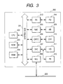
- Fig. 3 is a schematic diagram illustrating the internal arrangement of a common personal computer. Basically, the desktop PC 111, the notebook PC 113 and the server terminal 112 in Fig. 2 all have the internal arrangement shown in Fig. 3.
- a PC 200 executes client terminal software or network server terminal software (usually referred to, hereinafter, as network device terminal search software), and is the equivalent of one of the devices 111, 112 and 113 in Fig. 2.
- the PC 200 includes a CPU 202, which executes the network device terminal search software that is stored, in a ROM 203 or on a hard disk (HD) 211, or that is supplied by a floppy disk controller (FD) 212.
- the PC 200 controls the device terminals that collectively are connected to a system bus 201.
- a RAM 204 functions as a main memory and a work area for the CPU 202.
- a keyboard controller (KB) 205 controls the entry of instructions at a keyboard (KB) 209.
- a CRT controller (CRTC) 206 controls the display screen of a CRT display (CRT) 210.
- a disk controller (DKC) 207 controls the accessing of a hard disk (HD) 211, on which a boot program, various applications, an editing file, a user file and a network management program are stored, and the floppy disk controller (FD) 212.
- HD hard disk
- FD floppy disk controller
- a network interface card (NIC) 208 is used to exchange data, via a LAN 220, with network printers, other network devices, or PCs.
- a pointing device controller (PDC) 213 controls a pointing device (PD) 214 and the LAN 220 corresponds to the LAN 100 in Fig. 2.
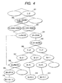
- the hierarchical-type location information is so constituted that the location information for a client terminal and a device terminal has a hierarchical structure, and so that a hierarchical class can be designated in accordance with the intent of a user.
- the map is represented as "10X+10Y" (310).”
- C represents the name of a country (JP denotes Japan, US denotes the United States, etc.), "0" represents the name of an organization (ABC Trading Company, XYZ Products, etc.), "BR” represents the name of a branch or a subdivision (Tokyo branch, Osaka branch, etc.), "OP” represents the presence of optional information (extended), "BU” represents the name of a building (AA Building, BB Building, etc.), "FL” denotes a floor number (1F, 2F, etc.), “BL” denotes a block on a floor (101, 201, etc.), “DV” denotes the attribute of a client terminal or a device terminal (a printer, MFP, PC, etc.), and "NM” denotes the name of a device terminal (LBP 1110, LBP 3310, etc.).
- the attribute of each entry has a value that falls within a predetermined range (value).
- the location information for each device terminal that is connected to the network is managed by using a hierarchical structure.
- a hierarchical structure the location of a device terminal that is requested for the performance of a search and that corresponds to a user's intent is appropriately specified, and the location of the pertinent device terminal can be displayed so that the user can easily identify it.
- the hierarchical structure is not limited to that in Fig. 4, and various other structures can be employed.
- Fig. 5 is a diagram showing a location map for the block 2-1 on the 2F.
- the layout such as the actual arrangement of desks and the partitions on that floor, is provided in advance as a bit map, and the color printer 101, the MFP 102, the firewall 120 and the server terminal 112 are represented at locations on the layout, as is shown in Fig. 5.
- Fig. 6 is a diagram showing a bit map for the block 2-2 on floor 2F.
- the PC 111 and the printer 103 are positioned as is shown in Fig. 6.
- Fig. 7 is a diagram showing a bit map for the block 1-1 on floor 1F.
- the PC 113 and in the layout the monotone printer 104 are located as is shown in Fig. 7.
- Fig. 8 is a diagram showing a bit map for the block 1-2 on floor 1F.
- the scanner 105 is positioned as is shown in Fig. 8. As will be described later, this bit map is displayed on the screen of the client terminal of a user.
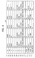
- Fig. 9 is a diagram showing the hierarchical-type location information and the attribute information for each device terminal that is managed by the server terminal 112. As is shown in Fig. 9, in this embodiment a total of five device terminals are managed, and for each device terminal, management is provided for each of the hierarchical-type location information items 802 to 810. Further, in this embodiment, a color attribute 811, which represents the pertinent device terminal, can input and output color data, an IP address 812, which is the network address of the terminal device, and a charge attribute 813, which represents charge information, are managed as attribute information of the device terminal.
- the users of the client terminals are sorted into regular users and guest users, and information 814 indicates whether a guest user can employ a corresponding device. It should be noted that a regular user can employ all the devices.
- each column in Fig. 9 corresponds to a tuple, which is data for one case concerning the registered device, and each row corresponds to an attribute for each tuple.
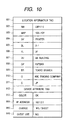
- Fig. 10 is a diagram showing the hierarchical-type location information and device terminal attribute information that is registered as is shown in Fig. 9.
- the location information 902 to 911 and the attribute information 913, 914 and 915 are transmitted to the server, after the tab (TAG).
- TAG tab
- the device terminals are powered on they, not the server terminal 112, register this information.
- the server terminal 112 manages the received information by using the table 800 in Fig. 9, and upon the receipt of a request from a client terminal, transmits a response to the client terminal.
- a hierarchical-type location information TAG 901 is used to indicate that the information 902 to 911 that follows is hierarchical-type location information.
- a device terminal attribute information TAG 912 indicates that the following information 913 to 916 represents the attribute of the device terminal. That is, the information 913 indicates the Color attribute is OK, i.e., that color printing is available; the information 914 indicates that the IP address is 192.1.2.1; the information 915 indicates that printing per sheet charges are five yen; and the information 916 indicates that guest user employment is not permitted.
- Fig. 11 is a diagram showing the hierarchical-type location information and the client attribute information for the client terminal.
- Location information 702 to 711 and client attribute information 713 are transmitted to a server after the transmission of individual tags (TAGS).
- TGS individual tags
- the information is transmitted to the server 112 when the device terminal search request is issued.
- information 713 represents the attribute of a user of the client terminal, and "guest" represents a guest user.
- guest represents a guest user.
- information as to whether the user of a client terminal is a regular user or a guest user is stored in advance in the client terminal. Therefore, for a guest user, the user must release to the guest user the client terminal that is set up.
- Fig. 12 is a diagram showing a search condition input screen when a search is conducted by the client terminals 111 to 113.
- search data are input by the entries 1001a, 1001b and 1001c.
- a pull-down menu can be provided to select the search data.
- Attribute information corresponding to each entry is input as part of the entries 1002a, 1002b and 1002c.
- the start level whereat the search results obtained under the search conditions are to be displayed is entered in an entry 1006.
- the attribute information for a printer, an MFP or a scanner is displayed on a pull-down menu, and the desired attribute information is selected by a user.
- the search state is entered by using input buttons 1003 and 1004, with an AND condition being employed for the button 1003 and an OR condition being employed for the button 1004.
- the user enters a display start level in the entry 1006, in order to set the start level whereat results that are to be obtained under the search condition are displayed, and depresses a search start button 1005 to initiate the execution of the search.
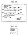
- Fig. 13 is a diagram showing an example search entry.
- a device terminal which is a printer for which attribute information is provided and which can enable color output, is searched for.
- "floor" is input as part of the entry 1001c
- "2F” is input as part of the entry 1002c.
- "floor" is input as part of the entry 1006.
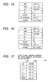
- Fig. 14 is a diagram showing expressions that represent the search condition for the above example, wherein the device terminal (DV) is a printer installed on the second (2F) floor (FL) for which (OK) color output (color) can be enabled.
- the device terminal (DV) is a printer installed on the second (2F) floor (FL) for which (OK) color output (color) can be enabled.
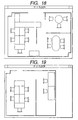
- Fig. 15 is a diagram showing an example wherein the client terminal 111 requests the server terminal 112 to search for a device terminal, under the search condition shown in Fig. 14, and the server terminal 112 returns, to the client terminal PC 111, information concerning the device terminal that matches the search condition.
- the server terminal 112 searches the information table 800 (Fig. 9) that is held in the server terminal 112 under the search conditions listed in Fig. 14, which are received from the client terminal 111, and returns, to the client terminal 111, information concerning the device terminal that matches the search conditions provided with the hierarchical-type location information.
- the server terminal 112 since only the device terminal that matches the search conditions in Fig. 14 is LBP 1110, the information shown in Fig. 15 is returned to the client terminal 111. Furthermore, since the device terminal LBP 1110 is located on the same floor as the client terminal 111, the server terminal 112 returns to the client terminal 111 the hierarchical-type location information entered below the block (BL) of the device terminal LBP 1110.
- Fig. 16 is a diagram showing an example wherein the server terminal 112 returns, to the client terminal PC 113, information for the device terminal that matches the search conditions shown in Fig. 14.
- the server terminal 112 since the device terminal LBP 1110 that matches the search condition is located in the same building as the client terminal 113, the server terminal 112 returns, to the client terminal PC 113, the hierarchical-type location information entered below the floor (FL) of the device terminal LBP 1110.
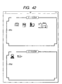
- Fig. 17 is a diagram showing information for a layout map held by the client terminals 111 and 113.
- the client terminals 111 and 113 can display the layout map for a device terminal 1401 that has hierarchical-type location information.
- layout map information 1403 is included for each block (BL) 1402.
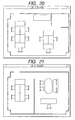
- a layout bit map shown in Fig. 18 is held for BL 1-1
- a layout bit map shown in Fig. 19 is held for BL 1-2
- a layout bit map shown in Fig. 20 is held for BL 2-1
- a layout bit map shown in Fig. 21 is held for BL 2-2
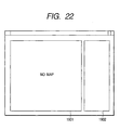
- a layout bit map shown in Fig. 22 is displayed when there is no attribute value.
- Figs. 18 to 21 are the layout bit map diagrams for the individual blocks.
- information representing the device terminal that is searched for is superimposed on a layout bit map, so that the floor, the block and the position in the block at which the device terminal, for which a search is requested, is located can be clearly indicated.
- Fig. 22 is a diagram showing an unknownMAP that is displayed when the device terminal does not hold the hierarchical-type location information, or when the layout bit map of the client terminal is not matched.
- the absence of map information is shown in an area 1901, and a device terminal that does not hold the hierarchical-type location information or that includes unmatched hierarchical-type location information is displayed in an area 1902.
- Fig. 23 is a diagram showing bit map information for each device terminal held by the client terminal 111 or 113.
- the bit map information is correlated for each device terminal name (NM), and for an unknown device terminal name, a bit map labeled "unknown" is displayed.
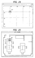
- Fig. 24 is a diagram showing the location of a device terminal bit map that has been superimposed on a layout map.
- the color printer 101 (LBP 1110), for which the hierarchical-type map location information "10X+10Y" applies, is displayed at the position shown in Fig. 24.
- the display bit map and the layout bit map are displayed together, the location of a device terminal for which a search has been requested can be shown so that it can be easily identified by a user.
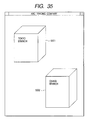
- Fig. 25 is a diagram showing an example bit map that is displayed by the client terminals 111 and 113 following a search. Based on the search results that are returned by the server terminal 112, and the start level for the display of the search results that is designated in the entry 1006 in Fig. 13, the block (2F-1) map is displayed, and on the map the device terminal LBP 1110 is displayed. From this display, it is apparent that the color printer 101 is located on the table near the door in the block 2-1 on the second floor.
- Fig. 26 is a block diagram illustrating the internal arrangement of the color printer 101 (LBP 1110) in this embodiment. As is shown in Fig. 26, the color printer 101 is so designed that a CPU 2302 for processing a program, a ROM 2303 in which the program is stored, and a RAM 2304 that serves as a work area and a buffer area for the program are connected to a system bus 2301.
- An engine 2309 is also connected, via an LBP engine controller 2305, to the system bus 2301, and a panel controller 2306 controls the input/output to a panel 2310 and manages the panel 2310.
- the color printer 101 (LBP 1110) a hard disk (HD) 2311, on which print data can be temporarily spooled.
- a disk controller 2307 manages the HD 2311.
- a network interface controller 2308 is used to connect the printer 101 to a network.
- Nonvolatile RAM (NVRAM) 2312 is used to hold data even when the power supply to the printer 101 is cut off, and in this embodiment, both the hierarchical-type location information and the attribute information are stored in the NVRAM 2312. This information may also be stored on the HD 2311, instead of in the NVRAM 2312.
- Figs. 27 to 31 are flowcharts used for explaining the processing performed for this embodiment, and will now be referred to while a detailed description of the processing is presented.
- the processing described below for the individual apparatuses is performed when the CPUs in these apparatuses execute programs that are stored using such memory devices as ROMs and hard disks.
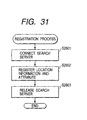
- the processing performed to register the hierarchical-type location information for a device terminal will be described while referring to the flowchart in Fig. 31.
- the color printer 101 LBP 1110 is employed as an example.
- the LBP 1110 stores hierarchical-type location information and attribute information in the nonvolatile RAM 2312, which is the self-position holding device in the device terminal.
- the CPU 2302 is connected to the server terminal 112 (step S2801), and after the connection is established, the LBP 1110 reads the hierarchical-type location information and the attribute information from the nonvolatile RAM 2312 and transmits it to the server terminal 112.
- the server terminal 112 uses the form shown in Fig. 10 to register the hierarchical-type location information and the attribute information, for the LBP 1110, in the management device 11 (step S2802).
- the CPU 2302 of the LBP 1110 is disconnected from the server terminal 112 (step S2803).
- the individual device terminals can register their hierarchical-type location information and attribute information.
- the server terminal 112 is constituted by an event-driving program, and when an event occurs, the server terminal 112 analyzes it and performs a corresponding process.
- the server terminal 112 When the server terminal 112 is powered on, first, the server terminal 112 opens a reception port (step S2401). The server terminal 112 then acquires an event (step S2402), and determines whether the acquired event is an end command (step S2403). When the acquired event is an end command, the server terminal 112 closes the reception port (step S2404), and terminates the processing.
- the server terminal 112 determines whether the acquired event is a search request (step S2405).
- the server terminal 112 performs a database search, which will be described later.
- step S2407 the server terminal 112 determines whether the event is a registration request for submission to the database. If the event is a registration request, the server terminal 112 registers the received data in the table 800 in Fig. 9 (step S2408), following which the registered data are stored on the HD 211. When at step S2407 the event is another request, the server terminal 112 performs the other process (step S2409).
- step S2501 a check is performed to determine whether the processing for all the search conditions has been performed. This processing is repeated until all the search conditions have been satisfied.
- step S2501 When, at step S2501, all the search conditions in a packet have been satisfied, the results are transmitted to the client terminal that requested the search (step S2502).
- step S2503 whereat the search conditions (Fig. 14) are extracted from a received packet. Then, to satisfy the search conditions, a check is performed to determine whether a search has been conducted for all the registered device terminal information in the table in Fig. 9 (step S2504). To perform such a search, the location information for the client terminal that requested the search is obtained from the received packet, and based on this location information, and in consonance with the included search conditions, a search performed within an optimal range is conducted. For example, when the search conditions in Figs. 13 and 14 are transmitted to the server terminal 112 by the client terminal 111 in Fig. 2, a search of the second floor of the AA Building of the Tokyo Branch of the ABC Trading Company is performed because the client terminal 111 is located in the AA Building.
- step S2504 when at step S2504 it is determined that a search for all the registered device terminal information is to be performed, program control returns to step S2501 to extract the next search condition.
- step S2504 program control advances to step S2505, and the n-th device information is extracted from the HD 211. Then, a check is performed to determine whether the extracted device terminal information matches the search condition (step S2506).
- step S2507 When the device terminal information matches a condition, that information is obtained (step S2507) and at step S2508 the location information for the client terminal that requested the search is obtained from the received packet. Then, the location information is extracted for a device terminal having a rank that is lower than that which matches the location information for the client terminal and the location information for the device terminal that is found (step S2509), and is added to the search results (step S2510).
- the user of the client terminal is a guest user, only a device in the attribute table 800 in Fig. 9 that the guest user can employ is added.
- step S2506 When, at step S2506, the device terminal information does not match the search condition, program control returns to step S2504 to perform the processing for the next device. In this manner, a search of all the device terminals in the table 800 in Fig. 9 is performed in accordance with individual search conditions, and the search results are transmitted to the client terminal.
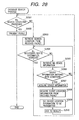
- the client terminal 111 or 113 is constituted by an event-driving program. When an event has occurred, the client terminal 111 or 113 analyzes the event and performs a corresponding process.
- step S2601 the client terminal 111 or 113 acquires an event. And when an end command event is acquired, the processing is terminated (step S2602).
- a user enters a search condition on the search condition input screen shown in Fig. 12. Then, when the user clicks on the search start button 1005, a search command request is issued.
- the client terminal 111 or 113 transmits, to the server terminal 112, hierarchial-type location information for the client terminal 111 or 113 (steps S2604 and S2608).
- the search condition is then included in the search request that is to be transmitted.
- the client terminal 111 or 113 issues an inquiry to the server terminal with the search condition expression in Figs. 13 and 14.
- the search expression is stored on the HD 211, this can be employed for the next search, so that the user does not have to re-enter the search condition.
- step S2605 a check is performed to determine whether the search results are received, and when at step S2605 the search results shown in Fig. 15 are received, at step S2609, the start level, input as part of the entry 1006 in Fig, 13, for the display of the search results is acquired, and the search results are displayed in accordance with that display start level (step S2606). When another event is received, the other process is performed (step S2607).
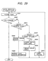
- step S2701 a check is performed to determine whether all the search results have been processed. When all the processes have been completed, the display processing is terminated.
- step S2701 When at step S2701 all the processes have not been completed, program control advances to step S2702, and the hierarchical-type location information is obtained from the received search results. Based on the obtained hierarchical-type location information, a check is performed to determine whether the client terminal can display the map for that information (step S2703).
- the hierarchical-type location information with which the device terminal can be displayed includes the information 1401 in Fig. 17. If the hierarchical-type location information does not include the information 1401, a check is performed to determine whether the unknownMAP has been displayed (step S2709). If the unknownMAP has not yet been displayed, it is displayed in Fig. 22 (step S2710).
- the NM information is obtained from the hierarchical-type location information (step S2711), and the device terminal bit map that corresponds to the NM is read from the table in Fig. 23 and displayed in the area 1902 (step S2712). In other words, the device terminal is displayed for which the hierarchical-type location information has not yet been registered.
- the client terminal 111 or 113 compares the BL information with the BL information table in Fig. 17.
- step S2705 If, at step S2705, the corresponding layout bit map has been displayed, program control advances to step S2707.
- the device terminal bit map is read from the table in Fig. 23. Further, based on the map information, the location is determined for the device terminal bit map that is to be displayed.
- the device terminal bit map for the LBP 1110, as the NM is located at the position "10X+10Y" on the map that is displayed at step S2706. Since the device terminal bit map is located at the position shown in Fig. 24, the search results shown in Fig. 25 can be displayed (step S2708).
- the five layout bit maps which, for the individual blocks, are bit maps 1-1, 1-2, 2-1 and 2-2 and the "unknown" bit map, have been employed.
- an explanation will be given for a display method employed by a client when a layout bit map is provided for each rank. This display method includes the display method that was previously described.
- Fig. 33 is a diagram showing a MAP list that corresponds to each rank that is to be searched for.
- the lower half-list in Fig. 33 corresponds to the list in Fig. 17.
- the device map is displayed based on the attribute information immediately below the attribute for the rank that is to be searched for.
- the hierarchical relationship of the ranks in Fig. 4 should be referred to.
- the user selects the company name (0) in the entry 1001a from the pull down menu, enters the ABC Trading Company as the attribute value 1002a, and clicks on the search start button 1005.
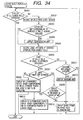
- the client obtains from the server the search results provided by the processing explained above, and based on these search results, the client displays the device bit map on the layout bit map.
- step S6001 when the processing is initiated, at step S6001, first a check is performed to determine whether all the search results have been displayed, and if they haven't, the display processing is repeated until all the results have been displayed.
- step S6002 the attribute NM is obtained from the search results to display the device bit map at steps S6008, S6010 and S6013.
- step 6003 a check is performed to determine whether the layout bit map that corresponds to the attribute for the search condition has been displayed.
- the layout bit map has not yet been displayed, at step S6004 the layout bit map is displayed and program control advances to step S6005.
- step S6005 an attribute lower than the attribute to be searched for and the attribute value are extracted from the search results, and at step S6006, a check is performed to determine whether the obtained attribute value can be displayed. If it is assumed that a device whose attribute value falls outside the range, and a device whose attribute value has not been entered can not be displayed, program control shifts to step S6011.
- step S6011 a check is performed to determine whether the unknownMAP has been displayed. If the unknownMAP has not yet been displayed, at step S6012 it is displayed, and superimposed on its device column is the device bit map that corresponds to the NM value obtained at step S6002 (step S6013).
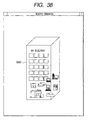
- step S6006 When, at step S6006, the attribute value can be displayed, a check is performed to determine whether the lower attribute is a MAP attribute (step S6007). If the lower attribute is not a MAP attribute, program control advances to step S6008, and the device bit map that corresponds to the NM value obtained at step S6002 is superimposed on it at the attribute position for the layout bit map on the display. In this case, since the attribute value for the rank BR below (0) is the Tokyo branch, according to the hierarchical-type location information (see Fig. 4), each device is displayed at the location of the Tokyo branch 5001. As a result, the display in Fig. 36 is acquired.
- the user selects the block name (BL) in the entry 1001a, selects 2-1 as the attribute value 1002a, and clicks on the search start button 1005.
- the client acquires the search results from the server, and based on these search results, the client displays the device bit map on the layout bit map.
- the processing in Fig. 34 is also performed, and in this case, since at step S6007 the lower attribute information is MAP information, program control advances to step S6009.
- a check is performed to determine whether the range represented by the coordinates for the NM value obtained at S6002 lies within the limits of the layout bit map. If it does, at step S6010 the device bit map that corresponds to the NM value obtained at step S6002 is superimposed on the layout bit map display at the position designated by the coordinate values.
- attribute 0 attribute value ABC Trading Company.
- the attribute below the attribute value BR is OP, which indicates the presence of OPTION and the presence of detailed information at a lower rank.
- a device whose attribute BU is the AA Building is displayed in an area 5201.
- a device whose attribute FL, below the attribute BU, is 2F is displayed in a bit map 5402, and a device whose attribute FL is 1F is displayed in a bit map 5401.
- a device whose attribute BL, below the attribute FL, is 2-1 is displayed in a bit map 5601, and a device whose attribute BL is 2-2 is displayed in a bit map 5602.
- the devices whose attribute BL, below the attribute FL, is 1-2 are displayed in a bit map 5901, and the device whose attribute BL is 1-1 is displayed in a bit map 5902.
- the search can be conducted in accordance with a search level requested by a user, and the search results can be roughly displayed in detail in accordance with the hierarchical location of the information that is obtained.
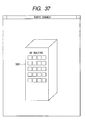
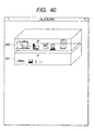
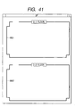
- the client terminal stores layout bit maps in Figs. 18 to 21, 35, 37, 39, 41 and 43.
- the server terminal stores these layout bit maps.
- Fig. 45 is a diagram showing the arrangement of a device search system according to this embodiment.
- a server terminal 451 in Fig. 45 includes a map information holding device 4511 that, in addition to the layout bit maps in Figs. 18 to 21, 35, 37, 39, 41 and 43, stores layout maps for the individual ranks of the overall system, and a memory 4512 in which bit map data representing a device terminals are stored.
- a client terminal 452 is designed by removing the map data holding device 21, the second display device 25 and the memory 25a from the arrangement for the client terminal 20 in Fig. 1.
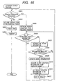
- Fig. 46 is a flowchart for explaining the search processing performed by the server terminal 451 according to this embodiment.
- the client terminal 452 when the client terminal 452 transmits a search request to the server terminal 431, the client also transmits the information that represents the start level (1006 in Fig. 13) that is designated by the client terminal 452 for the display of the search results.
- step S4601 a check is performed to determine whether processing has been completed to satisfy all the search conditions. This processing is to be repeated until all the search conditions have been satisfied.
- a search condition (Fig. 14) is extracted from a received packet. Then, a check is performed to determine whether under the search condition all the registered device terminal information has been searched for in the table in Fig. 9 (step S4606). When all the registered device terminal information has been searched for, program control returns to step S4601 to extract the next search condition.
- step S4606 When, at step S4606, a search for all the registered device terminal information has been not been completed, the n-th device information is extracted from the HD 211 (step S4607). Then, a check is performed to determine whether extracted device terminal information matches the search condition (step S4608). When the extracted device terminal information matches the condition, information to that effect is obtained (step S4609), and at step S4610 location information for the client terminal 452 that requested the search is obtained from the received packet. Then, location information is extracted for a device terminal lower than the rank that matches the location information for the client terminal 452, and location information for a device terminal that is found (step S4611) is added to the search results (step S4610).
- step S4601 When, at step S4601, the search has been completed for all the search conditions, information indicating the start level that the client terminal 452 designated for the display of the search results is obtained from the received packet (step S4602). Then, the layout map for the rank that matches the display start level is selected from the map information holding device 4511. In addition, based on the device terminal information obtained as a result of the search, necessary bit map data (bit map data that represent the device terminal) is selected from the memory 4512. Following this, the bit map data are synthesized with the selected layout bit map to create a map for transmission to the client terminal. Subsequently, the hierarchical-type location information for the device terminal obtained as a result of the search is employed for the synthesization of bit map data, and the map prepared at step S4603 is transmitted to the client terminal 452 (step S4604).
- bit map data bit map data that represent the device terminal
- the server terminal 451 of this embodiment searches for the device terminals in accordance with search conditions that are designated by the client terminal 452. And when the server terminal 451 provides the results of the search to the client terminal 452, it prepares a map that matches the display start level for the client terminal 452 and transmits the map to the client terminal 452.
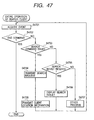
- Fig. 47 is a flowchart for explaining the processing performed by the client terminal 452 according to the embodiment.
- the client terminal 452 is constituted by an event-driven program. When an event occurs, the client terminal 452 analyzes the event and performs a corresponding process.
- step S4701 the client terminal 452 acquires an event.
- the processing is terminated (step S4702).
- a user can enter a search condition that is displayed on the search condition input screen shown in Fig. 12, and then, when the user clicks on the search start button 1005, a command event occurs requesting that a search command be issued.
- the client terminal 452 transmits a search request to the server terminal 451 (step S4704).
- the search request includes the search condition designated by the user and the information indicating the start level for the display of the search results. Further, in addition to the search request, hierarchial-type location information for the client terminal 452 is also transmitted (step S4708).
- step S4704 After the client terminal 452 has transmitted the information at steps S4704 and S4708, it waits to receive the search results from the server terminal 451. Then, at step S4704 a check is performed to determine whether the search results have been received. And when it is determined at step S4705 that the result of the search at step S4604 in Fig. 46, i.e., the map, has been received, at step S4706 the received map is displayed on the display unit 27 by the first display device 24. If, however, at step S4705 another event is received, another process is performed (step S4707).
- the server terminal since the server terminal prepares a map that matches the display start level of the client terminal and transmits it to the client terminal, the processing load imposed on the client terminal can be reduced.
- a device terminal to be employed and the range for the hierarchical location that is to be searched can be limited for each user ID that is employed by users to log in at a client terminal.
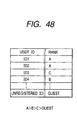
- the server terminal 112 in this embodiment stores a table in Fig. 48 that represents the rank assigned to each user ID, a table in Fig. 49 that represents the rank of a user ID for which the employment of (the search for) each device terminal is permitted, and a table in Fig. 50 that indicates the hierarchical-type location information that can be searched for by each user ID rank.
- Fig. 48 user IDs ID1 and ID2 belong to rank A, user ID3 belongs to rank C, and user ID4 belongs to rank B. Other user IDs that are not registered in this table are regarded as guest users.
- the values of the rights accorded the user ID ranks are rank A > rank B > rank C > guests.
- the LBP 1110 can be employed by users whose user IDs are ranked equal to or higher than B, i.e., those ranked A and B, and the MFP 6550 can be employed by users whose user IDs are ranked equal to or higher than C, i.e., those ranked A, B and C.
- the LBP 3310 which is located in the block 2-2 on the second floor (2F) of the AA Building at the Tokyo branch of the ABC Trading company, can be employed by users whose user IDs are ranked equal to or higher than A, i.e., those ranked A
- the LBP 3310 which is located in the block 1-1 on the first floor (1F) of the AA Building at the Tokyo branch of the ABC Trading company, can be employed by users whose user IDs are ranked equal to or higher than that of guest, i.e., those ranked A, B, C and guest.
- the SCN 2160 can be employed by users whose user IDs are ranked equal to or higher than C, i.e., those ranked A, B and C.
- the client terminal when logging in at a client terminal, the user enters his or her user ID and the client terminal stores the user ID. Then, when at step S2604 in Fig. 29 the client terminal transmits a search request to a server terminal, the client terminal also transmits the user ID stored in the owner location 713 in Fig. 11.
- the server terminal determines the rank of the user in accordance with the user ID it received, and conducts a search based on the obtained rank. That is, during the search process in Fig. 28, the server terminal performs a search within the hierarchical location search range authorized for the rank of the user ID received from the client terminal, and transmits the search results to the client terminal.
- the above embodiments may be applied to a system constituted by a plurality of apparatuses (e.g., a host computer, an interface device, a reader and a printer) or to a single apparatus.
- apparatuses e.g., a host computer, an interface device, a reader and a printer
- the device terminal control program on the network may be executed by a PC 200 while it employs an externally installed program.
- the program may be loaded into the PC 200 by reading it from a storage medium, such as a CD-ROM, a flash memory or a floppy disk, or for e-mail or PC communications, it may be read from an external storage medium and transmitted across a network.
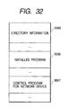
- Fig. 32 is a diagram showing a memory map for a CD-ROM that constitutes an example storage medium.
- directory information is stored in an area 9999, and represents an area 9998, in which an installation program is stored, and an area 9997, in which a network device terminal control program is stored.
- the area 9998 is used to store the installation program, while the area 9997 is used to store the network device terminal control program.
- the installation program in the area 9997 is loaded into the system and is executed by the CPU 202.
- the installation program executed by the CPU 202 reads the network device terminal control program from the area 9997, and stores it on the hard disk 211.
- the functions in the previous embodiments can be performed when program code is read and executed by the computer, instead the functions can be performed in accordance with an instruction in the program code, in an OS (Operating System) running on the computer or in another application software program the computer interacts with program code to accomplish the functions of the above embodiments.
- OS Operating System
- embodiments include: a case wherein program code, read from a storage medium, is written in a memory that is mounted on a function expansion board inserted into a computer, or on a function expansion unit connected to a computer, and in consonance with a program code instruction, a CPU mounted on the function expansion board or in the function expansion unit performs one part, or all, of the actual processing in order to implement the functions in the above described embodiments.
- the device terminals can be searched for based on the hierarchical-type location information that hierarchically represents the locations of the device terminals. Further, the search results can be displayed based on the locations of the device terminals. Therefore, the client terminal can obtain hierarchical-type location information for the device terminals that matches the search conditions designated by a user, and can also display the information on the layout map. Thus, the user can easily understand the hierarchical locations of the individual device terminals.
- the search results for the device terminals are restricted, so that the amount of search result data that must be transmitted by the server terminal can be minimized. Accordingly, the traffic on a network system and the time required to display search results can be reduced, and the results desired by the a can be rapidly and precisely provided.
- Embodiments can be implemented by a computer program operating on a standard desk top computer.
- An embodiment therefore comprises a storage medium storing processor implementable instructions for controlling a processor to carry out the method as hereinabove described.
- the computer program can be obtained in electronic form for example by downloading the code over a network such as the internet.
- another embodiment comprises an electrical signal carrying processor implementable instructions for controlling a processor to carry out the method as hereinbefore described.
Landscapes
- Engineering & Computer Science (AREA)
- Computer Networks & Wireless Communication (AREA)
- Signal Processing (AREA)
- Human Computer Interaction (AREA)
- Computer And Data Communications (AREA)
- Information Retrieval, Db Structures And Fs Structures Therefor (AREA)
- User Interface Of Digital Computer (AREA)
Claims (10)
- Appareil (10, 451) pour traiter des données afin d'effectuer une recherche en conformité avec des instructions d'un utilisateur pour identifier des dispositifs (20, 30, 452) d'une pluralité de dispositifs connectés à un réseau (40), l'appareil comprenant :caractérisé par :un moyen de stockage (lla) conçu pour stocker des données définissant les positions hiérarchiques (802, 804-810) de la pluralité de dispositifs (20, 30, 452) connectés au réseau (40) ;un moyen (12) pour recevoir une demande de recherche (figure 14, S2405) de l'un de la pluralité de dispositifs (20, 452) connectés au réseau en définissant des paramètres de recherche définis par l'utilisateur comprenant une position définie par l'utilisateur (1001c, 1002c) pour effectuer la recherche afin d'identifier des dispositifs de la pluralité de dispositifs à la position définie par l'utilisateur ;un moyen (15) pour acquérir des données définissant la position hiérarchique de l'un de la pluralité de dispositifs d'où a été reçue la demande de recherche (52508, S4610) ;un moyen (13) pour rechercher les données définissant les positions hiérarchiques de la pluralité de dispositifs, stockées dans le moyen de stockage et pour générer des résultats de recherche en conformité avec la position définie par l'utilisateur et avec la position hiérarchique de l'un de la pluralité de dispositifs d'où a été reçue la demande de recherche (S2509, S2510, S4611, 54612) ; etun moyen (14) pour envoyer les résultats de recherche à l'un de la pluralité de dispositifs d'où a été reçue la demande de recherche (52502, S4604).
- Appareil selon la revendication 1, dans lequel le moyen (13) pour rechercher les données définissant les positions hiérarchiques de la pluralité de dispositifs, stockées dans le moyen de stockage et pour générer des résultats de recherche a pour fonction d'identifier chaque dispositif de la pluralité de dispositifs connectés au réseau, qui a une position à la fois dans un premier domaine de positions défini par la position définie par l'utilisateur dans la demande de recherche ainsi que dans un second domaine de positions défini par la position hiérarchique de l'un de la pluralité de dispositifs d'où a été reçue la demande de recherche (figure 5, figure 6).
- Appareil selon la revendication 1 ou 2, dans lequel :le moyen de recherche des données définissant les positions hiérarchiques de la pluralité de dispositifs, stockées dans le moyen de stockage et pour générer des résultats de recherche a pour fonction de générer des résultats de recherche définissant une pluralité de positions hiérarchiques (figure 15, figure 16).
- Appareil selon l'une quelconque des revendications précédentes, comprenant en outre :un moyen (4511) pour stocker des données de cartes définissant une pluralité de cartes (figures 35, 37, 39, 41) illustrant les positions hiérarchiques des dispo-sitifs ; etun moyen pour sélectionner l'une de la pluralité de cartes (S4603) ;et dans lequel le moyen pour envoyer les résultats de recherche a pour fonction d'envoyer des données définissant l'un de la pluralité de dispositifs définissant l'une, sélectionnée, de la pluralité de cartes ainsi que les résultats de recherche de l'un de la pluralité de dispositifs d'où a été reçue la demande de recherche (S4604).
- Procédé de traitement de données pour effectuer une recherche en conformité avec des instructions d'un utilisateur pour identifier des dispositifs d'une pluralité de dispositifs (20, 30, 452) connectés à un réseau (40), le procédé comprenant :caractérisé par :le stockage de données définissant les positions hiérarchiques (802, 804-810) de la pluralité de dispositifs (20, 30, 452) connectés au réseau (40) ;la réception d'une demande de recherche (figure 14, S2405) de l'un d'une pluralité de dispositifs (20, 452) connectés au réseau définissant des paramètres de recherche définis par l'utilisateur comprenant une position définie par l'utilisateur pour effectuer la recherche afin d'identifier des dispositifs de la pluralité de dispositifs à la position définie par l'utilisateur ;l'acquisition de données définissant la position hiérarchique de l'un de la pluralité de dispositifs d'où a été reçue la demande de recherche (52508, S4610) ;la recherche des données stockées définissant les positions hiérarchiques de la pluralité de dispositifs stockés et la production de résultats de recherche en conformité avec la position définie par l'utilisateur et la position hiérarchique de l'un de la pluralité de dispositifs d'où a été reçue la demande de recherche (S2509, S2510, S4611, S4612) ; etl'envoi des résultats de recherche à l'un de la pluralité de dispositifs d'où a été reçue la demande de recherche (S2502, S4604).
- Procédé selon la revendication 5, dans lequel l'étape de recherche des données stockées définissant les positions hiérarchiques de la pluralité de dispositifs et produisant des résultats de recherche identifie chaque dispositif de la pluralité de dispositifs connectés au réseau, qui a une position à la fois dans un premier domaine de positions défini par la position définie par l'utilisateur dans la demande de recherche ainsi que dans un second domaine de positions défini par la position hiérarchique de l'un de la pluralité de dispositifs d'où a été reçue la demande de recherche (figure 5, figure 6).
- Procédé selon la revendication 5 ou 6, dans lequel :l'étape de recherche des données stockées définissant les positions hiérarchiques de la pluralité de dispositifs et produisant des résultats de recherche, produit des résultats définissant une pluralité de positions hiérarchiques (figure 15, figure 16).
- Procédé selon l'une quelconque des revendications 5 à 7, comprenant en outre :le stockage de données de cartes définissant une pluralité de cartes (figures 35, 37, 39, 41) illustrant les positions hiérarchiques de la pluralité de dispositifs ; etla sélection de l'une de la pluralité de cartes (S4603) ;et dans lequel l'étape d'envoi des résultats de recherche comprend l'envoi de données définissant l'une, sélectionnée, de la pluralité de cartes ainsi que les résultats de recherche à l'un de la pluralité de dispositifs d'où a été reçue la demande de recherche (S4604).
- Support de stockage stockant des instructions d'un programme informatique pour programmer un appareil de traitement programmable afin de le configurer en tant qu'appareil tel que défini dans au moins l'une des revendications 1 à 4.
- Signal transportant des instructions de programmation pour programmer un appareil de traitement programmable afin de le configurer en tant qu'appareil tel que défini dans au moins l'une des revendications 1 à 4.
Applications Claiming Priority (4)
| Application Number | Priority Date | Filing Date | Title |
|---|---|---|---|
| JP21808299 | 1999-07-30 | ||
| JP21808299 | 1999-07-30 | ||
| JP2000204754 | 2000-07-06 | ||
| JP2000204754A JP2001109780A (ja) | 1999-07-30 | 2000-07-06 | 情報処理装置、情報処理システム、情報処理装置の制御方法及び記憶媒体 |
Publications (3)
| Publication Number | Publication Date |
|---|---|
| EP1073234A2 EP1073234A2 (fr) | 2001-01-31 |
| EP1073234A3 EP1073234A3 (fr) | 2002-07-31 |
| EP1073234B1 true EP1073234B1 (fr) | 2005-04-06 |
Family
ID=26522383
Family Applications (1)
| Application Number | Title | Priority Date | Filing Date |
|---|---|---|---|
| EP00306335A Expired - Lifetime EP1073234B1 (fr) | 1999-07-30 | 2000-07-25 | Système et dispositif pour rechercher des appareils reliés à un réseau |
Country Status (5)
| Country | Link |
|---|---|
| US (2) | US6996611B1 (fr) |
| EP (1) | EP1073234B1 (fr) |
| JP (1) | JP2001109780A (fr) |
| CN (1) | CN1196070C (fr) |
| DE (1) | DE60019209T2 (fr) |
Families Citing this family (44)
| Publication number | Priority date | Publication date | Assignee | Title |
|---|---|---|---|---|
| US7032186B1 (en) * | 2001-09-28 | 2006-04-18 | Emc Corporation | Methods and apparatus for representing resources in a computing system environment |
| US7499986B2 (en) * | 2001-10-04 | 2009-03-03 | International Business Machines Corporation | Storage area network methods with event notification conflict resolution |
| US20030093509A1 (en) * | 2001-10-05 | 2003-05-15 | Li Raymond M. | Storage area network methods and apparatus with coordinated updating of topology representation |
| US20040073609A1 (en) * | 2002-07-03 | 2004-04-15 | Brother Kogyo Kabushiki Kaisha | Information output system |
| JP2004288066A (ja) * | 2003-03-24 | 2004-10-14 | Fuji Xerox Co Ltd | サービス検索装置、サービス検索方法及びプログラム、並びに文書処理システム |
| CN100392646C (zh) * | 2003-05-13 | 2008-06-04 | 私立逢甲大学 | 简易地图及其资料检索系统 |
| US7783637B2 (en) * | 2003-09-30 | 2010-08-24 | Microsoft Corporation | Label system-translation of text and multi-language support at runtime and design |
| EP1676424B1 (fr) * | 2003-10-22 | 2008-02-20 | Leica Geosystems AG | Procede et appareil pour la gestion d'echange de donnees entre unites de communication, par exemple appareils sur un lieu de travail |
| US7814101B2 (en) * | 2003-10-30 | 2010-10-12 | Microsoft Corporation | Term database extension for label system |
| JP2005210548A (ja) * | 2004-01-26 | 2005-08-04 | Murata Mach Ltd | ネットワークファクシミリ装置 |
| JP2005228243A (ja) * | 2004-02-16 | 2005-08-25 | Canon Inc | 情報処理装置及びその制御方法、プログラム |
| US7720024B2 (en) * | 2004-03-31 | 2010-05-18 | Qualcomm Incorporated | Method and apparatus for obtaining server information in a wireless network |
| US7848768B2 (en) * | 2004-12-08 | 2010-12-07 | Sony Corporation | Network system and communication device |
| JP4453594B2 (ja) * | 2005-03-30 | 2010-04-21 | ブラザー工業株式会社 | レイアウト表示システム |
| JP4574433B2 (ja) * | 2005-05-17 | 2010-11-04 | 富士通株式会社 | オペレーションシステム及びオブジェクトデータ管理方法 |
| JP4200456B2 (ja) * | 2005-12-28 | 2008-12-24 | ブラザー工業株式会社 | 周辺装置、プログラム、制御方法 |
| US7921200B2 (en) * | 2006-02-03 | 2011-04-05 | International Business Machines Corporation | Apparatus, system, and method for interaction with multi-attribute system resources as groups |
| JP2007241885A (ja) * | 2006-03-10 | 2007-09-20 | Ricoh Co Ltd | 印刷制御装置 |
| US20070233834A1 (en) * | 2006-03-31 | 2007-10-04 | Tomoki Hattori | Printer driver with print search function |
| US8732294B1 (en) * | 2006-05-22 | 2014-05-20 | Cisco Technology, Inc. | Method and system for managing configuration management environment |
| JP4812559B2 (ja) * | 2006-08-21 | 2011-11-09 | 株式会社リコー | ネットワーク管理装置、ネットワーク管理方法およびプログラム |
| CN1921410B (zh) * | 2006-09-06 | 2010-05-12 | 华为技术有限公司 | 显示网元位置的装置、方法及监控网络状态的方法 |
| JP5162896B2 (ja) * | 2006-12-26 | 2013-03-13 | 富士ゼロックス株式会社 | 設置場所管理システム及びプログラム |
| US8261259B2 (en) | 2007-03-01 | 2012-09-04 | Ricoh Company, Ltd. | Dynamic printing system, apparatus and method |
| JP5014847B2 (ja) * | 2007-03-19 | 2012-08-29 | 株式会社リコー | 情報処理装置及び情報処理方法 |
| US8014947B2 (en) * | 2007-03-28 | 2011-09-06 | Cisco Technology, Inc. | Method and system of locating printouts |
| JP4967838B2 (ja) * | 2007-06-13 | 2012-07-04 | 日本電気株式会社 | Id発信装置設置位置情報の登録システム、装置、方法およびプログラム |
| JP2009055243A (ja) * | 2007-08-24 | 2009-03-12 | Sharp Corp | 多機能印刷装置 |
| US7996477B2 (en) | 2008-02-29 | 2011-08-09 | Kabushiki Kaisha Toshiba | System and method for document processing device operation monitoring |
| JP5558681B2 (ja) * | 2008-05-29 | 2014-07-23 | キヤノン株式会社 | デバイス検索装置、デバイス検索装置の制御方法、及びコンピュータプログラム |
| US9454444B1 (en) * | 2009-03-19 | 2016-09-27 | Veritas Technologies Llc | Using location tracking of cluster nodes to avoid single points of failure |
| US20100309508A1 (en) * | 2009-06-03 | 2010-12-09 | Kamath Harish B | Network print-related service |
| WO2011090474A1 (fr) | 2010-01-20 | 2011-07-28 | Hewlett-Packard Development Company, L.P. | Imprimante en nuage avec résultat normal d'impression par un utilisateur |
| US8468240B2 (en) * | 2010-09-14 | 2013-06-18 | Hewlett-Packard Development Company, L.P. | Locating network resources |
| JP2012118633A (ja) * | 2010-11-29 | 2012-06-21 | Brother Ind Ltd | 印刷システムおよび情報処理装置 |
| JP5877493B2 (ja) * | 2011-08-05 | 2016-03-08 | 株式会社リコー | データ処理装置、方法、プログラムおよび記録媒体 |
| JP5469144B2 (ja) * | 2011-09-30 | 2014-04-09 | 富士フイルム株式会社 | 検索画面情報の表示方法、検索画面情報処理システム及びそのプログラム |
| US9069501B2 (en) | 2012-02-28 | 2015-06-30 | Hewlett-Packard Development Company, L.P. | Mechanism that allows initiating print without being aware of the printer email address |
| US9298410B2 (en) | 2012-06-26 | 2016-03-29 | Hewlett-Packard Development Company, L.P. | Exposing network printers to WI-FI clients |
| JP6265717B2 (ja) * | 2013-12-04 | 2018-01-24 | キヤノン株式会社 | 情報処理装置、情報処理装置の制御方法、並びにプログラム |
| US10863330B1 (en) * | 2015-12-03 | 2020-12-08 | Eta Vision Inc. | Systems and methods for sensing, recording, analyzing and reporting environmental conditions in data centers and similar facilities |
| US11284544B1 (en) * | 2015-12-03 | 2022-03-22 | Eta Vision Inc. | Systems and methods for sensing, recording, analyzing and reporting environmental conditions in data centers and similar facilities |
| JP6720735B2 (ja) * | 2016-07-04 | 2020-07-08 | コニカミノルタ株式会社 | 印刷システム及び装置検索方法並びに装置検索プログラム |
| US11075750B2 (en) * | 2016-12-27 | 2021-07-27 | Fotonation Limited | Systems and methods for detecting data insertions in biometric authentication systems using pseudo data segments |
Family Cites Families (25)
| Publication number | Priority date | Publication date | Assignee | Title |
|---|---|---|---|---|
| ATE154850T1 (de) * | 1990-09-17 | 1997-07-15 | Cabletron Systems Inc | Netzwerkverwaltungssystem mit modellbasierter intelligenz |
| US5586254A (en) * | 1992-02-13 | 1996-12-17 | Hitachi Software Engineering Co., Ltd. | System for managing and operating a network by physically imaging the network |
| EP0614151A1 (fr) * | 1993-03-02 | 1994-09-07 | International Business Machines Corporation | Procédé de gestion d'informations pour réseau de câble, avec génération automatique de représentation graphique |
| JPH07200215A (ja) | 1993-12-01 | 1995-08-04 | Internatl Business Mach Corp <Ibm> | 印刷装置選択方法及びデータ処理ネットワーク |
| GB2307137B (en) * | 1995-11-04 | 2000-03-22 | Motorola Ltd | A communications addressing network and terminal therefor |
| US5796951A (en) * | 1995-12-22 | 1998-08-18 | Intel Corporation | System for displaying information relating to a computer network including association devices with tasks performable on those devices |
| JP3374638B2 (ja) * | 1996-02-29 | 2003-02-10 | 株式会社日立製作所 | システム管理/ネットワーク対応表示方法 |
| US5958012A (en) * | 1996-07-18 | 1999-09-28 | Computer Associates International, Inc. | Network management system using virtual reality techniques to display and simulate navigation to network components |
| US5910803A (en) * | 1996-08-14 | 1999-06-08 | Novell, Inc. | Network atlas mapping tool |
| US6523696B1 (en) * | 1996-10-15 | 2003-02-25 | Kabushiki Kaisha Toshiba | Communication control device for realizing uniform service providing environment |
| JPH10177533A (ja) * | 1996-12-17 | 1998-06-30 | Canon Inc | 情報入出力装置、情報入出力装置管理システム、情報入出力装置の位置設定方法、及び情報入出力装置の管理方法 |
| JPH10187390A (ja) | 1996-12-27 | 1998-07-14 | Canon Inc | 情報処理装置および情報処理装置のデータ処理方法およびコンピュータが読み出し可能なプログラムを格納した記憶媒体 |
| JP3507270B2 (ja) * | 1997-02-20 | 2004-03-15 | 株式会社日立製作所 | ネットワーク管理システム、ネットワーク機器、ネットワーク管理方法およびネットワーク管理ツール |
| US6212558B1 (en) * | 1997-04-25 | 2001-04-03 | Anand K. Antur | Method and apparatus for configuring and managing firewalls and security devices |
| US6046742A (en) * | 1997-05-13 | 2000-04-04 | Micron Electronics, Inc. | Display of system information |
| US6266663B1 (en) * | 1997-07-10 | 2001-07-24 | International Business Machines Corporation | User-defined search using index exploitation |
| US6131120A (en) * | 1997-10-24 | 2000-10-10 | Directory Logic, Inc. | Enterprise network management directory containing network addresses of users and devices providing access lists to routers and servers |
| KR100566292B1 (ko) * | 1998-04-06 | 2006-06-13 | 삼성전자주식회사 | 망관리장치에서 망요소 구성시 가변위치 자동검출 방법 |
| JP3696731B2 (ja) * | 1998-04-30 | 2005-09-21 | 株式会社日立製作所 | 構造化文書の検索方法および装置および構造化文書検索プログラムを記録したコンピュータ読み取り可能な記録媒体 |
| EP0975145B1 (fr) | 1998-07-22 | 2008-07-30 | Canon Kabushiki Kaisha | Système et procédé de traitement d'information |
| US6628304B2 (en) * | 1998-12-09 | 2003-09-30 | Cisco Technology, Inc. | Method and apparatus providing a graphical user interface for representing and navigating hierarchical networks |
| US6393478B1 (en) * | 1999-02-22 | 2002-05-21 | Mediaone Group, Inc. | Cable modem and personal computer troubleshooting tool |
| US7085763B2 (en) | 1999-04-27 | 2006-08-01 | Canon Kabushiki Kaisha | Device search system |
| US6473794B1 (en) * | 1999-05-27 | 2002-10-29 | Accenture Llp | System for establishing plan to test components of web based framework by displaying pictorial representation and conveying indicia coded components of existing network framework |
| EP1610494B1 (fr) * | 1999-07-06 | 2012-03-14 | Canon Kabushiki Kaisha | Chercher des dispositifs sur un réseau |
-
2000
- 2000-07-06 JP JP2000204754A patent/JP2001109780A/ja active Pending
- 2000-07-25 EP EP00306335A patent/EP1073234B1/fr not_active Expired - Lifetime
- 2000-07-25 DE DE60019209T patent/DE60019209T2/de not_active Expired - Lifetime
- 2000-07-26 US US09/625,842 patent/US6996611B1/en not_active Expired - Lifetime
- 2000-07-28 CN CNB001316931A patent/CN1196070C/zh not_active Expired - Lifetime
-
2004
- 2004-06-16 US US10/867,699 patent/US7379991B2/en not_active Expired - Fee Related
Also Published As
| Publication number | Publication date |
|---|---|
| CN1289098A (zh) | 2001-03-28 |
| CN1196070C (zh) | 2005-04-06 |
| DE60019209T2 (de) | 2006-03-09 |
| JP2001109780A (ja) | 2001-04-20 |
| EP1073234A3 (fr) | 2002-07-31 |
| US7379991B2 (en) | 2008-05-27 |
| US6996611B1 (en) | 2006-02-07 |
| DE60019209D1 (de) | 2005-05-12 |
| US20040243572A1 (en) | 2004-12-02 |
| EP1073234A2 (fr) | 2001-01-31 |
Similar Documents
| Publication | Publication Date | Title |
|---|---|---|
| EP1073234B1 (fr) | Système et dispositif pour rechercher des appareils reliés à un réseau | |
| EP1610494B1 (fr) | Chercher des dispositifs sur un réseau | |
| EP1069727B1 (fr) | Système pour chercher un dispositif dans un réseau | |
| US7085763B2 (en) | Device search system | |
| EP0868696B1 (fr) | Procede de gestion de reseau informatique et appareil correspondant | |
| WO1997023831A9 (fr) | Procede de gestion de reseau informatique et appareil correspondant | |
| US20020124079A1 (en) | System for inference of presence of network infrastructure devices | |
| US7099937B1 (en) | System for searching for device on network | |
| US7237015B1 (en) | System for setting location information in a device on a network | |
| JP5910714B2 (ja) | 情報処理装置、情報処理方法及びコンピュータプログラム | |
| CN109710861B (zh) | 一种生成url的系统及方法 | |
| JP4280399B2 (ja) | 情報処理装置、情報処理方法、記憶媒体 | |
| JP2001092764A (ja) | 情報処理装置、デバイス、ネットワークシステム、デバイスモニタ方法、デバイスの制御方法、及び記憶媒体 | |
| JP4261742B2 (ja) | デバイス、ネットワークシステム、ジョブ処理方法、ジョブモニタ方法、及びコンピュータ読み取り可能な記憶媒体 | |
| JP2001034561A (ja) | 情報処理装置、ネットワークシステム、デバイス検索方法、及び記憶媒体 | |
| JP2004021328A (ja) | Oa機器管理システムおよびサーバコンピュータ | |
| US9667815B2 (en) | Information processing system, information processing device, and information processing method | |
| JP2001092765A (ja) | 情報処理装置、デバイス、ネットワークシステム、情報処理方法、デバイス制御方法、デバイス検索方法及び記憶媒体 | |
| JP2001034564A (ja) | 情報処理装置、ネットワークシステム、デバイス検索方法、及び記憶媒体 | |
| JP2001034563A (ja) | 情報処理装置、ネットワークシステム、デバイス検索方法、及び記憶媒体 | |
| JP2001034562A (ja) | 情報処理装置、ネットワークシステム、デバイス検索方法、及び記憶媒体 | |
| JP2001306284A (ja) | サーバ装置およびクライアント装置およびデバイス検索方法および記憶媒体 | |
| JP2001337875A (ja) | 端末装置、ネットワークシステム、デバイス検索方法、及び記憶媒体 | |
| CN117278522A (zh) | 获取便携式堡垒机网络地址的方法、装置、计算机设备 | |
| KR20200047965A (ko) | 랭킹 시스템 및 랭킹 시스템 동작방법 |
Legal Events
| Date | Code | Title | Description |
|---|---|---|---|
| PUAI | Public reference made under article 153(3) epc to a published international application that has entered the european phase |
Free format text: ORIGINAL CODE: 0009012 |
|
| AK | Designated contracting states |
Kind code of ref document: A2 Designated state(s): AT BE CH CY DE DK ES FI FR GB GR IE IT LI LU MC NL PT SE |
|
| AX | Request for extension of the european patent |
Free format text: AL;LT;LV;MK;RO;SI |
|
| PUAL | Search report despatched |
Free format text: ORIGINAL CODE: 0009013 |
|
| AK | Designated contracting states |
Kind code of ref document: A3 Designated state(s): AT BE CH CY DE DK ES FI FR GB GR IE IT LI LU MC NL PT SE |
|
| AX | Request for extension of the european patent |
Free format text: AL;LT;LV;MK;RO;SI |
|
| RIC1 | Information provided on ipc code assigned before grant |
Free format text: 7H 04L 12/24 A, 7H 04L 29/12 B, 7G 06F 17/30 B |
|
| 17P | Request for examination filed |
Effective date: 20021211 |
|
| AKX | Designation fees paid |
Designated state(s): DE FR GB IT NL |
|
| 17Q | First examination report despatched |
Effective date: 20030526 |
|
| GRAP | Despatch of communication of intention to grant a patent |
Free format text: ORIGINAL CODE: EPIDOSNIGR1 |
|
| GRAS | Grant fee paid |
Free format text: ORIGINAL CODE: EPIDOSNIGR3 |
|
| GRAA | (expected) grant |
Free format text: ORIGINAL CODE: 0009210 |
|
| AK | Designated contracting states |
Kind code of ref document: B1 Designated state(s): DE FR GB IT NL |
|
| PG25 | Lapsed in a contracting state [announced via postgrant information from national office to epo] |
Ref country code: IT Free format text: LAPSE BECAUSE OF FAILURE TO SUBMIT A TRANSLATION OF THE DESCRIPTION OR TO PAY THE FEE WITHIN THE PRESCRIBED TIME-LIMIT;WARNING: LAPSES OF ITALIAN PATENTS WITH EFFECTIVE DATE BEFORE 2007 MAY HAVE OCCURRED AT ANY TIME BEFORE 2007. THE CORRECT EFFECTIVE DATE MAY BE DIFFERENT FROM THE ONE RECORDED. Effective date: 20050406 Ref country code: NL Free format text: LAPSE BECAUSE OF FAILURE TO SUBMIT A TRANSLATION OF THE DESCRIPTION OR TO PAY THE FEE WITHIN THE PRESCRIBED TIME-LIMIT Effective date: 20050406 |
|
| REG | Reference to a national code |
Ref country code: GB Ref legal event code: FG4D |
|
| REG | Reference to a national code |
Ref country code: IE Ref legal event code: FG4D |
|
| REF | Corresponds to: |
Ref document number: 60019209 Country of ref document: DE Date of ref document: 20050512 Kind code of ref document: P |
|
| NLV1 | Nl: lapsed or annulled due to failure to fulfill the requirements of art. 29p and 29m of the patents act | ||
| PLBE | No opposition filed within time limit |
Free format text: ORIGINAL CODE: 0009261 |
|
| STAA | Information on the status of an ep patent application or granted ep patent |
Free format text: STATUS: NO OPPOSITION FILED WITHIN TIME LIMIT |
|
| ET | Fr: translation filed | ||
| 26N | No opposition filed |
Effective date: 20060110 |
|
| REG | Reference to a national code |
Ref country code: FR Ref legal event code: PLFP Year of fee payment: 17 |
|
| REG | Reference to a national code |
Ref country code: FR Ref legal event code: PLFP Year of fee payment: 18 |
|
| REG | Reference to a national code |
Ref country code: FR Ref legal event code: PLFP Year of fee payment: 19 |
|
| PGFP | Annual fee paid to national office [announced via postgrant information from national office to epo] |
Ref country code: FR Payment date: 20190725 Year of fee payment: 20 |
|
| PGFP | Annual fee paid to national office [announced via postgrant information from national office to epo] |
Ref country code: GB Payment date: 20190729 Year of fee payment: 20 |
|
| PGFP | Annual fee paid to national office [announced via postgrant information from national office to epo] |
Ref country code: DE Payment date: 20190930 Year of fee payment: 20 |
|
| REG | Reference to a national code |
Ref country code: DE Ref legal event code: R071 Ref document number: 60019209 Country of ref document: DE |
|
| REG | Reference to a national code |
Ref country code: GB Ref legal event code: PE20 Expiry date: 20200724 |
|
| PG25 | Lapsed in a contracting state [announced via postgrant information from national office to epo] |
Ref country code: GB Free format text: LAPSE BECAUSE OF EXPIRATION OF PROTECTION Effective date: 20200724 |