EP1072385A2 - Führungsstruktur zum Regeln der Fahrrichtung eines Schwenkarms - Google Patents
Führungsstruktur zum Regeln der Fahrrichtung eines Schwenkarms Download PDFInfo
- Publication number
- EP1072385A2 EP1072385A2 EP00305403A EP00305403A EP1072385A2 EP 1072385 A2 EP1072385 A2 EP 1072385A2 EP 00305403 A EP00305403 A EP 00305403A EP 00305403 A EP00305403 A EP 00305403A EP 1072385 A2 EP1072385 A2 EP 1072385A2
- Authority
- EP
- European Patent Office
- Prior art keywords
- cam
- swing arm
- cam follower
- cylindrical
- rotary
- Prior art date
- Legal status (The legal status is an assumption and is not a legal conclusion. Google has not performed a legal analysis and makes no representation as to the accuracy of the status listed.)
- Granted
Links
Images


Classifications
-
- F—MECHANICAL ENGINEERING; LIGHTING; HEATING; WEAPONS; BLASTING
- F16—ENGINEERING ELEMENTS AND UNITS; GENERAL MEASURES FOR PRODUCING AND MAINTAINING EFFECTIVE FUNCTIONING OF MACHINES OR INSTALLATIONS; THERMAL INSULATION IN GENERAL
- F16H—GEARING
- F16H25/00—Gearings comprising primarily only cams, cam-followers and screw-and-nut mechanisms
- F16H25/18—Gearings comprising primarily only cams, cam-followers and screw-and-nut mechanisms for conveying or interconverting oscillating or reciprocating motions
-
- B—PERFORMING OPERATIONS; TRANSPORTING
- B29—WORKING OF PLASTICS; WORKING OF SUBSTANCES IN A PLASTIC STATE IN GENERAL
- B29C—SHAPING OR JOINING OF PLASTICS; SHAPING OF MATERIAL IN A PLASTIC STATE, NOT OTHERWISE PROVIDED FOR; AFTER-TREATMENT OF THE SHAPED PRODUCTS, e.g. REPAIRING
- B29C45/00—Injection moulding, i.e. forcing the required volume of moulding material through a nozzle into a closed mould; Apparatus therefor
- B29C45/17—Component parts, details or accessories; Auxiliary operations
- B29C45/40—Removing or ejecting moulded articles
- B29C45/42—Removing or ejecting moulded articles using means movable from outside the mould between mould parts, e.g. robots
-
- Y—GENERAL TAGGING OF NEW TECHNOLOGICAL DEVELOPMENTS; GENERAL TAGGING OF CROSS-SECTIONAL TECHNOLOGIES SPANNING OVER SEVERAL SECTIONS OF THE IPC; TECHNICAL SUBJECTS COVERED BY FORMER USPC CROSS-REFERENCE ART COLLECTIONS [XRACs] AND DIGESTS
- Y10—TECHNICAL SUBJECTS COVERED BY FORMER USPC
- Y10S—TECHNICAL SUBJECTS COVERED BY FORMER USPC CROSS-REFERENCE ART COLLECTIONS [XRACs] AND DIGESTS
- Y10S425/00—Plastic article or earthenware shaping or treating: apparatus
- Y10S425/005—Cammed
Definitions
- the present invention is related to a guiding structure for regulating a traveling direction of a swing arm in an arcuate motion, particularly, related to a guiding structure of a swing arm applicable to a taking out robot for swiftly and precisely taking a molded product out of a die used in an injection molding machine.
- an injection-molding machine is provided with a molding die having both a fixed die and a movable die in the prior art.
- a molded product is produced by being interposed between the fixed and movable dies, and is taken out of the movable die at a high speed by a taking out machine such as a taking out robot when the movable die is separated from the fixed die.
- this type of taking out robot has a swinging arm (referred to as a swing arm) with absorbing means at an end thereof for detachably holding the molded product. During the operation of injection molding the swing arm is retracted from the molding die.
- the swing arm Upon taking out the molded product from the movable die, the swing arm rotatably travels to a predetermined position from a retracted position along a prescribed plane of rotation. Successively, the swing arm linearly travels in a thrust direction parallel to a rotary axis of the swing arm nearby the molded product to hold it with the absorbing means. As soon as the molded product is held with the absorbing means, the swing arm linearly returns in the thrust direction to the prescribed plane of rotation. Successively, the swing arm rotates to a taking out position where the molded product is detached from the absorbing means. Thus, the molded product is taken out of the molding die of the injection-molding machine.
- the rotary motion and the successive thrust motion of the swing arm were performed independently by using a couple of servomotors in the prior art.
- the thrust motion of the swing arm is started before the rotary motion ceases.
- the motion of the swing arm includes an arcuate motion, which is a superimposed motion of the rotary and thrust motions.
- More specific object of the present invention to provide a guiding structure for regulating a traveling direction of a swing arm comprising: a swing arm; rotating means having a rotary axis; and converting means provided along the rotary axis of the rotating means for transmitting a rotary force caused by the rotating means to the swing arm and for regulating a traveling direction of the swing arm in accordance with a prescribed traveling path; wherein a traveling direction of the swing arm is regulated by the converting means from a rotary direction to a thrust direction parallel to the rotary axis through an arcuate motion.
- a taking out robot for taking out a molded product from an injection molding machine comprising: a base; rotating means having a rotary shaft; a cylindrical cam slidably provided on the rotary shaft, the cylindrical cam being formed with a first cam groove and a second cam groove thereon; a first cam follower fixed on a side of the base to engage with the first cam follower; a second cam follower connected to a side of the rotary means to engage with the second cam groove; and a swing arm having absorbing means at one end thereof for detachably holding the molded product from the injection molding machine, the swing arm being connected to one end of the cylindrical cam, wherein the cylindrical cam is driven by an engagement of the second cam groove and the second cam follower so that a motion of the cylindrical cam is regulated by the engagement of the first cam groove and the first cam follower, and the motion of the cylindrical cam is transmitted to the swing arm.
- Another specific object of the present invention is to provide an injection molding machine comprising: a molding die having a movable die and a fixed die for molding a molded product interposed between the fixed die and the movable die; control means for separating the movable die from the fixed die; and a taking out robot for taking out the molded product;
- the taking out robot comprising: a base; rotating means having a rotary shaft; a cylindrical cam slidably provided on the rotary shaft, the cylindrical cam being formed with a first cam groove and a second cam groove thereon; a first cam follower fixed on a side of the base to engage with the first cam follower; a second cam follower connected to a side of the rotary means to engage with the second cam groove; and a swing arm having absorbing means at one end thereof for detachably holding the molded product from the injection molding machine, the swing arm being connected to one end of the cylindrical cam; wherein the cylindrical cam is driven by an engagement of the second cam groove and the second cam follower so that a motion
- Fig. 1 is a plan view of an injection molding machine where a taking out robot having a guiding structure for regulating a traveling direction of a swing arm of the present invention is depicted as a preferred embodiment;
- Fig. 2 is a front plan view of a swing arm of the taking out robot shown in Fig. 1;
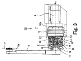
- Fig. 3 is a plan view, with portions broken away for clarity, of the taking out robot shown in Fig. 1.
- a taking out robot 30 of the present invention shown in Figs. 1 and 3 is used for taking out a molded product F of a movable die 2 used in an injection molding machine 10 as mentioned hereinafter.
- the injection molding machine 10 has a movable base 1 and a fixed base 3.
- the movable base 1 has a movable die 2, and the fixed base 3 has a fixed die 4.
- This movable base 1 can travel in directions shown with arrows Z1 and Z2.
- the fixed base 3 has a path (not shown) through which a material for a molded product F is injected into a cavity 5 to be defined between the movable die 2 and the fixed the 4.
- the injection molding machine 10 is used to produce a disc-like molded product F (referred to as molded product hereinafter), for instance, a rotary information-recording medium such as an optical disc or a magneto optical disc.
- the taking out robot 30 generally comprises a conversion mechanism 7 for converting a rotary motion of a main shaft 13 to a thrust motion of a cylindrical cam 17, a servomotor 9 to drive the conversion mechanism 7 through a reduction mechanism (referred to as reducer) 8 and a swing arm 6 connected to the conversion mechanism 7. Further, as shown in Fig. 1, a distal end portion of the swing arm 6 is bent to face the molded product F, and is provided with absorbing means 6a for securing the molded product F thereon.
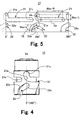
- the conversion mechanism 7 comprises the cylindrical cam 17 having a cylindrical surface on which a pair of driving cam grooves 22 and a pair of regulating cam grooves 21 (Figs. 3, 4) are defined, a swing arm 6 fixedly provided at one end of the cylindrical cam 17, a pair of driving cam followers 18, 18 engaged with the pair of driving cam grooves 22, 22 for driving the cylindrical cam 17 and a pair of fixed cam followers 19, 19 engaged with the pair of regulating cam grooves 21, 21 for regulating the motion of the cylindrical cam 17.
- the swing arm 6 holds the molded product F to remove it from the movable die 2.
- the swing arm 6 rotates along a plane of rotation to allow the molded product F to be detached from the swing arm 6 (Fig. 2).
- the swing arm 6 performs a thrust motion in a direction shown with an arrow R10 or R20, a rotary motion and an arcuate motion including the rotary and thrust motions as mentioned hereinafter.
- the cylindrical cam 17 is slidably provided on the main shaft 13 through a bearing 20. At an end of the cylindrical cam 17, the swing arm 6 is connected. Thus, the motion of the cylindrical cam 17 is directly transmitted to the swing arm 6.
- the main shaft 13 is rotatably connected to the servomotor 9 through the reducer 8.
- the cylindrical cam 17 is formed with the pair of driving cam grooves 22, 22 and the pair of regulation cam grooves 21, 21.
- the pair of driving cam followers 18, 18 are fixedly connected to a rotary bracket 16 at an interval of 180 degrees, and are engaged with the pair of driving cam grooves 22, 22.
- the rotary bracket 16 is integrally formed with the main shaft 13.
- the pair of fixed cam followers 19, 19 are connected to a fixed bracket 14 fixed to a main chassis 30a, and are engaged with the pair of regulating cam grooves 21, 21 of the cylindrical cam 17.
- the motion of the cylindrical cam 17 is regulated by the engagement of the fixed cam followers 19, 19 and the fixed cam followers 19, 19.
- the conversion mechanism 7 and the reducer 8 are rotatably connected through a rotary shaft 11
- the reducer 8 and the servomotor 9 are rotatably connected through another rotary shaft 12, respectively.
- the pair of fixed cam followers 19, 19 and the pair of driving cam followers 18 18 are respectively engaged with the regulating cam grooves 21, 21 and the driving cam grooves 22, 22 to increase reliability of the mechanism, however, the construction thereof is not limited to this embodiment.
- the construction thereof is not limited to this embodiment.
- the regulating cam grooves 21, 21 and the driving cam grooves 22 22 are formed on a surface side of the cylindrical cam 17, however, the construction thereof is not limited to this embodiment.
- Fig. 4 is a plan view of a cylindrical cam, which is a main part of the taking out robot shown in Fig. 3, and Fig. 5 is a development of the cylindrical cam shown in Fig. 4;
- a perpendicular direction shows a rotary angle of the cylindrical cam 17
- a vertical direction shows a traveling direction of the cylindrical cam 17 in a thrust direction parallel to a rotary axis Ax of the cylindrical cam 17.
- the cylindrical cam 17 there are formed with the pair of regulating cam grooves 21, 21, each having the same shape, separated at 180 degrees to each other, and the pair of driving cam grooves 22, 22, each having the same shape, separated at 180 degrees to each other.
- the description is given of one set of the regulating cam groove 21 and the driving cam groove 22.
- the regulating cam groove 21 has three portions, i.e., an arc groove portion (referred to as arc portion) Ga extended along a circumference of the cylindrical cam 17 for regulating a rotary motion and its rotary angle of the cylindrical cam 17, a thrust groove portion (referred to as thrust portion) Gt for regulating a thrust motion of the cylindrical cam 17 and a curved groove portion (referred to as curved portion) 21a for regulating both the rotary motion and the thrust motion of the cylindrical cam 17, i.e., an arcuate motion thereof.
- the curved portion 21a has a curvature R1 (Fig. 7 (A)) interposed between the arc portion Ga and the thrust portion Gt.
- the direction of the arc portion Ga is made to be perpendicular to a rotary axis Ax of the cylindrical cam 17.
- the maximum rotary angle Max ⁇ R of the cylindrical cam 17 is determined by an angle range of the arc portion Ga and an angle range in the rotary direction of the curved portion 21a, resulting in a maximum rotary angle Max ⁇ R of the swing arm 6 which is fixed to the end of the cylindrical cam 17.
- a direction of the thrust portion Gt is made to be parallel to the rotary axis Ax.
- a length of the thrust portion Gt and a component in the thrust direction of the curved portion 21a determine the maximum traveling distance Max ⁇ L of the cylindrical cam 17 in the thrust direction.
- a reference character 21e designates a distal end of the thrust portion Gt, and 21s a distal end of the arc portion Ga.
- the driving cam groove 22 also has three portions, a linear portion Dl, a second curved portion 22a and a slant portion Ds.
- the linear portion Dl is made to be parallel to the rotary axis Ax.
- the slant portion Ds is made to have an slant angle to the rotary axis Ax.
- the second curved portion 22a has a curvature R2 (Fig. 7(A)) interposed between the linear portion Dl and the slant portion Ds.
- a reference character 22e designates a distal end of the slant portion Ds.
- a component in the thrust direction of both the second curved portion 22a and the slant portion Ds corresponds to the maximum traveling distance Max ⁇ L mentioned in the foregoing.
- the driving cam groove 22 is formed so that the distal end 22e of the slant portion Ds is approximately positioned under the arc portion Ga of the regulation cam groove 21.
- the positional relation thereof is not limited to this embodiment. It is possible to form the driving cam groove 22 anywhere on the cylindrical cam 17, if necessary.
- Figs. 6 (A) to 6 (C) are enlarged plan views for explaining operations of the cylindrical cam by the engagement of cam followers with the cam grooves of the cylindrical cam shown in Fig. 5.
- the curvature R1 of the curved portion 21a in the regulating cam groove 21 is made to be the same as the curvature R2 of the second curved portion 22a of the driving cam groove 22.
- the regulating and driving cam grooves 21, 22 are formed so that a tangent line which touches the curved portion 21a at a vertex thereof and a tangent line which touches the second curved portion 22a at a vertex thereof intersect each other at right angles.
- the cylindrical cam 17 is rotated around the main rotary shaft 13 having the rotary axis Ax through the bearing 20, and is slidable over the main shaft 13 in the thrust direction parallel to the rotary axis Ax.
- the fixed cam follower 19 is fitly engaged with the regulating cam groove 21 at the end (21s) of the arc portion Ga and the driving cam follower 18 is fitly engaged with the driving cam groove 22 at the linear portion Dl thereof (Fig. 5).
- the fixed cam follower 19 is fixed on the fixed bracket 14 provided on the main chassis 30a and the driving cam follower 18 rotates around the rotary axis Ax of the main shaft 13 along a prescribed plane of rotation as shown in Fig. 3.
- the driving cam follower 18 is away from the fixed cam follower 19 by an angle ⁇ o, and one end of the cylindrical cam 17 is away from the driving cam follower 18 by a distance So.
- the driving cam follower 18 drives or rotates the cylindrical cam 17 around the rotary axis Ax in the same rotary direction XR by pushing a wall of the driving cam groove 22 in a normal direction.
- the cylindrical cam 17 is only rotated because its motion is regulated by the engagement of the fixed cam follower 19 and the arc portion Ga (Fig. 5) of the regulating cam groove 21.
- the cylindrical cam 17 is rotated along the arc portion Ga of the regulating cam groove 21.
- ⁇ 1 designates a rotary angle between the fixed cam follower 19 engaged with the curved portion 21a in the regulating cam groove 21 and the driving cam follower 18.
- the cylindrical cam 17 further moves downward in the thrust direction by being regulated with the engagement of the thrust portion Gt of the regulating cam groove 21 and the fixed cam follower 19 while the driving cam follower 18 is pushing and sliding the wall of the slant portion Ds of the driving cam groove 22.
- Figs. 7 (A) to 7 (F) are explanatory views showing relations between the cam grooves shown in Fig. 6 and the cam followers.
- Figs. 7 (A) to 7 (F) it should be noted that the fixed cam follower 19 is fixed on the main chassis 30a, and the driving cam follower 18 is fixed on the side of the main shaft 13 so as to be rotated along a predetermined plane of rotation which is keeping a constant distance from the fixed cam follower 19.
- the cylindrical cam 17 is moved around the main shaft 13 being regulated by causing the fixed and driving cam follower 19, 18 to engage with the regulating and driving cam grooves 21, 22 of the cylindrical cam 17.
- the overall shape of cylindrical cam 17 is not depicted but only the shapes of the regulating and driving cam grooves 21, 22, for simplicity.
- Fig. 7 (A) is a schematic view for explaining constructions of the regulating cam groove 21 and the driving cam groove 22.
- Fig. 7 (B) is a schematic view showing a state where the cylindrical cam 17 is only rotated in a rotary direction shown with an arrow XR, wherein the driving cam follower 18 is engaged with the linear portion Dl of the driving cam groove 22 and the fixed cam follower 19 is engaged with the arc portion Ga of the regulating cam groove 21.
- the driving cam follower 18 gives a normal force in a direction shown with an arrow to the wall of the linear portion Dl of the driving cam groove 22.
- the cylindrical cam 17 is only rotated around the main shaft 13 in the same direction as the normal force.
- the cylindrical cam 17 hardly accepts a large resist force from the fix cam follower 19. This enables an high-speed operation of the machine.
- Fig. 7 (C) is a schematic view showing a positional relation between the fixed and driving cam followers 19, 18 and the regulating and driving cam grooves 21, 22 of the cylindrical cam 17, wherein the cam cylinder 17 is rotated at a position where the end of the curved portion 21a in the regulating cam groove 21 is close to the fixed cam follower 19 by the engagement of the driving cam follower 18 and the linear portion D1 of the driving cam groove 22.
- a direction of the normal force to the wall of the second curved portion 22a in the driving cam groove 22 is shown with an arrow.
- a reference character ⁇ B1 designates an angle between an extended line in the direction of the normal force and an extended line in the rotary direction XR of the driving cam follower 18, S1 a standard line which is passing through a center of the fixed cam follower 19, and is parallel to the rotary direction (or a plane of rotation) XR of the driving can follower, and ⁇ A1 an angle between an extended line in the traveling direction of the cylindrical cam 17 shown with an arrow and the standard line Sl.
- the angle ⁇ A1 is made to be equal to the angle ⁇ B1 to allow the cylindrical cam 17 to move along the curved portion 21a without a resist force.
- a tangent line which touches the regulating cam groove 21 at a contact point of the fixed cam follower 19 and the tangent line which touches the driving cam groove 22 at a contact point of the driving cam follower 22 intersect at right angles. This enables a smooth motion of the cylindrical cam 17.
- Fig. 7 (D) is a schematic view showing a positional relation between the fixed and driving cam followers 19, 18 and the regulating and driving cam grooves 21, 22 of the cylindrical cam 17, wherein the cylindrical cam 17 is rotated at a position where a center of the curved portion 21a in the regulating cam groove 21 is close to the fixed cam follower 19 by the engagement of the driving cam follower 18 and the linear portion Dl of the driving cam groove 22.
- a direction of the normal force to the wall of the second curved portion 22a in the driving cam groove 22 is shown with an arrow, wherein a reference character ⁇ B2 designates an angle defined between an extended line in the direction of the normal force and an extended line in the rotary direction XR of the driving cam follower 18, and ⁇ A2 an angle defined between the standard line Sl and an extended line in a traveling direction of the cylindrical cam 17 shown with an arrow.
- the angle ⁇ A2 is made to be equal to the angle ⁇ B2.
- Fig. 7 (E) is a schematic view showing a positional relation between the fixed and driving cam followers and the regulating and driving cam grooves formed on the cylindrical cam, wherein the cylindrical cam 17 is rotated at a position where another end of the curved portion 21a in the regulating cam groove 21 is close to the fixed cam follower 19 by the engagement of the driving cam follower 18 and the linear portion D1 in the driving cam groove 22.
- a reference character ⁇ B3 designates an angle between an extended line in the direction of the normal force and an extended line in the rotary direction XR of the driving cam follower
- ⁇ A3 an angle defined between the standard line Sl and an extended line in a traveling direction of the cylindrical cam 17.
- the angle ⁇ A3 is made to be equal to the angle ⁇ B3.
- Fig. 7 (F) is a schematic view showing a state where the cylindrical cam 17 slidingly travels at a position where the end of the slant portion Ds in the driving cam groove 22 is engaged with the driving cam follower 18 at the end of the thrust portion Gt in the regulating cam groove 21.
- an angle between a direction of the normal force shown with an arrow to the wall of the slant portion Ds in the driving cam groove 22 and the rotary direction XR is made to be 60 degrees.
- the traveling direction of the cylindrical cam 17 becomes the thrust direction (90 degrees). This angle is a maximum of 90 degrees.
- the cylindrical cam 17 travels in the thrust direction downward.
- the driving cam follower 18 abates the end of the slant portion in the driving cam groove 22, the cylindrical cam 17 is moved in the thrust direction downward by the rotation of the driving cam follower 18.
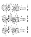
- Figs. 8 (A1) to 8 (C2) are explanatory views for explaining a relation between the swing arm and the conversion means in the taking out robot.
- Fig. 8 (A1) is a front view of the swing arm installed on the take out robot, and.
- Fig. 8 (A2) is a bottom view, with portions broken away for clarity, of Fig. 8 (A1).
- Fig. 7 (B) wherein the fixed and driving cam followers 19, 18 are engaged with the driving and regulating cam grooves 22, 21, respectively.
- the swing arm 6 is positioned, for instance, at the position A shown in Fig. 1.
- Fig. 8 (B1) is a front view of the swing arm installed on the taking out robot
- Fig. 8 (B2) is a bottom view, with portions broken away for clarity, of Fig. 8 (B1).
- These Figures are corresponding to Fig. 7 (C), and show a state where the swing arm 6 is traveling in a direction from the position A to the position B shown in Fig. 1.
- Fig. 8 (C1) is a front view of the swing arm installed on the taking out robot
- Fig. 8 (C2) is a bottom view, with portion broken away for clarity, of Fig. 8 (C1).
- Fig. 7 (F) wherein the fixed and driving cam followers 19, 18 are engaged with the regulating and driving cam grooves 21, 22, respectively.
- the swing arm 6 is positioned, for instance, at the position B shown in Fig. 1.
- Fig. 9 is a flow chart for explaining a taking out operation of a molded product from an injection molding machine employing the taking out robot of the present invention.
- Movable die 2 is at a closed state:
- the movable die 2 provided on the movable base 1 is at a closed state by being closely contacted with the fixed die 4 provided on the fixed base 3, wherein molding resin is injected between the movable and fixed dies 2, 4 to form a molded product F as shown in Fig. 1.
- the swing arm 6 is positioned at an initial position A as shown with tow-dotted lines in Figs. 1 and 2.
- the positional relation between the cylindrical cam 17 and the fixed cam follower 19 is shown in Fig. 6 (A), Fig.7 (B), Figs 8 (A1) and 8 (A2), wherein the driving cam followers 18 are present at the linear portion Dl in the driving cam groove 22 and the fixed cam follower 19 is engaged with the arc portion Ga in the regulating cam groove 21 of the cylindrical cam 17, respectively.
- the movable die 2 holding the molded product F starts on an opening operation from the fixed die 4 based on an operation program installed in the injection molding machine 10.
- the movable die 2 begins to separate from the fixed die 4.
- the movable die 2 stops at a predetermined position or a die opening position.
- This stop state is detected by detecting means such as sensors and switches (not shown) provided in the injection molding machine 10. These operations are intensively controlled by the operation program installed in the injection molding machine 10.
- a control device (not shown) provided in the injection molding machine 10 drives the servomotor 9 of the taking out robot 30 based on the direction of the control program.
- the rotation of the servomotor 9 is transmitted to the swing arm 6 through the reducer 8 and the conversion mechanism 7.
- the swing arm 6 starts to rotate in the direction shown with an arrow Rb shown in Fig.2. This state corresponds to Fig. 7 (B).
- the control device (not shown) servo-controls the servomotor 9 by transmitting a servo signal to the servomotor 9 to rotate it at an angle corresponding to a desired value.
- the reducer 8 rotates the main shaft 13.
- the swing arm 6 rotates in the direction shown with the arrow Rb shown in Fig. 2.
- This state corresponds to Fig. 7 (C).
- the swing arm 6 proceeds to an arcuate motion from the rotary motion.
- the swing arm 6 performs a thrust motion in the direction shown with the arrow R10 in Fig. 1 along with the rotary motion.
- This state corresponds to Fig.7 (D).
- Swing arm 6 absorbs and holds the molded product F with the absorbing means 6a:
- the swing arm 6 linearly proceeds close to the movable die 2 in the direction shown with the arrow R10 shown in Fig. 1.
- an ejecting pin (not shown) operates to eject the molded product F from the movable die 2.
- the molded product F ejected from the movable die 2 is held by the absorbing means 6a provided at an end of the swing arm 6. This corresponds to Fig.7 (F), wherein the cylindrical cam 17 moves in the thrust direction.
- Swing arm 6 starts on a taking out operation:
- the control device (not shown) transmits a servo signal to the servomotor 9 to rotate it inversely.
- the driving cam follower 18 returns to the initial state shown in Fig. 7 (B) from the state shown in Fig. 7 (F) through Fig. 7 (E) - Fig. 7 (C), in such a manner that the driving cam follower 18 is successively engaged with the distal end portion 22e, the slant portion Ds and the linear portion D1 in the driving cam groove 22.
- the cylindrical cam 17 also returns to the initial state shown in Fig. 7 (B) by being regulated by the engagement of the regulating cam groove 21 and the fixed cam follower 19.
- the molded product F is detached from the absorbing means 6a.
- the controlling device (not shown) out puts a signal to the injection molding machine 10 to close the movable die 2.
- a molding cycle time for molding for instance, a time required for producing a compact disc (CD) is reduced to 3.6 sec/cycle from 4 sec/cycle.
- a molding cycle time for molding for instance, a time required for producing a compact disc (CD) is reduced to 3.6 sec/cycle from 4 sec/cycle.
- the guiding structure comprises rotating means having a rotary shaft, conversion means for converting a rotary motion of the rotating means to a thrust motion of the swing arm, the conversion means disposed along the rotary shaft of the rotating means, and a swing arm connected to the conversion means, wherein the conversion means changes a rotary motion of the swing arm into the thrust motion thereof in a direction parallel to the rotary shaft through an arcuate motion thereof.
- the taking out robot when applied to an injection molding machine, it is possible to swiftly and securely take out the molded product from the molding die thereof.
Landscapes
- Engineering & Computer Science (AREA)
- Mechanical Engineering (AREA)
- General Engineering & Computer Science (AREA)
- Robotics (AREA)
- Manufacturing & Machinery (AREA)
- Transmission Devices (AREA)
- Moulds For Moulding Plastics Or The Like (AREA)
- Manipulator (AREA)
- Rotary Presses (AREA)
Applications Claiming Priority (4)
| Application Number | Priority Date | Filing Date | Title |
|---|---|---|---|
| JP21486499 | 1999-07-29 | ||
| JP21486499 | 1999-07-29 | ||
| JP2000100447 | 2000-04-03 | ||
| JP2000100447 | 2000-04-03 |
Publications (3)
| Publication Number | Publication Date |
|---|---|
| EP1072385A2 true EP1072385A2 (de) | 2001-01-31 |
| EP1072385A3 EP1072385A3 (de) | 2003-01-02 |
| EP1072385B1 EP1072385B1 (de) | 2004-10-06 |
Family
ID=26520552
Family Applications (1)
| Application Number | Title | Priority Date | Filing Date |
|---|---|---|---|
| EP00305403A Expired - Lifetime EP1072385B1 (de) | 1999-07-29 | 2000-06-27 | Führungsstruktur zum Regeln der Fahrrichtung eines Schwenkarms |
Country Status (4)
| Country | Link |
|---|---|
| US (1) | US6390804B1 (de) |
| EP (1) | EP1072385B1 (de) |
| CN (1) | CN1171714C (de) |
| DE (1) | DE60014524T2 (de) |
Cited By (1)
| Publication number | Priority date | Publication date | Assignee | Title |
|---|---|---|---|---|
| CN109130142A (zh) * | 2018-10-26 | 2019-01-04 | 张家港市格雷斯机械有限公司 | 用于挤出机的调节装置 |
Families Citing this family (8)
| Publication number | Priority date | Publication date | Assignee | Title |
|---|---|---|---|---|
| DE19955320C1 (de) * | 1999-11-17 | 2001-03-15 | Hansjuergen Moeser | Stell- und Regelvorrichtung für einen Heiß- oder Kaltkanal eines Kunststoff-Formwerkzeuges |
| JP2001293757A (ja) * | 2000-04-11 | 2001-10-23 | Nissei Plastics Ind Co | ディスク取出し装置 |
| JP3629189B2 (ja) * | 2000-08-09 | 2005-03-16 | ペンタックス株式会社 | 凸カムを有する成形カム環の成形方法、その成形型及び成形カム環 |
| JP2002130427A (ja) * | 2000-10-27 | 2002-05-09 | Zuiko Corp | カム装置 |
| US20060269652A1 (en) * | 2005-05-24 | 2006-11-30 | Husky Injection Molding Systems Ltd. | Article moving apparatus configured for molding machine |
| US7364423B2 (en) * | 2005-05-24 | 2008-04-29 | Husky Injection Molding Systems Ltd. | Article moving apparatus configured for a molding machine |
| JP6465615B2 (ja) * | 2014-10-22 | 2019-02-06 | 株式会社ユーシン精機 | 成形品取出機 |
| JP6382918B2 (ja) * | 2016-12-02 | 2018-08-29 | ファナック株式会社 | 成形機および成形品取出し装置を備える成形システム |
Citations (2)
| Publication number | Priority date | Publication date | Assignee | Title |
|---|---|---|---|---|
| EP0624448A1 (de) * | 1993-05-10 | 1994-11-17 | Sony Corporation | Roboter |
| EP0779141A1 (de) * | 1995-12-11 | 1997-06-18 | van den Brink B.V. | Vorrichtung zum Entfernen von Produkten aus einer Spritzgiessform |
-
2000
- 2000-06-27 DE DE60014524T patent/DE60014524T2/de not_active Expired - Fee Related
- 2000-06-27 EP EP00305403A patent/EP1072385B1/de not_active Expired - Lifetime
- 2000-07-05 US US09/610,493 patent/US6390804B1/en not_active Expired - Lifetime
- 2000-07-27 CN CNB001208071A patent/CN1171714C/zh not_active Expired - Fee Related
Patent Citations (2)
| Publication number | Priority date | Publication date | Assignee | Title |
|---|---|---|---|---|
| EP0624448A1 (de) * | 1993-05-10 | 1994-11-17 | Sony Corporation | Roboter |
| EP0779141A1 (de) * | 1995-12-11 | 1997-06-18 | van den Brink B.V. | Vorrichtung zum Entfernen von Produkten aus einer Spritzgiessform |
Cited By (1)
| Publication number | Priority date | Publication date | Assignee | Title |
|---|---|---|---|---|
| CN109130142A (zh) * | 2018-10-26 | 2019-01-04 | 张家港市格雷斯机械有限公司 | 用于挤出机的调节装置 |
Also Published As
| Publication number | Publication date |
|---|---|
| CN1282656A (zh) | 2001-02-07 |
| DE60014524T2 (de) | 2005-02-03 |
| US6390804B1 (en) | 2002-05-21 |
| EP1072385A3 (de) | 2003-01-02 |
| DE60014524D1 (de) | 2004-11-11 |
| EP1072385B1 (de) | 2004-10-06 |
| CN1171714C (zh) | 2004-10-20 |
Similar Documents
| Publication | Publication Date | Title |
|---|---|---|
| EP1072385B1 (de) | Führungsstruktur zum Regeln der Fahrrichtung eines Schwenkarms | |
| US6183235B1 (en) | Electrically-operated injection molding machine | |
| JPH06104330B2 (ja) | 射出成形機の製品突出し装置 | |
| EP0624448B1 (de) | Roboter | |
| US4819850A (en) | Material feeding apparatus | |
| JP3054928B2 (ja) | インモールドラベル貼付装置 | |
| CN215396683U (zh) | 可多次合模的肘杆式合模装置 | |
| JP3883032B2 (ja) | スイングアームの移動方向案内装置 | |
| JPS5814298B2 (ja) | 成形用金型 | |
| CN220198427U (zh) | 弧形扣位脱模机构及模具 | |
| KR100470774B1 (ko) | 소형물 수납장치 | |
| JPH06198583A (ja) | ロボット | |
| JPS5816841Y2 (ja) | 容器成形用金型のアンダ−カット処理装置 | |
| JPH0233970Y2 (de) | ||
| JPH0732287A (ja) | アームの移動方向案内装置とアームの移動方向案内方法 | |
| JP4117756B2 (ja) | 射出成形機のゲートカット装置およびゲートカット方法 | |
| JP2587250B2 (ja) | ねじ射出成形装置 | |
| JPH01130357A (ja) | カセットローディング装置 | |
| JPS5816842Y2 (ja) | 容器成形金型のアンダ−カット処理装置 | |
| JPH0724752A (ja) | 対象物の取り出し方法と取り出しロボット | |
| CN112727301A (zh) | 一种自动开门机 | |
| KR850000120B1 (ko) | 자기테이프 기록재생장치 | |
| JPH07112461A (ja) | 対象物の取り出し機 | |
| JPH10258448A (ja) | 旋回式樹脂成形品の取出し装置 | |
| JP3573805B2 (ja) | カセットケースへの磁気テープ巻き取り装置 |
Legal Events
| Date | Code | Title | Description |
|---|---|---|---|
| PUAI | Public reference made under article 153(3) epc to a published international application that has entered the european phase |
Free format text: ORIGINAL CODE: 0009012 |
|
| AK | Designated contracting states |
Kind code of ref document: A2 Designated state(s): AT BE CH CY DE DK ES FI FR GB GR IE IT LI LU MC NL PT SE |
|
| AX | Request for extension of the european patent |
Free format text: AL;LT;LV;MK;RO;SI |
|
| PUAL | Search report despatched |
Free format text: ORIGINAL CODE: 0009013 |
|
| AK | Designated contracting states |
Kind code of ref document: A3 Designated state(s): AT BE CH CY DE DK ES FI FR GB GR IE IT LI LU MC NL PT SE |
|
| AX | Request for extension of the european patent |
Free format text: AL;LT;LV;MK;RO;SI |
|
| RIC1 | Information provided on ipc code assigned before grant |
Free format text: 7B 29C 45/42 A, 7F 16H 25/18 B |
|
| 17P | Request for examination filed |
Effective date: 20030102 |
|
| 17Q | First examination report despatched |
Effective date: 20030224 |
|
| AKX | Designation fees paid |
Designated state(s): DE FR GB |
|
| GRAP | Despatch of communication of intention to grant a patent |
Free format text: ORIGINAL CODE: EPIDOSNIGR1 |
|
| GRAS | Grant fee paid |
Free format text: ORIGINAL CODE: EPIDOSNIGR3 |
|
| GRAA | (expected) grant |
Free format text: ORIGINAL CODE: 0009210 |
|
| AK | Designated contracting states |
Kind code of ref document: B1 Designated state(s): DE FR GB |
|
| REG | Reference to a national code |
Ref country code: GB Ref legal event code: FG4D |
|
| REG | Reference to a national code |
Ref country code: IE Ref legal event code: FG4D |
|
| REF | Corresponds to: |
Ref document number: 60014524 Country of ref document: DE Date of ref document: 20041111 Kind code of ref document: P |
|
| PLBE | No opposition filed within time limit |
Free format text: ORIGINAL CODE: 0009261 |
|
| STAA | Information on the status of an ep patent application or granted ep patent |
Free format text: STATUS: NO OPPOSITION FILED WITHIN TIME LIMIT |
|
| ET | Fr: translation filed | ||
| 26N | No opposition filed |
Effective date: 20050707 |
|
| PGFP | Annual fee paid to national office [announced via postgrant information from national office to epo] |
Ref country code: DE Payment date: 20070621 Year of fee payment: 8 |
|
| PGFP | Annual fee paid to national office [announced via postgrant information from national office to epo] |
Ref country code: GB Payment date: 20070627 Year of fee payment: 8 |
|
| PGFP | Annual fee paid to national office [announced via postgrant information from national office to epo] |
Ref country code: FR Payment date: 20070608 Year of fee payment: 8 |
|
| GBPC | Gb: european patent ceased through non-payment of renewal fee |
Effective date: 20080627 |
|
| REG | Reference to a national code |
Ref country code: FR Ref legal event code: ST Effective date: 20090228 |
|
| PG25 | Lapsed in a contracting state [announced via postgrant information from national office to epo] |
Ref country code: DE Free format text: LAPSE BECAUSE OF NON-PAYMENT OF DUE FEES Effective date: 20090101 |
|
| PG25 | Lapsed in a contracting state [announced via postgrant information from national office to epo] |
Ref country code: GB Free format text: LAPSE BECAUSE OF NON-PAYMENT OF DUE FEES Effective date: 20080627 |
|
| PG25 | Lapsed in a contracting state [announced via postgrant information from national office to epo] |
Ref country code: FR Free format text: LAPSE BECAUSE OF NON-PAYMENT OF DUE FEES Effective date: 20080630 |