EP1070864A1 - Palier à billes - Google Patents
Palier à billes Download PDFInfo
- Publication number
- EP1070864A1 EP1070864A1 EP00115582A EP00115582A EP1070864A1 EP 1070864 A1 EP1070864 A1 EP 1070864A1 EP 00115582 A EP00115582 A EP 00115582A EP 00115582 A EP00115582 A EP 00115582A EP 1070864 A1 EP1070864 A1 EP 1070864A1
- Authority
- EP
- European Patent Office
- Prior art keywords
- inner ring
- ball bearing
- diameter
- balls
- expressed
- Prior art date
- Legal status (The legal status is an assumption and is not a legal conclusion. Google has not performed a legal analysis and makes no representation as to the accuracy of the status listed.)
- Granted
Links
- 230000002093 peripheral effect Effects 0.000 claims description 38
- 229910000831 Steel Inorganic materials 0.000 claims description 12
- 239000010959 steel Substances 0.000 claims description 12
- 238000012360 testing method Methods 0.000 description 52
- 239000004519 grease Substances 0.000 description 12
- 238000005096 rolling process Methods 0.000 description 12
- 238000004299 exfoliation Methods 0.000 description 6
- 230000000694 effects Effects 0.000 description 4
- 230000036316 preload Effects 0.000 description 3
- 239000000919 ceramic Substances 0.000 description 2
- 238000005461 lubrication Methods 0.000 description 2
- 238000012986 modification Methods 0.000 description 2
- 230000004048 modification Effects 0.000 description 2
- -1 SUJ2 or M50 Substances 0.000 description 1
- 238000004378 air conditioning Methods 0.000 description 1
- 238000012790 confirmation Methods 0.000 description 1
- 230000003247 decreasing effect Effects 0.000 description 1
- 238000013461 design Methods 0.000 description 1
- 239000000428 dust Substances 0.000 description 1
- 239000010687 lubricating oil Substances 0.000 description 1
- 238000004519 manufacturing process Methods 0.000 description 1
- 239000000463 material Substances 0.000 description 1
- 238000005259 measurement Methods 0.000 description 1
- 239000000843 powder Substances 0.000 description 1
- 238000003825 pressing Methods 0.000 description 1
- 238000003908 quality control method Methods 0.000 description 1
- 230000000630 rising effect Effects 0.000 description 1
- 238000003860 storage Methods 0.000 description 1
- 238000007669 thermal treatment Methods 0.000 description 1
Images


Classifications
-
- F—MECHANICAL ENGINEERING; LIGHTING; HEATING; WEAPONS; BLASTING
- F16—ENGINEERING ELEMENTS AND UNITS; GENERAL MEASURES FOR PRODUCING AND MAINTAINING EFFECTIVE FUNCTIONING OF MACHINES OR INSTALLATIONS; THERMAL INSULATION IN GENERAL
- F16C—SHAFTS; FLEXIBLE SHAFTS; ELEMENTS OR CRANKSHAFT MECHANISMS; ROTARY BODIES OTHER THAN GEARING ELEMENTS; BEARINGS
- F16C33/00—Parts of bearings; Special methods for making bearings or parts thereof
- F16C33/30—Parts of ball or roller bearings
- F16C33/58—Raceways; Race rings
-
- F—MECHANICAL ENGINEERING; LIGHTING; HEATING; WEAPONS; BLASTING
- F16—ENGINEERING ELEMENTS AND UNITS; GENERAL MEASURES FOR PRODUCING AND MAINTAINING EFFECTIVE FUNCTIONING OF MACHINES OR INSTALLATIONS; THERMAL INSULATION IN GENERAL
- F16C—SHAFTS; FLEXIBLE SHAFTS; ELEMENTS OR CRANKSHAFT MECHANISMS; ROTARY BODIES OTHER THAN GEARING ELEMENTS; BEARINGS
- F16C19/00—Bearings with rolling contact, for exclusively rotary movement
- F16C19/02—Bearings with rolling contact, for exclusively rotary movement with bearing balls essentially of the same size in one or more circular rows
- F16C19/04—Bearings with rolling contact, for exclusively rotary movement with bearing balls essentially of the same size in one or more circular rows for radial load mainly
- F16C19/06—Bearings with rolling contact, for exclusively rotary movement with bearing balls essentially of the same size in one or more circular rows for radial load mainly with a single row or balls
-
- F—MECHANICAL ENGINEERING; LIGHTING; HEATING; WEAPONS; BLASTING
- F16—ENGINEERING ELEMENTS AND UNITS; GENERAL MEASURES FOR PRODUCING AND MAINTAINING EFFECTIVE FUNCTIONING OF MACHINES OR INSTALLATIONS; THERMAL INSULATION IN GENERAL
- F16C—SHAFTS; FLEXIBLE SHAFTS; ELEMENTS OR CRANKSHAFT MECHANISMS; ROTARY BODIES OTHER THAN GEARING ELEMENTS; BEARINGS
- F16C2240/00—Specified values or numerical ranges of parameters; Relations between them
- F16C2240/40—Linear dimensions, e.g. length, radius, thickness, gap
- F16C2240/60—Thickness, e.g. thickness of coatings
-
- F—MECHANICAL ENGINEERING; LIGHTING; HEATING; WEAPONS; BLASTING
- F16—ENGINEERING ELEMENTS AND UNITS; GENERAL MEASURES FOR PRODUCING AND MAINTAINING EFFECTIVE FUNCTIONING OF MACHINES OR INSTALLATIONS; THERMAL INSULATION IN GENERAL
- F16C—SHAFTS; FLEXIBLE SHAFTS; ELEMENTS OR CRANKSHAFT MECHANISMS; ROTARY BODIES OTHER THAN GEARING ELEMENTS; BEARINGS
- F16C2240/00—Specified values or numerical ranges of parameters; Relations between them
- F16C2240/40—Linear dimensions, e.g. length, radius, thickness, gap
- F16C2240/70—Diameters; Radii
- F16C2240/76—Osculation, i.e. relation between radii of balls and raceway groove
-
- F—MECHANICAL ENGINEERING; LIGHTING; HEATING; WEAPONS; BLASTING
- F16—ENGINEERING ELEMENTS AND UNITS; GENERAL MEASURES FOR PRODUCING AND MAINTAINING EFFECTIVE FUNCTIONING OF MACHINES OR INSTALLATIONS; THERMAL INSULATION IN GENERAL
- F16C—SHAFTS; FLEXIBLE SHAFTS; ELEMENTS OR CRANKSHAFT MECHANISMS; ROTARY BODIES OTHER THAN GEARING ELEMENTS; BEARINGS
- F16C33/00—Parts of bearings; Special methods for making bearings or parts thereof
- F16C33/30—Parts of ball or roller bearings
- F16C33/58—Raceways; Race rings
- F16C33/583—Details of specific parts of races
- F16C33/585—Details of specific parts of races of raceways, e.g. ribs to guide the rollers
Definitions
- the present invention relates to a ball bearing, and particularly a ball bearing used to support a rotary shaft, which is disposed in a fan motor of an electric cleaner for domestic use or in a blower of an air conditioner for domestic use and is to be rotated at a high speed with a low load, in such a manner that the rotary shaft can be rotated freely with respect to a housing.
- the ball bearing 1 is widely used to support a rotary shaft, which is disposed in various apparatus, in such a manner that it can be freely rotated with respect to a housing.
- the ball bearing 1 comprises an outer ring 3 including on the inner peripheral surface thereof a deep-groove type of outer ring raceway 2 having an arc-shaped section, an inner ring 5 including on the outer peripheral surface thereof an inner ring raceway 4 having an arc-shaped section, and a plurality of balls 6 respectively interposed between the outer and inner ring raceways 2 and 4 so as to be free to roll; and, the outer ring 3, inner ring 5 and balls 6 are all made of bearing steel such as SUJ2 or M50, ceramic, or the like.
- the balls 6 are respectively held by a retainer 7 in such a manner that they are able to roll while they are spaced from one another. Also, to the inner peripheral surfaces of the two end portions of the outer ring 3, there are secured the outer peripheral edge portions of sealed rings 8 and 8, whereas the inner peripheral edge portions of the sealed rings 8 and 8 are respectively disposed so as to be close and opposed to the outer peripheral surfaces of the two end portions of the inner ring 5.
- the outside diameter of the outer ring 3 is expressed as D
- the inside diameter of the inner ring 5 is expressed as d
- the pitch circle diameter (P.C.D.) of the respective balls 6 is expressed as Dp'
- the following equation is established; that is, Dp' ⁇ (D + d) / 2 .
- the equation that is, Dp' / (D + d) / 2 ⁇ 1
- the respective balls 6 are positioned substantially in the middle of the outer peripheral surface of the outer ring 3 and the inner peripheral surface of the inner ring 5 with respect to the diameter direction of the ball bearing 1.
- the outer ring 3 is inserted and fixed to a fixed housing, while the inner ring 5 is outserted and fixed to the rotary shaft.
- the above-mentioned conventional ball bearing 1 has a general-purpose structure which aims for assembly into one of various rotation support portions, but does not prefer to apply under the low-load and high-speed rotation condition, and, therefore, the rotation torque (rotation resistance) thereof is not always low.
- the rotation torque rotation resistance
- the present invention aims at eliminating the above-mentioned drawbacks found in the conventional ball bearing,
- a ball bearing which, similarly to the above-mentioned conventional ball bearing, comprises an outer ring including on the inner peripheral surface thereof an outer ring raceway having an arc-shaped section; an inner ring including on the outer peripheral surface thereof an inner ring raceway having an arc-shaped section; and, a plurality of balls respectively and interposed rollably between the outer and inner ring raceways.
- the outside diameter of the outer ring is expressed as D
- the inside diameter of the inner ring is expressed as d
- the pitch circle diameter of the respective balls is expressed as Dp
- the radius of curvature of the section shape of the outer ring raceway is expressed as Ro
- the radius of curvature of the section shape of the inner ring raceway is expressed as Ri
- the plurality of balls are positioned on the inside diameter side of the ball bearing. This can reduce the moment necessary to roll these balls, thereby being able to reduce the rotation torque of the ball bearing.
- the inner ring raceway (groove bottom) surface Di depends on the fit standard js5 specified in JIS and on the strength that is required of the inner ring. That is, according to the js5, the upper limit value of the interference of an inner ring is 11 ⁇ m in the case of an inner ring having an inside diameter of 6 - 10 mm and, in the case of an inner ring having an inside diameter of 10 - 18 mm, it is 12 ⁇ m.
- the outer ring, the inner ring and the plurality of balls are preferably made of bearing steel.
- the inner ring raceway surface Di having an influence on the thickness of the groove bottom of the inner ring is specified in such a manner that the maximum stress of bearing steel can be of 137.2 MPa (14 kgf/mm 2 ) or less.
- the maximum stress of bearing steel can be of 137.2 MPa (14 kgf/mm 2 ) or less.
- the inner ring raceway surface Di is set at the value where the maximum circumstantial stress provides 294MPa (30 kgf/mm 2 ).
- the ratio is set such that 0.52 ⁇ R l /D b ⁇ 0.65 ; but, as in a fan motor used in a suction device of an electric cleaner, when the fan motor is used at a speed of 20000 min -1 (r.p.m.) or more, preferably, the ratio may be set such that 0.53 ⁇ R l / D b ⁇ 0.65 .
- contact ellipses which are formed in the contact portions between the rolling surfaces of the balls and the outer ring and inner ring raceways can be reduced in size so that rolling resistance and spin, which are caused in the contact ellipse portions during rotation, can be reduced to thereby be able to reduce the rotation torque of the ball bearing.
- the values of Ro / Db and Ri / Db exceed 0. 65 and increase excessively, the area of each of the contact ellipses is reduced excessively, which makes it difficult to secure the rolling fatigue lives of the outer and inner ring raceways; and, especially, in the case of the outer ring raceway, Brinell impressions are easy to occur.
- the upper limit values of Ro / Db and Ri / Db are set at 0.65.
- the present electric cleaner ball bearing is incorporated into the rotation support portion of the electric cleaner and is used in such a manner that the outer ring is fixed and the inner ring is rotated at the speed of 40,000 - 60,000 min -1 (r.p.m).
- the diameter of the respective balls is expressed as Db
- the radius of curvature of the section shape of the outer ring raceway is expressed as Ro
- the radius of curvature of the section shape of the inner ring raceway is expressed as Ri
- the reason why, as described above, the ratios of the radius of curvature of the section shape of the outer ring raceway Ro and the radius of curvature of the section shape of the inner ring raceway Ri to the diameter of the respective balls Db are respectively set in the range of 58 - 61% is as follows. That is, as these ratios increase, the contact ellipses formed in the respective contact portions decrease in size, thereby being able to reduce the rotation torque of the ball bearing. Therefore, in order to reduce the rotation torque of the ball bearing, it is preferred to increase these ratios (that is, Ro / Db and Ri / Db).
- a ball bearing 1a similarly to the conventionally known ball bearing 1 that is shown in the above-mentioned Fig. 11, comprises an outer ring 3a including on the inner peripheral surface thereof a deep-groove type of outer ring raceway 2a having an arc-shaped section, an inner ring 5a including on the outer peripheral surface thereof an inner ring raceway 4a having an arc-shaped section, and a plurality of balls 6 respectively interposed between the outer and inner ring raceways 2a and 4a so as to be free to roll.
- the balls 6 are respectively held by a retainer 7 in such a manner that they are able to roll while they are spaced from one another.
- the outer ring 3a, the inner ring 5a and the plurality of balls 6 are preferably made of bearing steel, such as SUJ2, M50 or the like in this embodiment. It is, however, possible to make them with a steel, a ceramic or the like instead of the bearing steel, if required.
- the outside diameter of the outer ring 3a is expressed as D
- the inside diameter of the inner ring is expressed as d
- the pitch circle diameter of the respective balls 6 is expressed as Dp
- the radius of curvature of the section shape of the outer ring raceway 2a is expressed as Ro
- the radius of curvature of the section shape of the inner ring raceway 4a is expressed as Ri
- the ball bearing 1a is a ball bearing which not only is used to support the rotary shaft of a domestic-use electric cleaner or the rotary shaft of a blower of a domestic-use air conditioner on a housing but also is used under a low-load and high-speed rotation condition.
- the outside diameter D of the outer ring 3a is of the order of 15 - 40 mm
- the inside diameter d of the inner ring 5a is of the order of 6 - 18 mm
- the width B of the ball bearing 1a is of the order of 5 - 12 mm.
- D l in the equation (3) expresses the diameter of an inner ring raceway which provides the maximum circumferential stress of 294 MPa (30 kgf/mm 2 ), under the condition that the interference of the inner ring is expressed by a curved line allowing the following three points to be smoothly continuous with one another, that is, a first point where the inner ring interference is 6 ⁇ m for the inner ring inside diameter of 5mm, a second point where the inner ring interference is 2 ⁇ m for the inner ring inside diameter of 4mm, and, a third point where the inner ring interference is 1 ⁇ m for the inner ring inside diameter 3 mm.
- a straight line D which is situated downwardly of the triangular portion, shows a portion in which the thickness of the inner ring 5a provides 0 in the above-mentioned inner ring raceway 4a portion. Therefore, downwardly of the straight line D, the present ball bearing cannot be established.
- the thickness of the outer ring 3a with respect to the diameter direction of the ball bearing 1a is set larger than the thickness of the inner ring 5a, and the positions of the balls 6 (that is, pitch circle diameters thereof) are arranged on the inside diameter side of the ball bearing 1a. That is, by manufacturing the ball bearing 1a downwardly of the straight line A in Fig. 2, the moment that is necessary to roll the balls 6 can be reduced to thereby be able to reduce the rotation torque of the ball bearing 1a.
- the housing which has been conventionally used, can be used as it is.
- the pitch circle diameter D p is reduced to thereby be able to reduce the torque
- y ⁇ 1 as in the equation (2).
- the value of y may be set equal to or less than 0.95 and, more preferably, the value of y may be set equal to or less than 0.9.
- the lower limit value of y is restricted by a straight line C shown in Fig. 2.
- the contact ellipses in the contact portions between the rolling surfaces of the balls 6 and the outer ring raceway 2a can be prevented from being excessively reduced in size, which in turn can prevent Brinell impressions from being caused in the outer ring raceway 2a. That is, the diameter Db of the balls 6 is secured in such a manner that the ball bearing 1a can be manufactured on the right side of the straight line B in Fig. 2.
- the outer ring raceway 2a is structured in such a manner that not only its cross section extending in the axial direction of the ball bearing 1a is a concave surface but also its cross section extending in the circumferential direction of the ball bearing 1a is also a concave surface.
- the thus structured outer ring raceway 2a is smaller in yield strength with respect to a pressing force applied thereto than the inner ring raceway 4a whose cross section extending in the circumferential direction of the ball bearing 1a is a convex surface.
- the maximum surface pressure to be applied onto the outer ring raceway 2a is controlled down to 1960 MPa (200 kgf/mm 2 ) or less, which makes it possible to prevent the Brinell impressions from being caused in the outer ring raceway 2a.
- the maximum tensile stress can be controlled down to 294 Mpa (30 kgf/mm 2 ) or less, which makes it possible to prevent the inner ring 5a against such damage.
- contact ellipses which are formed in the contact portions between the rolling surfaces of the balls 6 and the outer ring and inner ring raceways 2a, 4a, can be reduced in size so that rolling resistance and spin, which are caused in the contact ellipse portions during rotation, can be reduced to thereby be able to reduce the rotation torque of the ball bearing 1a.
- These hold recessed portions 16, 16 respectively function as grease storage portions and can continue to supply lubricating oil to the contact portions between the rolling surfaces of the balls 6 and the outer ring raceway 2a, inner ring raceway 4a for a long period of time.
- the capacities of the hold recessed portions 16, 16 can be increased and thus the grease hold quantities thereof can be increased, thereby being able to enhance the durability of the ball bearing 1b.
- the remaining portions of the structure and operation of the present example are similar to those of the previously described first example.
- test a test (a first test) which was conducted in order to know the influence of the pitch circle diameter D p of the ball 6 on the rotation torque of the ball bearing; a test (a second test) conducted in order to know the influence of the radiuses of curvature of the section shapes of the respective raceways on the rotation torque of the ball bearing; and, a test (a third test) conducted in order to know the influences of the pitch circle diameter D p of the ball 6 and the diameter D b of the ball 6 on the noise that is produced by the motor.
- the test apparatus 9 comprises a rotary shaft 10 and a housing 11 which are disposed concentric with each other.
- ball bearings 1a, 1a having the same structure were assembled between the outer peripheral surface of the rotary shaft 10 and the inner peripheral surface of the housing 11 and, after then, the rotary shaft 10 was rotated, whereby rotation torque applied to the leading end portion of an arm 12 fixed to the outer peripheral surface of the housing was measured by a load sensor 13.
- a load sensor 13 By the way, in every sample, grease for lubrication was applied into the ball bearings 1a, 1a and two end portions of the ball bearings 1a, 1a were sealed by sealed rings 8, 8 each of a non-contact type (see Fig. 1). Also, the test apparatus was operated at room temperature in the air.
- a preload of 49N (5 kgf) was applied to the respective ball bearings 1a, 1a using a spring 14.
- FIG. 4 shows the results of the test conducted in this manner.
- the test the results of which are shown in the table 1 was conducted using a ball bearing of a deep groove type in which the outside diameter D of an outer ring 3a is 22 mm, the inside diameter d of an inner ring 4a is 8 mm, and the width B of the bearing is 7mm. Also, the ratio of the grease quantity with respect to the capacity of a gap existing between the outer ring 3a and inner ring 4a (that is, the grease filling ratio) was set at 35%, and the rotation speed of the motor was set at 1800 min -1 .
- the test the results of which are shown in the table 2 was conducted using a ball bearing of a deep groove type in which the outside diameter D of an outer ring 3a is 32 mm, the inside diameter d of an inner ring 4a is 15 mm, and the width B of the bearing is 9 mm. Also, the ratio of the grease quantity with respect to the capacity of a gap existing between the outer ring 3a and inner ring 4a was set at 30%, and the rotation speed of the motor was set at 3.800 min -1 .
- the unit that is used to express the value of the rotation torque shown in Tables 1 and 2 is mN ⁇ cm.
- Table 3 also shows that, by increasing the value of the ratios of the radiuses of curvature R o , R l of the respective raceways to the diameter D b of the rolling bodies, the rotation torque of the ball bearing can be reduced.
- R l / D b 0.51
- R l / D b 0.52
- the test aiming at confirming the influences of the pitch circle diameter D p of the ball 6 and the diameter D b of the ball 6 on the ANDELON value was conducted using a ball bearing of a deep groove type in which the outside diameter D of an outer ring 3a is 22 mm, the inside diameter d of an inner ring 4a is 8 mm, the width B of the bearing is 7 mm, and the grease filling ratio is set at 35%.
- Fig. 7 there are shown six marks for each of the two kinds of samples respectively having different pitch circle diameters D p , that is, a total of twelve marks.
- a white round mark expresses the average value of the motor noises that were produced when using the ball, bearing whose pitch circle diameter D p is 21.5 mm
- a white triangular mark expresses the maximum value thereof
- a while square mark expresses the minimum value thereof, respectively
- a black round mark expresses the average value of the motor noises that were produced when using the ball bearing whose pitch circle diameter D p is 23 mm
- a black triangular mark expresses the maximum value thereof
- a black square mark expresses the minimum value thereof, respectively.
- Fig. 7 which shows the results of the above test, in case where the pitch circle diameter D p is reduced, even when the ANDELON value is worsened, there can be prevented an increase in the value of the motor noise that is produced when the ball bearing is actually incorporated into the motor.
- the pitch circle diameter D p is reduced, instead of reducing the diameter D b of the balls to thereby increase the number of the balls, the diameter D b of the balls can be reduced and, therefore, of the vibration components of the balls, the number of resonance peaks included in the resonance frequency range with respect to the motor is reduced, which operates to advantage in sound.
- the radius of curvature of the section shape of the outer ring raceway 2c is expressed as Ro
- the radius of curvature of the section shape of the inner ring raceway 4c is expressed as Ri
- the ball bearing 1c is a ball bearing which not only is used to support the rotary shaft of a blower of a domestic-use electric cleaner but also is used under the low-load and high-speed rotation condition.
- the outside diameter D of the outer ring 3c is of the order of 15- 40mm
- the inside diameter d of the inner ring 5c is of the order of 6 - 18 mm
- the width B of the ball bearing 1c is of the order of 5 - 12 mm.
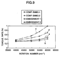
- the test was conducted using a deep-groove type of ball bearing in which the outside diameter D of an outer ring 3c is 22 mm, the inside diameter d of an inner ring 5c is 8 mm, and the width of the ball bearing is 7 mm.
- the outer ring 3c, inner ring 5c and balls 6 are all made of steel SUJ2.
- the test apparatus 9 comprises a rotary shaft 10 and a housing 11 which are disposed concentric with each other.
- a preload of 49 N (5 kgf) was applied to the ball bearings 1c, 1c by a spring 14.
- the rotation speed of the rotary shaft 10 was varied in the range of 40,000 - 60,000 min -1 and the rotation torque of the ball bearing after the passage of ten minutes from the start of the operation of the test apparatus was measured for every rotation speed.
- a solid line a shows the test results of the embodiment 1
- a broken line b shows the test results of the embodiment 2
- a one-dot chained line c shows the test results of the comparison example 1
- a two-dot chained line d shows the test results of the comparison example 2, respectively.
- a ball bearing according to the first aspect of the invention is structured and operates in the above-mentioned manner, the present ball bearing can reduce the rotation resistance or rotation torque of the rotation support portions of various machines and apparatus, thereby being able to save energy when operating such machines and apparatus.
- a ball bearing for an electric cleaner according to the second aspect of the invention is structured and operates in the above-mentioned manner, the present ball bearing not only can secure practically sufficient durability but also can reduce the rotation resistance or rotation torque of the rotation support portion of the electric cleaner, thereby being able to save energy when operating such electric cleaner.
Applications Claiming Priority (4)
| Application Number | Priority Date | Filing Date | Title |
|---|---|---|---|
| JP20524599 | 1999-07-19 | ||
| JP20524599 | 1999-07-19 | ||
| JP2000007930 | 2000-01-17 | ||
| JP2000007930A JP2001200850A (ja) | 2000-01-17 | 2000-01-17 | 電気掃除機用玉軸受 |
Publications (2)
| Publication Number | Publication Date |
|---|---|
| EP1070864A1 true EP1070864A1 (fr) | 2001-01-24 |
| EP1070864B1 EP1070864B1 (fr) | 2005-09-28 |
Family
ID=26514949
Family Applications (1)
| Application Number | Title | Priority Date | Filing Date |
|---|---|---|---|
| EP00115582A Expired - Lifetime EP1070864B1 (fr) | 1999-07-19 | 2000-07-19 | Palier à billes |
Country Status (4)
| Country | Link |
|---|---|
| US (3) | US6524008B1 (fr) |
| EP (1) | EP1070864B1 (fr) |
| CN (1) | CN1260483C (fr) |
| DE (1) | DE60022833T2 (fr) |
Cited By (4)
| Publication number | Priority date | Publication date | Assignee | Title |
|---|---|---|---|---|
| US6634792B1 (en) * | 1999-04-16 | 2003-10-21 | Skf France | Rigid anti-friction ball-bearing |
| EP1450058A2 (fr) * | 2003-02-18 | 2004-08-25 | Koyo Seiko Co., Ltd. | Palier à rouleaux avec bague en matériau céramique |
| EP1541883A1 (fr) * | 2002-07-23 | 2005-06-15 | Nsk Ltd., | Roulement a billes |
| ITTV20090015A1 (it) * | 2009-02-10 | 2010-08-11 | T M Technology Srl | Struttura di cuscinetto a sfere |
Families Citing this family (15)
| Publication number | Priority date | Publication date | Assignee | Title |
|---|---|---|---|---|
| CN1260483C (zh) * | 1999-07-19 | 2006-06-21 | 日本精工株式会社 | 滚珠轴承 |
| WO2003064872A1 (fr) * | 2002-01-31 | 2003-08-07 | Nsk Ltd. | Palier de poulie pour accessoire de moteur d'automobile |
| JPWO2003071142A1 (ja) * | 2002-02-20 | 2005-06-16 | 日本精工株式会社 | コンプレッサ用プーリの回転支持装置 |
| KR100642589B1 (ko) * | 2002-09-06 | 2006-11-10 | 닛뽄 세이꼬 가부시기가이샤 | 차륜 지지용 구름 베어링 유닛 |
| EP1693581B1 (fr) * | 2003-12-11 | 2010-08-25 | JTEKT Corporation | Dispositif de palier pour arbre de pignon |
| DE102006015296B4 (de) * | 2006-04-01 | 2012-10-18 | Schaeffler Kg | Schrägkugellager, insbesondere mehrreihiges Radlager für die Radaufhängung eines Kraftfahrzeuges |
| US20100183256A1 (en) * | 2006-08-25 | 2010-07-22 | Nsk Ltd. | Angular ball bearing |
| AU2012214503A1 (en) * | 2011-02-08 | 2013-08-22 | General Electric Company | Cylindrical roller bearing apparatus |
| US8801383B2 (en) * | 2011-06-29 | 2014-08-12 | Hamilton Sundstrand Corporation | Ball bearing retention for propeller blade and method of assembly |
| JP5509183B2 (ja) | 2011-11-29 | 2014-06-04 | Thk株式会社 | 垂直軸型風車用軸受及び垂直軸型風力発電装置 |
| KR20140112487A (ko) * | 2011-12-28 | 2014-09-23 | 아크티에볼라게트 에스케이에프 | 감소된 마찰 토크를 가진 구름 베어링 |
| WO2013135253A1 (fr) * | 2012-03-15 | 2013-09-19 | Aktiebolaget Skf | Dispositif de roulement de roue |
| EP2825783B1 (fr) * | 2012-03-15 | 2017-02-01 | Aktiebolaget SKF | Ensemble de palier pour pignon d'engrenage |
| DE102013221685A1 (de) * | 2013-10-25 | 2015-04-30 | Schaeffler Technologies Gmbh & Co. Kg | Wälzlager |
| DE102020201913A1 (de) | 2020-02-17 | 2021-08-19 | Zf Friedrichshafen Ag | Antriebseinheit für ein Flurförderzeug, Baukastensystem für das Zusammenstellen einer Antriebseinheit für ein Flurförderzeug, Flurförderzeug und Verfahren zur Montage einer Antriebseinheit für ein Flurförderzeug mittels eines Baukastensystems |
Citations (3)
| Publication number | Priority date | Publication date | Assignee | Title |
|---|---|---|---|---|
| DE1169210B (de) * | 1955-08-05 | 1964-04-30 | Frantisek Bohacek | Kugellager fuer hohe Drehzahlen |
| US3292980A (en) * | 1964-05-22 | 1966-12-20 | Skf Ind Inc | Rolling bearings |
| EP0528193A2 (fr) * | 1991-08-16 | 1993-02-24 | Fried. Krupp AG Hoesch-Krupp | Palier à bagues minces comportant une entaille de séparation et procédé de fabrication |
Family Cites Families (9)
| Publication number | Priority date | Publication date | Assignee | Title |
|---|---|---|---|---|
| JPS5631524A (en) * | 1979-08-23 | 1981-03-30 | Nippon Seiko Kk | Ball bearing |
| US5560715A (en) * | 1995-04-26 | 1996-10-01 | The Torrington Company | Rolling element bearing with shield |
| JP3035818B2 (ja) * | 1997-10-21 | 2000-04-24 | 日本精工株式会社 | 玉軸受 |
| DE19757027B4 (de) * | 1997-12-20 | 2004-11-04 | Fag Kugelfischer Ag | Kugellager für hohe Drehzahlen |
| JPH11210771A (ja) * | 1998-01-20 | 1999-08-03 | Minebea Co Ltd | 複列軸受装置 |
| JP2000065069A (ja) * | 1998-08-25 | 2000-03-03 | Nippon Seiko Kk | 玉軸受 |
| DE29917291U1 (de) * | 1998-10-22 | 2000-02-10 | Schaeffler Waelzlager Ohg | Wälzlager |
| US6116786A (en) * | 1999-01-20 | 2000-09-12 | Nachi-Fujikoshi Corp. | Clutch bearing for automotive air conditioning compressor |
| CN1260483C (zh) * | 1999-07-19 | 2006-06-21 | 日本精工株式会社 | 滚珠轴承 |
-
2000
- 2000-07-19 CN CNB001286560A patent/CN1260483C/zh not_active Expired - Lifetime
- 2000-07-19 EP EP00115582A patent/EP1070864B1/fr not_active Expired - Lifetime
- 2000-07-19 DE DE60022833T patent/DE60022833T2/de not_active Expired - Lifetime
- 2000-07-19 US US09/619,503 patent/US6524008B1/en not_active Expired - Lifetime
-
2002
- 2002-12-20 US US10/323,845 patent/US6719458B2/en not_active Expired - Lifetime
-
2004
- 2004-04-02 US US10/815,958 patent/US7077575B2/en not_active Expired - Lifetime
Patent Citations (3)
| Publication number | Priority date | Publication date | Assignee | Title |
|---|---|---|---|---|
| DE1169210B (de) * | 1955-08-05 | 1964-04-30 | Frantisek Bohacek | Kugellager fuer hohe Drehzahlen |
| US3292980A (en) * | 1964-05-22 | 1966-12-20 | Skf Ind Inc | Rolling bearings |
| EP0528193A2 (fr) * | 1991-08-16 | 1993-02-24 | Fried. Krupp AG Hoesch-Krupp | Palier à bagues minces comportant une entaille de séparation et procédé de fabrication |
Cited By (9)
| Publication number | Priority date | Publication date | Assignee | Title |
|---|---|---|---|---|
| US6634792B1 (en) * | 1999-04-16 | 2003-10-21 | Skf France | Rigid anti-friction ball-bearing |
| EP1541883A1 (fr) * | 2002-07-23 | 2005-06-15 | Nsk Ltd., | Roulement a billes |
| EP1541883A4 (fr) * | 2002-07-23 | 2005-09-14 | Nsk Ltd | Roulement a billes |
| US7249892B2 (en) | 2002-07-23 | 2007-07-31 | Nsk Ltd. | Rolling bearing |
| EP2273139A1 (fr) * | 2002-07-23 | 2011-01-12 | NSK Ltd. | Transmission à courroie à reglage continu avec roulements |
| EP1450058A2 (fr) * | 2003-02-18 | 2004-08-25 | Koyo Seiko Co., Ltd. | Palier à rouleaux avec bague en matériau céramique |
| EP1450058A3 (fr) * | 2003-02-18 | 2005-12-14 | Koyo Seiko Co., Ltd. | Palier à rouleaux avec bague en matériau céramique |
| US7431511B2 (en) | 2003-02-18 | 2008-10-07 | Koyo Seiko Co., Ltd. | Rolling bearing |
| ITTV20090015A1 (it) * | 2009-02-10 | 2010-08-11 | T M Technology Srl | Struttura di cuscinetto a sfere |
Also Published As
| Publication number | Publication date |
|---|---|
| US6524008B1 (en) | 2003-02-25 |
| US20030086629A1 (en) | 2003-05-08 |
| CN1284614A (zh) | 2001-02-21 |
| EP1070864B1 (fr) | 2005-09-28 |
| US20050074192A1 (en) | 2005-04-07 |
| CN1260483C (zh) | 2006-06-21 |
| US6719458B2 (en) | 2004-04-13 |
| DE60022833T2 (de) | 2006-03-23 |
| DE60022833D1 (de) | 2006-02-09 |
| US7077575B2 (en) | 2006-07-18 |
Similar Documents
| Publication | Publication Date | Title |
|---|---|---|
| EP1070864B1 (fr) | Palier à billes | |
| US6554480B2 (en) | Single row deep groove radial ball bearing | |
| EP1770294B1 (fr) | Roulement à rouleaux conique | |
| KR100724826B1 (ko) | 스러스트 롤러 베어링 | |
| CN100400907C (zh) | 用于压缩机皮带轮的转动支撑装置 | |
| US7775722B2 (en) | Double-row antifriction bearing | |
| EP0756095B1 (fr) | Roulement à rouleaux coniques pour supporter un arbre de pinion d'un engrenage différentiel | |
| US6116786A (en) | Clutch bearing for automotive air conditioning compressor | |
| US8602657B2 (en) | Cage for bearing assembly | |
| US8047723B2 (en) | Single-row spherical roller bearing with increased axial load capacity | |
| US6276836B1 (en) | Cage for radial ball bearing | |
| US20060083455A1 (en) | Rolling slide member | |
| US20050058381A1 (en) | Roller bearing | |
| JP2007170680A (ja) | 玉軸受 | |
| JP4446143B2 (ja) | スラスト針状ころ軸受 | |
| JP2008261476A (ja) | スラスト針状ころ軸受 | |
| US20030103703A1 (en) | Retainer for rolling bearing | |
| EP2312176B1 (fr) | Roulement étanche | |
| US8197146B2 (en) | Rolling bearing | |
| US8757886B2 (en) | Rolling bearing | |
| US6299357B1 (en) | Clutch bearing for automotive air conditioning compressor | |
| US8267590B2 (en) | Plunger driving structure | |
| US6582128B2 (en) | Ball bearing and bearing device | |
| KR100694916B1 (ko) | 컴프레서용 풀리의 회전지지장치 | |
| JP4994638B2 (ja) | 円すいころ軸受 |
Legal Events
| Date | Code | Title | Description |
|---|---|---|---|
| PUAI | Public reference made under article 153(3) epc to a published international application that has entered the european phase |
Free format text: ORIGINAL CODE: 0009012 |
|
| 17P | Request for examination filed |
Effective date: 20000719 |
|
| AK | Designated contracting states |
Kind code of ref document: A1 Designated state(s): DE GB |
|
| AX | Request for extension of the european patent |
Free format text: AL;LT;LV;MK;RO;SI |
|
| AKX | Designation fees paid |
Free format text: DE GB |
|
| 17Q | First examination report despatched |
Effective date: 20040319 |
|
| GRAP | Despatch of communication of intention to grant a patent |
Free format text: ORIGINAL CODE: EPIDOSNIGR1 |
|
| RIC1 | Information provided on ipc code assigned before grant |
Ipc: 7F 16C 19/06 A Ipc: 7F 16C 33/58 B |
|
| RIC1 | Information provided on ipc code assigned before grant |
Ipc: 7F 16C 33/58 B Ipc: 7F 16C 19/06 A |
|
| RIC1 | Information provided on ipc code assigned before grant |
Ipc: 7F 16C 19/06 A Ipc: 7F 16C 33/58 B |
|
| GRAS | Grant fee paid |
Free format text: ORIGINAL CODE: EPIDOSNIGR3 |
|
| GRAA | (expected) grant |
Free format text: ORIGINAL CODE: 0009210 |
|
| RAP1 | Party data changed (applicant data changed or rights of an application transferred) |
Owner name: NSK LTD. |
|
| AK | Designated contracting states |
Kind code of ref document: B1 Designated state(s): DE GB |
|
| REG | Reference to a national code |
Ref country code: GB Ref legal event code: FG4D |
|
| REF | Corresponds to: |
Ref document number: 60022833 Country of ref document: DE Date of ref document: 20060209 Kind code of ref document: P |
|
| PLBE | No opposition filed within time limit |
Free format text: ORIGINAL CODE: 0009261 |
|
| STAA | Information on the status of an ep patent application or granted ep patent |
Free format text: STATUS: NO OPPOSITION FILED WITHIN TIME LIMIT |
|
| 26N | No opposition filed |
Effective date: 20060629 |
|
| PGFP | Annual fee paid to national office [announced via postgrant information from national office to epo] |
Ref country code: GB Payment date: 20080723 Year of fee payment: 9 |
|
| GBPC | Gb: european patent ceased through non-payment of renewal fee |
Effective date: 20090719 |
|
| PG25 | Lapsed in a contracting state [announced via postgrant information from national office to epo] |
Ref country code: GB Free format text: LAPSE BECAUSE OF NON-PAYMENT OF DUE FEES Effective date: 20090719 |
|
| PGFP | Annual fee paid to national office [announced via postgrant information from national office to epo] |
Ref country code: DE Payment date: 20190710 Year of fee payment: 20 |
|
| REG | Reference to a national code |
Ref country code: DE Ref legal event code: R071 Ref document number: 60022833 Country of ref document: DE |